

559-734-7451 800-367-5480 FAX 559-734-7460
INSTALLATION INSTRUCTIONS
Front Stabilizer Bar 5713
1965-70 Chevrolet Full Size
Thank you for purchasing a quality Hellwig Product.
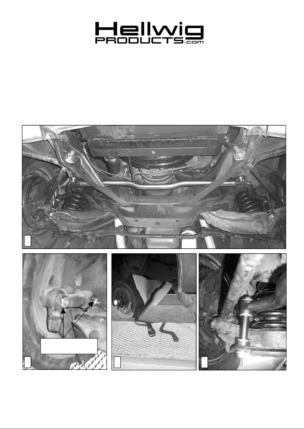
1
Disconnect Passenger
Side Steering Arm Bolts
2 3 4
5713(R-5713) 02/03/06

559-734-7451 800-367-5480 FAX 559-734-7460
TORQUE TABLE
Bolt Size 3/8”— 35 ft lbs * Bolt Size 7/16”— 45 ft lbs* Bolt Size 1/2”—75 ft lbs *Bolt Size 9/16”— 90 ft lbs
SAFETY: BEFOREBEGINNING INSTALLATIONBE SURE TO SET THE PARKINGBRAKE AND
CHOCK THE WHEELS.
NOTE: THIS KIT REQUIRES DISCONNECTING THE STEERING ARM BOLTS. IF YOU
CANNOT PROPERLY PERFORM THIS OPERATION, INCLUDING TORQUING
BOLTS TO FACTORY SPECIFICATION, HAVE A PROFESSIONAL INSTALL YOUR
KIT.
1. Raise the vehicle so that the wheels are off the ground and support the frame using jack stands. Ensure that the vehicle is
secure and stable before working under the vehicle.
2. Turn wheels to the right to ease assembly and disassembly of the sway bar.
3. Disconnect passenger side steering arm bolts as shown in picture (2). Rotate passenger side hub assembly rearward as
shown in photo (3) to allow removal of sway bar
4. Disconnect and remove all mounting hardware from the factory bar.
5. To remove sway bar, slide sway bar to passenger side so that the driver side end can slide through the frame hole. Then
rotate sway bar 180 degrees so that the arms face forward and slide bar through passenger side frame hole.
6. To install the Hellwig sway bar, protect the sway bar finish with a cloth or towel and orient the sway bar with the arms facing forward as shown in photo (3). Slide the driver side end of the sway bar through the passenger side frame hole. Then
rotate sway bar 180 degrees so that the arms face rearward and slide the driver side end of the sway bar through the driver
side frame hole.
7. Reattach steering arm to spindle and torque bolts to factory specification..
8. Lubricate the D-bushings using supplied lubricant and place on sway bar in area shown in photo (1). Install u-plates with
the slotted holes outboard..
9. Align U-plates with holes in frame rail and attach using the 5/16” bolts washers and locknuts provided.
10. Assemble end links to factory control arm brackets as shown in photo (4). Ensure that brake, fuel, and transmission lines
as well as frame mounted componentswill not make contact with the sway bar and its components as the suspension
articulates. The end link spacer can be cut down to provide additional clearance to the frame rail.
11. Tighten all mounting hardware to specified torque.
12. Tighten end links until the bushings bulge slightly.
13. Bounce the vehicle checking for clearance on all under carriage components. Test drive the vehicle and recheck all clearances and the installation alignment. Adjust as needed. Re-check your installation after one week of driving
and periodically on a regular basis.
ATTENTION INSTALLER: BE SURE THAT THE CUSTOMER RECEIVES THIS INSTRUCTION
SHEET, ALL IMORTANT NOTE CARDS AND THE WARRANTY FORM
5713(R-5713) 02/03/06
 Loading...