

559-734-7451 800-367-5480 FAX 559-734-7460
INSTALLATION INSTRUCTIONS
Front Stabilizer Bar 5712
1958-64 Chevrolet Full Size
Thank you for purchasing a quality Hellwig Product.
PLEASE READ THIS INSTRUCTION SHEET COMPLETELY BEFORE STARTING
YOUR INSTALLATION
ATTENTION INSTALLER: BE SURE THAT THE CUSTOMER RECEIVES THIS
INSTRUCTION SHEET, ALL IMORTANT NOTE CARDS AND THE WARRANTY FORM
1
2 3
5712(R-5712) 12/03/06
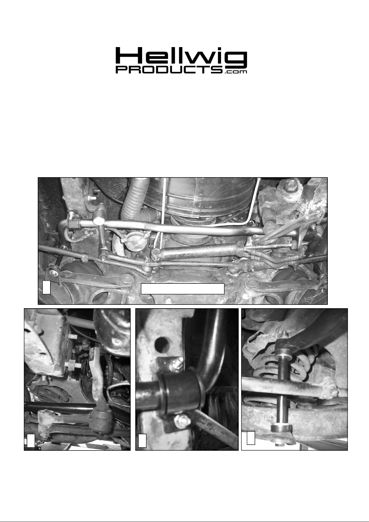
Factory Power Steering Shown
4
559-734-7451 800-367-5480 FAX 559-734-7460
TORQUE TABLE
Bolt Size 5/16”—15 ft lb * 3/8”—35ft lbs * Bolt Size 7/16”— 45 ft lbs* Bolt Size 1/2”—75 ft lbs
SAFETY: BEFORE BEGINNING INSTALLATION BE SURE TO SET
THE PARKING BRAKE AND CHOCK THE WHEELS.
NOTE: THIS KIT REQUIRES DISCONNECTING THE STEERING IDLER ARM
BOLTS. IF YOU CANNOT PROPERLY PERFORM THIS OPERATION, INCLUDING TORQUING BOLTS TO FACTORY SPECIFICATION, HAVE A PROFESSIONAL INSTALL YOUR KIT.
NOTE: THIS KIT MAY REQUIRE DRILLING THE FRAME AND LOWER CONTROL ARMS. INSTALLER MUST ENSURE BAR WILL INSTALL CORRECTLY
BEFORE DRILLING ANY HOLES.
1. Raise the vehicle so that the wheels are off the ground and support the frame using jack stands. Ensure that
the vehicle is secure and stable before working under the vehicle.
2. Turn wheels to the right to ease assembly and disassembly of the sway bar.
3. Disconnect idler arm from frame rail and allow to hang as shown in picture (2). If equipped with factory
power steering, disconnect power steering ram from frame bracket.
4. If vehicle is equipped with a factory installed sway bar, disconnect and remove all mounting hardware from
the factory bar. If not equipped skip to step 6.
5. To remove sway bar, pull the passenger side of the bar forward and over the idler arm bracket that was disconnected in step 4. Then slide sway bar out from between the pitman arm and frame on the driver’s side.
6. To install the Hellwig sway bar, orient the sway bar with the center hump facing down and the arms extending to the rear of the vehicle. Slide the drivers side of the sway bar between pitman arm and frame until end
link attachment hole is over the lower control arm. Then lift the passenger side of the sway bar over the
disconnected idler arm and into position. It may be necessaryto rotate the idler arm out of the wayto allow
installation of the sway bar.
7. Reattach idler arm to frame and torque bolts to factory specification..
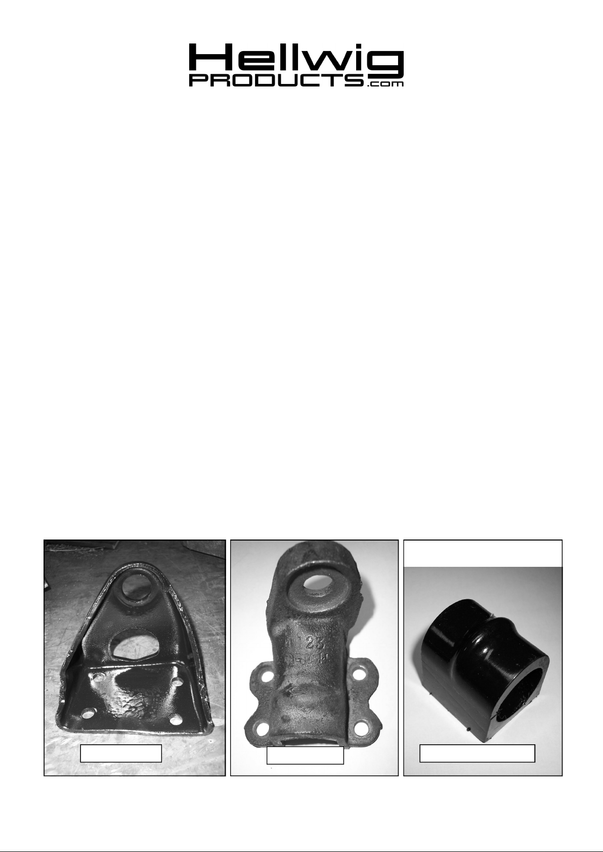
8. Vehicles with factory power steering: There are two power steering ram frame brackets—stamped and
cast. Look at the pictures below to identify your bracket. The cast power steering bracket requires the use
of the special bushing shown. The stamped bracket will use the standard bushings and u-plates supplied in
the kit.
Stamped Bracket
Cast Bracket
Bushing for Cast Bracket
5712(R-5712) 12/03/06

559-734-7451 800-367-5480 FAX 559-734-7460
Cast Bracket—Locate ridge
on bushing in this pocket
65 7
9. Cast Power Steering FrameBracket— Lubricate the special bushing with the raised ridge and place on
sway bar on drivers side. Slide cast power steering frame bracket over bushing aligning ridge on bushing
with pocket in casting as shown in photo (5). Reattach bracket to frame rail using qty (4) 5/16” bolts and
locknuts. Reattach power steering ram per factory instructions. Lubricate standard bushing and place on
sway bar on passenger side. Attach u-plate to frame rail with offset holes to outside of frame rail.
Stamped Power Steering Frame Bracket— Slide bracket over end of drivers side end of sway bar through
hole in bracket as shown in photo (6). Attach bracket to frame using inboard bolt holes only using 5/16”
bolts and locknuts. Lubricate standard bushing and place on sway bar. Attach u-plate with offset holes to
outboard holes in frame and and frame bracket using 5/16” bolts and locknuts. See photo (7). Reattach
power steering ram per factory instructions Lubricate standard bushing and place on sway bar on passenger side. Attach u-plate to frame rail with offset holes to outside of frame rail.
Vehicles without factory power steering—Orient U-plates with offset holes to outside of frame rail and
attach to holes in frame rail using the 5/16” bolts washers and locknuts provided.
10. Ensure that brake, fuel, and transmission lines as well as tie rods and steering components including power
steering ram will not make contact with the sway bar and its components throughout its range of motion.
11. Vehicles without factory installed sway bar: Lower vehicle to the ground so that the full weight of the
vehicle is on the suspension. Then do the following:
a) Install end links and control arm brackets as shown in diagram.
b) Locate sway bar u-plate brackets on frame and control arm for best fit. Make sure that the sway bar
will not contact any frame or steering components as it moves. Ensure that brake, fuel, and transmission lines as well as tie rods and steering components will not make contact with the sway bar
and its components as it moves.
c) When satisfied with the fit, mark holes for control arm brackets on lower control arm. Drill 13/32”
holes in lower control arm to attach control arm brackets. Attach control arm brackets using 3/8” hardware provided.
d) Re-check fit of sway bar and mark holes for u-plate on frame rail. Make sure that the slotted holes in
the u-plates are located outboard as shown in photo (3). When satisfied with fit, drill 11/32” holes in
frame rail to attach bushing u-plates. Attach u-plates using 5/16” hardware provided.
12. Attach end links to control arm brackets as shown in photo (4). If vehicle is to be driven aggressively, it is
recommended that the factory control arm brackets be removed and replaced with the brackets supplied in
this kit (see step 11c and diagram page 4).
13. Tighten all mounting hardware to specified torque.
14. Tighten end links until the bushings bulge slightly.
15. Bounce the vehicle checking for clearance on all under carriage components. Make sure that
the sway bar will not contact any frame or steering components as it moves. Ensure that
brake, fuel, and transmission lines as well as tie rods and steering components will not make
contact with the sway bar and its components as it moves. Test drive the vehicle and recheck all
clearances and the installation alignment. Adjust as needed. Re-check your installation after one week of
driving and periodically on a regular basis.
5712(R-5712) 12/03/06

559-734-7451 800-367-5480 FAX 559-734-7460
ATTENTION INSTALLER: BE SURE THAT THE CUSTOMER RECEIVES THIS IN-
STRUCTION SHEET, ALL IMORTANT NOTE CARDS AND THE WARRANTY FORM
W/O Factory Power Steering
5712(R-5712) 12/03/06
 Loading...