


SFG-830

`
Signal Function Synthesizer
Mode : SFG-830
82FG-83000MC

i
Contents
1. Precautions............................................................................................................1
2. Product Outline......................................................................................................4
3. Features..................................................................................................................5
4. Specifications........................................................................................................6
5. Front and Rear Panels...........................................................................................8
6. Operation..............................................................................................................11
6.1 The Setup of Output Function...................................................................11
6.2 The Setup of Frequency.............................................................................11
6.3 The Setup of Amplitude .............................................................................11
6.4 The Setup of Offset ....................................................................................12
6.5 The Setup of Arbitrary-Wave Compiler.....................................................12
6.6 Deleting the Data of Arbitrary Wave ......................................................... 13
6.7 The Setting of STOR Button......................................................................13
6.8 The Setting of RECL Button ......................................................................14
6.9 The SHIFT Key and Function Keys...........................................................14
6.10 Setup of LIN or LOG Sweep.....................................................................15
6.11 Setup of AM Modulation ..........................................................................16
6.12 Setup of FM Modulation...........................................................................17
6.13 Setup of PM Modulation...........................................................................18
6.14 The Commands of GPIB Serial Interface................................................18
6.15 Syntax and Commands:...........................................................................22
6.16 The Examples of the Communication Interface Software.....................24
7. Adjustment and Correction ................................................................................27
7.1 Preparation .................................................................................................27
7.2 Adjusting Clock..........................................................................................27
7.3 Adjusting the DC of Frequency Double....................................................27
7.4 Adjusting D/A Ref.......................................................................................27
7.5 Adjusting the Bandwidth...........................................................................27
7.6 Adjusting the Filter.....................................................................................28
7.7 Adjusting Harmonic Distortion..................................................................28
7.8 Calibrating by Software .............................................................................28
7.9 Checking Frequency Accuracy.................................................................32
7.10 Checking the Amplitude ..........................................................................32
.8. The Block Diagram and Description of the System.........................................35
Appendix 1 Commands of IEEE488.2………………………………………………..38
Appendix 2 RS-232 Wiring Configuration…………..………………………………43
SFG-830 p.1
EC Declaration of Conformity
We
GOOD WILL INSTRUMENT CO., LTD.
(1) NO. 95 - 11, Pao Chung Rd., Hsin-Tien City, Taipei Hsien, Taiwan
(2) Plot 522, Lorong Perusahaan Baru 3, Prai Industrial Estate, 13600 Prai,
Penang, Malaysia declare, that the below mentioned product
SFG-830
is herewith confirmed to comply with the requirements set out in the Council Directive on the
Approximation of the Law of Member States relating to Electromagnetic Compatibility
(89/336/EEC,92/31/EEC,93/68/EEC) and Low Voltage Equipment Directive(73/23/EEC).
For the evaluation regarding the Electromagnetic Compatibility and Low Voltage Equipment
Directive, the following standards were applied:
EN50081-1: Electromagnetic compatibility -
(1992) Generic emission standard
Part 1: Residential, commercial and light
industry
EN50082-1: Electromagnetic compatibility -
(1992) Generic immunity standard
Part 1: Residential, commercial and light industry
Conducted
Emission
EN 55022 class A Electrostatic Discharge IEC 1000-4-2 (1995)
Radiated Emission (1994) Radiated Immunity IEC 1000-4-3 (1995)
Current Harmonics EN 61000-3-2 +A12 (1996) Electrical Fast
Transients
IEC 1000-4-4 (1995)
Voltage
Fluctuations
EN 61000-3-3 (1995) Surge Immunity IEC 1000-4-5 (1995)
------------------ ---------- ---------- Voltage Dip/Interruption EN 61000-4-11 (1994)
EN50081-2: Electromagnetic compatibility -
(1993) Generic emission standard
Part 2: Industrial Environment
Low Voltage Equipment Directive 73/23/EEC
Conducted Emission EN 55011 class A
Radiated Emission (1991)
Low Voltage Directive
EN
61010-1:(1993)+A2:(1995)
SFG-830 p.1
1. Precautions
SFG-830 is especially designed for safe operation. It has passed rigorous tests of
inclement environment to ensure its reliability and good condition.
The following precautions are recommended to insure your safety and the best
condition of this equipment.
(1) Safety Terms and Symbols
The following terms and symbols may appear in this manual:
!
WARNING
This statement identifies conditions or practices that could
result in injury or loss of life.
!
CAUTION
This statement identifies conditions or practices that could
result in damage to this product or other properties.
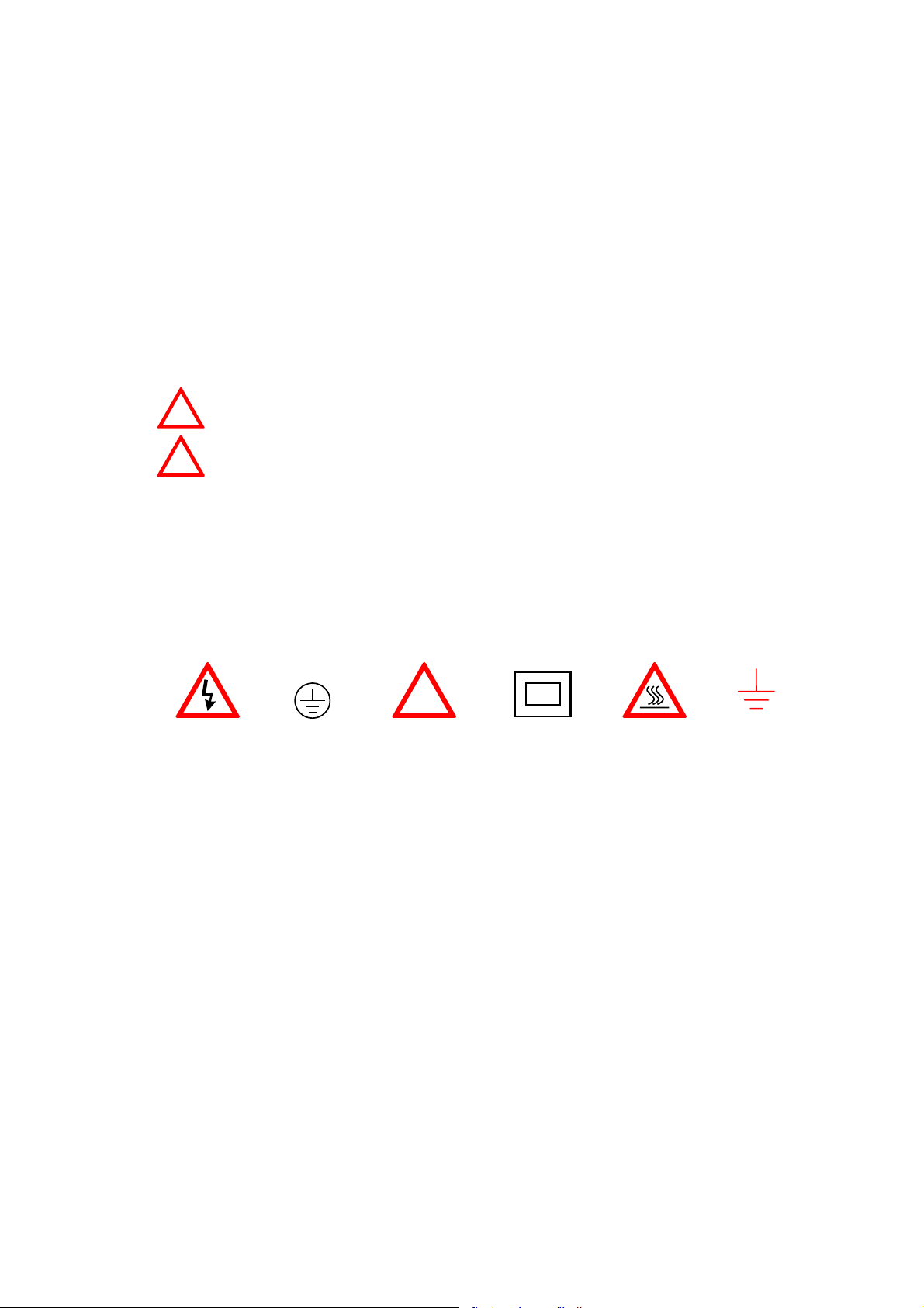
The following terms and symbols may appear on the product:
DANGER
This term indicates an immediately accessible injury hazard.
WARNING
This term indicates that an injury hazard may occur, but is
not immediately accessible.
CAUTION
This term indicates potential damage to this product or other
properties.
!
DANGER
High voltage
Protective
Conductor
Terminal
ATTENTION
refer to manual
Double
Insulated
DANGER
Hot surface
Earth
Ground
Terminal
(2) Do not place any heavy objects on the instrument under any circumstances.
(3) Disassembling the instrument
Due to the precision of this instrument, all the disassembling, adjusting, and
maintenance should be performed by a professional technician. If the instrument
have to be opened or adjusted under some unavoidable conditions, it should be
carried out by a technician who is familiar with SFG-830. Once there is any
abnormality, please contact our company or the agency near you.
(4) Power Supply
AC input should be within the range of line voltage±10%, 50/60Hz. To prevent the
instrument from burning up, be sure to check the line voltage before turning on
power.

p. 2 SFG-830
(5) Grounding
!
WARNING
To avoid electrical shock, the power cord protective grounding
conductor must be connected to ground.
SFG-830 can be operated only with an earth grounded AC power cord that connects
the case and ground well. This is to protect the user and the instrument from the risk
of shock hazard.
(6) Fuse Replacement
!
WARNING
For continued fire protection, replace fuse only with the
specific type and rating. Disconnect the power cord before
replacing fuse.
The fuse blows only if there is anything wrong with the instrument, and SFG-830 will
stop working under this situation. Please check the cause of it, then replace an
proper fuse as listed below. Be sure to use the correct fuse before changing the
applying voltage.
90V ~ 132V : T 0.8A/250V
198V ~ 250V : T 0.5A/250V
F101-102 : T1A/250V
F103-104 : T2A/250V
Check the line voltage setting on the rear panel. If the line voltage setting does not
match the one of your area, change the line voltage setting according to the following
steps:
1. Open the cover of AC socket with flat-blade screwdriver.
2. Remove cam drum, rotate to correct selection and reinsert.
(7) Cleaning the Cabinet
Disconnect the AC power cord before cleaning the instrument.
Use a soft cloth dampened in a solution of mild detergent and water. Do not spray
cleaner directly onto the instrument, since it may leak into the cabinet and cause
damage.
Do not use chemicals containing benzing, benzne, toluene, xylene, acetone, or
similar solvents.
(8) Operation environment
Indoor use
Altitude up to 2000m
Temperature to satisfy the specification : 18
o
C ~ 28
o
C (+64.4
o
F ~ +82.4
o
F)
Operating temperature : 0
o
C ~ 40
o
C (+32
o
F ~ +104
o
F)
Storage temperature : -10
o
C ~ 70
o
C (+14
o
F ~ 158
o
F)
Relative humidity : up to 90% when 0
o
C~35
o
C;
up to 70% when 35
o
C~40
o
C
Installation category: II
Pollution degree: 2
(9) Place SFG-830 in a location of satisfied environment as stated above free from
dust, direct exposition of sunlight, and strong effect of magnetic fields.
SFG-830 p.3
(10) For United Kingdom
NOTE
This lead/appliance must only be
wired by competent persons.
WARNING
THIS APPLIANCE MUST BE
EARTHED
IMPORTANT
The wires in this lead are
coloured in accordance with the
following codes:
Green/Yellow
Blue
Brown
:Earth
:Neutral
:Live
(Phase)
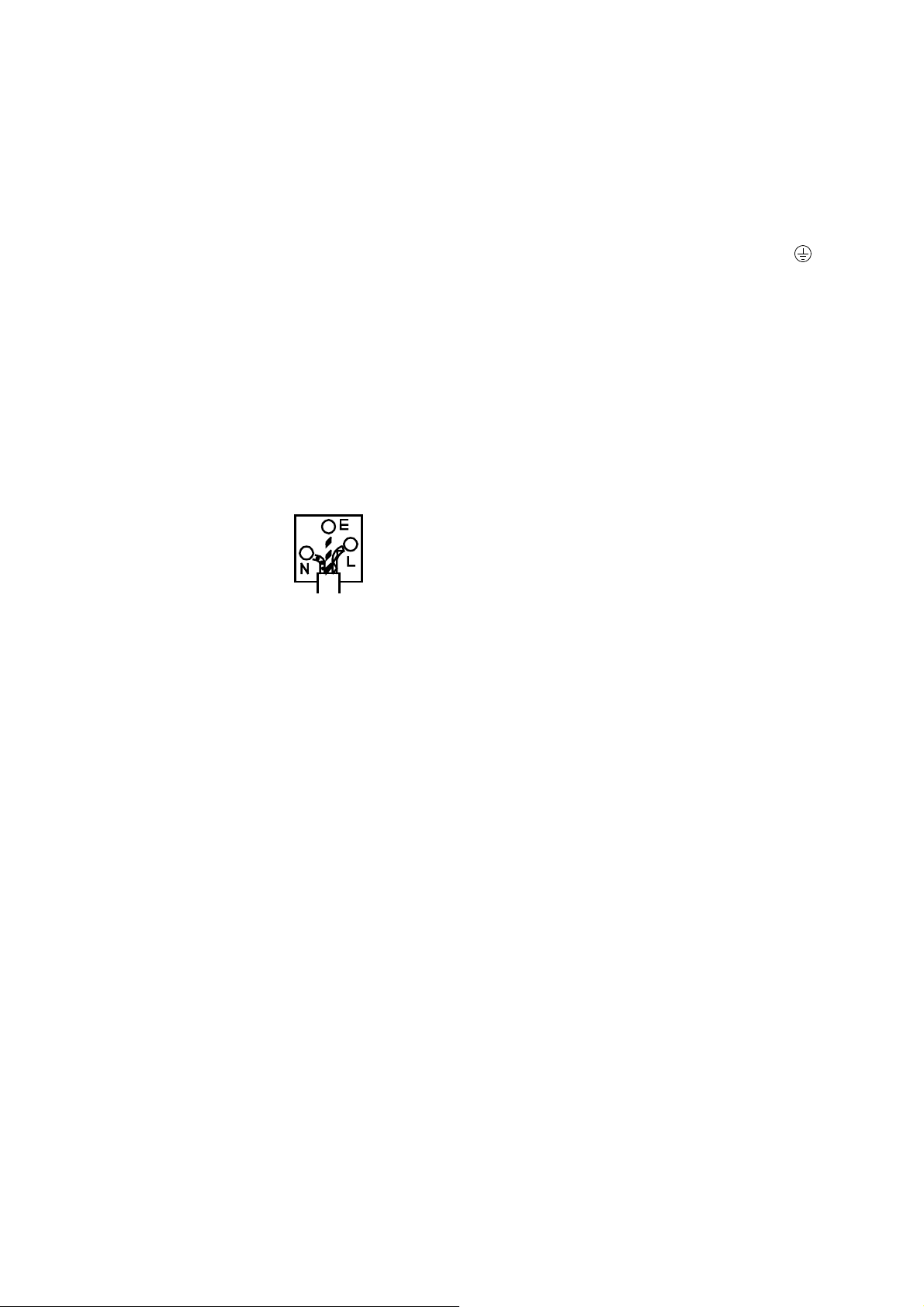
As the colours of the wires in mains leads may not correspond with the
coloured markings identified in your plug/appliance, proceed as follows:
The wire which is coloured Green and Yellow must be connected to the
Earth terminal marked with the letter E or by the earth symbol
or
coloured Green or Green and Yellow.
The wire which is coloured Blue must be connected to the terminal which
is marked with the letter N or coloured Blue or Black.
The wire which is coloured Brown must be connected to the terminal
marked with the letter L or P or coloured Brown or Red.
If in doubt, consult the instructions provided with the equipment or contact
the supplier.
This cable/appliance should be protected by a suitably rated and
approved HBC mains fuse; refer to the rating information on the
equipment and/or user instructions for details. As a guide, cable of
0.75mm
2
should be protected by a 3A or 5A fuse. Larger conductors
would normally require 13A types, depending o n the connection method
used.
Any moulded mains connector that requires removal/replacement must be
destroyed by removal of any fuse and fuse carrier and disposed of
immediately, as a plug with bared wires is hazardous if engaged in a liv e
socket. Any re-wiring must be carried out in accordance with the
information detailed in this section.
p. 4 SFG-830
2. Product Outline
The frequency synthesis method applied by SFG-830 is Direct Digital Synthesis
(DDS), a new technique that generates stable output frequency with extraordinary
resolution.
Unlike SFG-830, traditional frequency synthesized function generators typically use
Phase Locked Loop (PLL) techniques. In order to synthesize frequencies, PLL should
be high-resolution (up to 1:10
6
in general) and needs a stable frequency to be
reference. Due to the utilization of dynamic loop filter, problems such as poor phase
jitter and frequency switching response may occur when running the PLL system.
As in generating waveforms, PLL needs a wave-shaping circuit with an address
counter that controlled by a variable frequency clock. The counter addresses
memory locations in a waveform RAM, and the RAM output is converted by a high
speed digital-to-analog converter (DAC) to produce an analog output signal. Problems
like poor phase jitter and transient response may arise here as well.
Although DDS also generates analogue waveforms by way of the waveform RAM and
high speed DAC, it does not have the problems as PLL does due to the use of fixed
frequency clock (fs). Besides, the resolution of DDS is higher than that of PLL’s.
DDS’s resolution is fs/2
k
where the digit of the control frequency word (K), which is
more than 32bits in general, decides the quality of it.
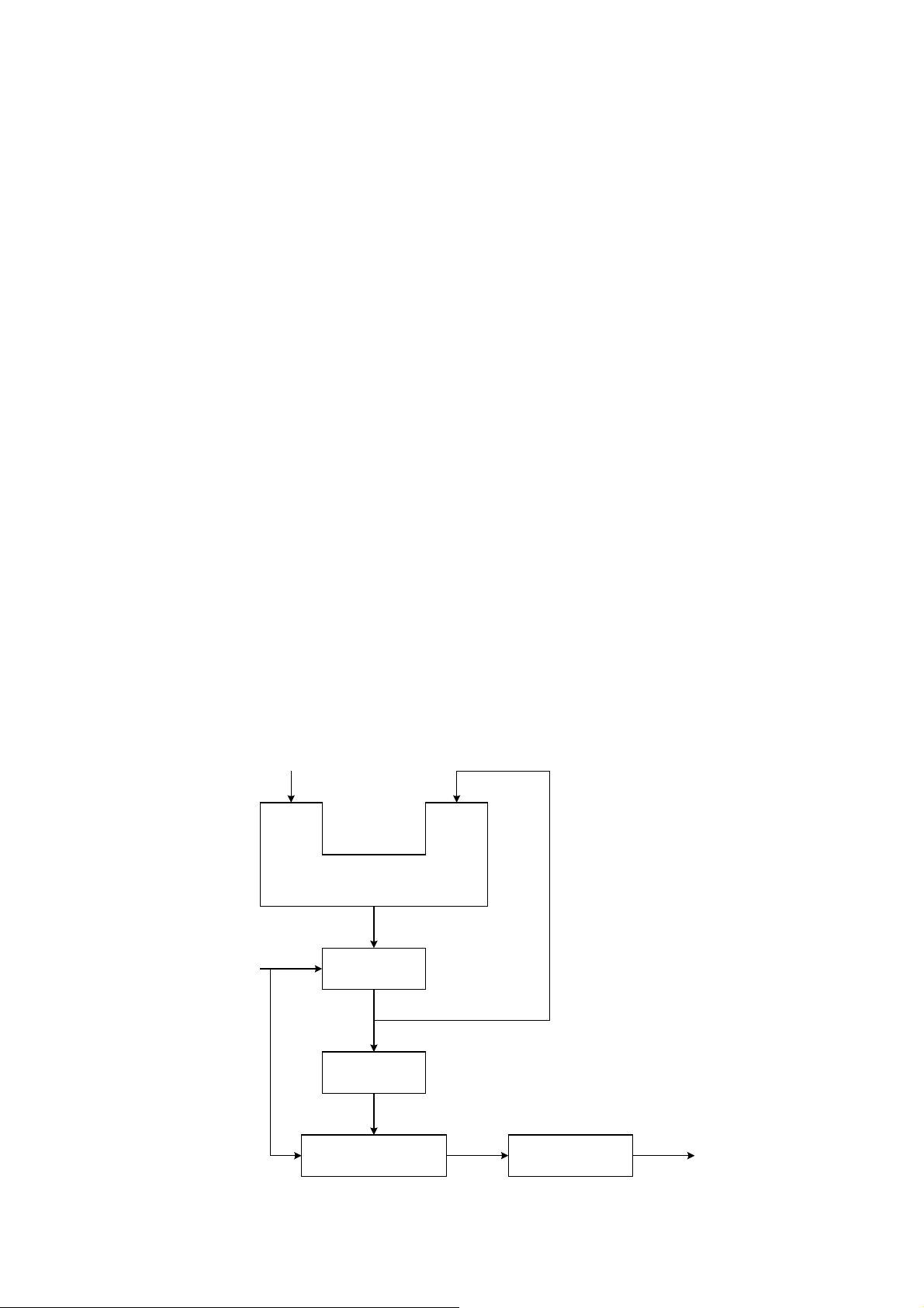
Graph1 indicates the fundamental construction of a DDS frequency synthesizer.
System
Clock
Register
ROM or RAM
Accumulator
Digital / Analog
Converter
Lowpass Filter
32
32
32
24
12
fs
fo
K
(Frequency Control Word)
SFG-830 p.5
A DDS frequency synthesizer consists of a phase accumulator, a lookout table (ROM
or RAM), a Digital-to-Analog Converter (DAC), and a Lowpass Filter (LPF). The
amount in a phase accumulator is controlled by the frequency control word (K), which
will be added by 1 after each system clock cycle(=1/fs). The output of the accumulator
is used to position the data in the Table ROM (or RAM). The digital data will then be
converted into a smooth analog waveform after passing through the DAC and LPF.
3. Features
SFG-830 is a functional signal generator that applies DDS (Direct Digital Synthesis)
technique and can generate frequencies at a resolution of 20mHz, with a high
frequency accuracy of 10ppm. Its main signal source can generate waveforms of sine
wave, square wave, triangle wave, ramp wave, and arbitrary wave.
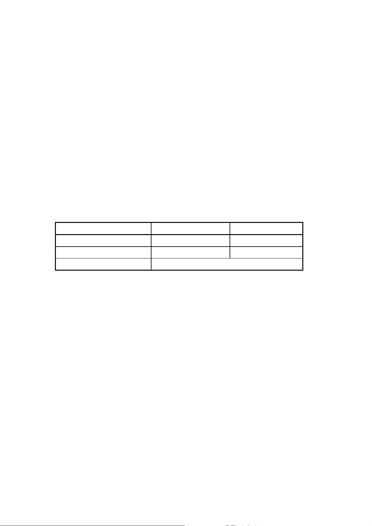
The output frequency range and resolution of each waveform are:
Waveforms Frequency Range Resolution
Sine wave, square wave 20mHz ~ 30MHz 20mHz
Triangle wave, ramp wave 100mHz ~ 100kHz 10mHz
Arbitrary wave 42.949600MHz/N, where N=8,10,12,…,2
15
The depth of AM modulation : 0% ~ 100%
Sweep range : 10mHz ~ 1kHz
With FM and PSK modulation functions, and the users can choose the modulation
signal source among sine wave, square wave, triangle wave, ramp wave, and
arbitrary wave with modulation frequency up to 10kHz.
The digital modulation and sweep functions provide you a stable and high-
resolution (10mHz) modulation environment.
SFG-830 has complete environment of computer interface, including standard
RS232 and optional GPIB, to fulfill your requirement of automatic test and control.
The arbitrary waveform function offers 12000×12bits data length for free compiling.
The user can compile not only with keys on the front panel, but also through a
compiling software “Arbitrary Waveform Composer Software for Windows”
(optional).
p. 6 SFG-830
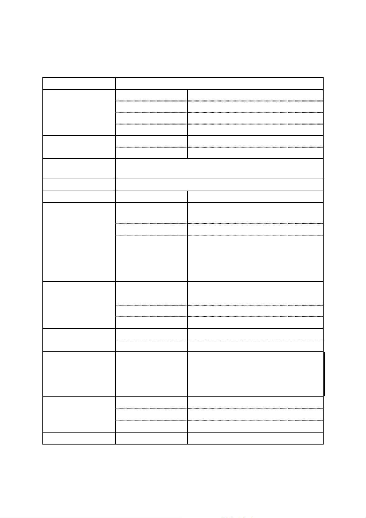
4. Specifications
Output Function
Sine, Triangle, Ramp, Square, Sync Output, Arbitrary
Sine 20mHz ~ 30MHz
Square 20mHz ~ 30MHz
Triangle 100mHz ~ 100kHz
Frequency Range
Ramp 10mHz ~ 100kHz
Sine / Square 20mHz
Frequency
Resolution
Triangle / Ramp 10mHz
Frequency
Accuracy
± 10 ppm
Frequency Aging
± 5 ppm / year
Output Impedance
Source Impedance
50Ω ± 10%
Range
10mV~10Vp-p (into 50Ω) 8 amplitude
ranges | Vac peak | + | Vdc | < 5V
Resolution 3 digits
Amplitude
Accuracy
± 0.5dB +5mV (Sine out)
± 12% +5mV (Square out)
± 5% +5mV (Triangle out)
± 5% +5mV (Arbitrary out)
Range
± 5V (into 50Ω)
| Vac peak | + | Vdc | < 5V
Resolution 3 digits
DC Offset
Accuracy
± 1.5% of setting + 1mV
Sync Output TTL levels
Sync Output
Sync Fan-out > 10 TTL load
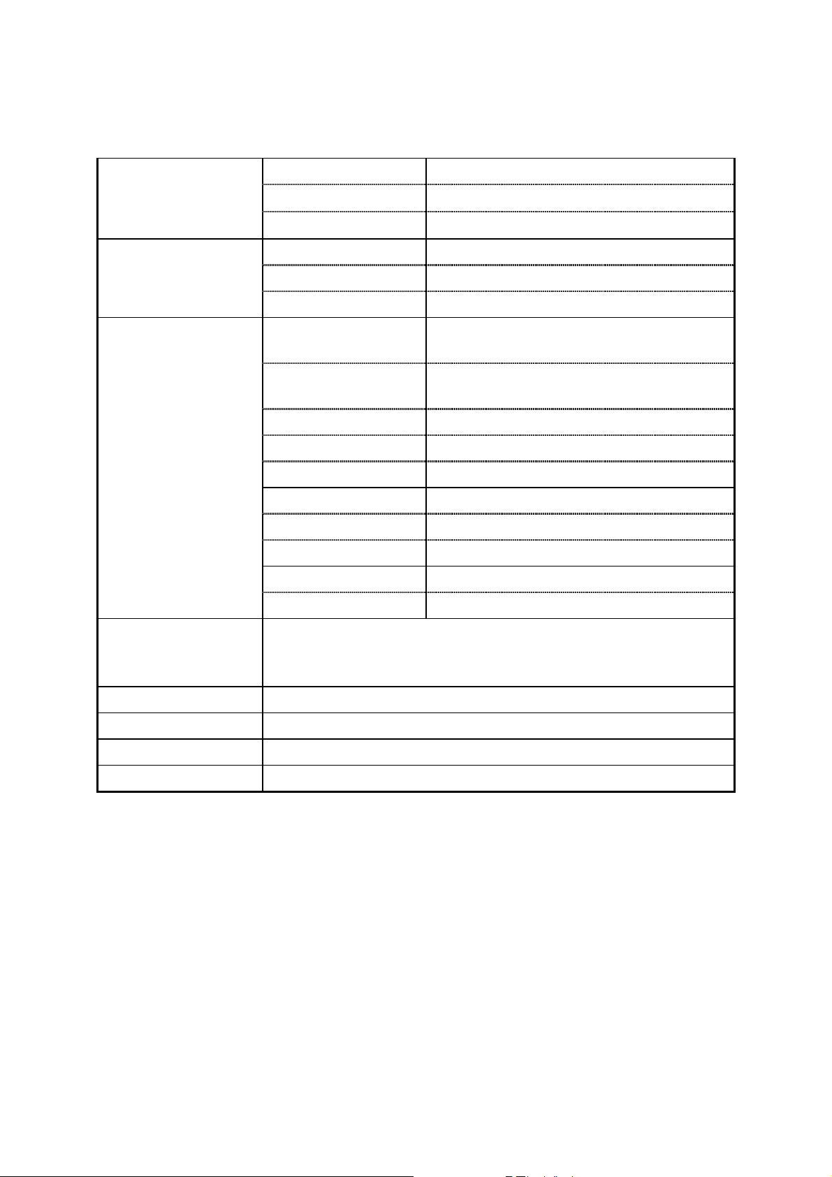
Sine Output
Harmonics
DC
0.1MHz
1MHz
10MHz
~
~
~
~
100kHz
1MHz
10MHz
30MHz
:
:
:
:
-50dBc
-40dBc
-30dBc
-25dBc
Rise / Fall Time
≤ 15ns
Overshoot
≤ 5% (at full scale output)
Square Output
Asymmetry
± 1% of period + 4ns
Triangle and Ramp
Linearity
± 0.1% of full scale output
SFG-830 p.7
Sample Rate 42.949600MHz/N, N=8, 10, 12,…2
15
Waveform Length 12,000 points max.
Arbitrary
Waveforms
Vertical Resolution 12 bits
Sweep Function Line or Log
Sweep Range 20mHz ~ 30MHz
Sweep
Sweep Time 0.01S ~ 1000S
AM Modulation
Function
External, Internal
(sine, triangle, ramp, square)
Modulation Rate
10mHz ~ 10kHz (Internal)
50kHz (max. external)
Modulation Span 0 ~ 100%
Ext. Input
±5V for 100% modulation
Ext. Input Impedance
100 kΩ
FM Function Sine, Triangle, Ramp, Square
Modulation Rate 10mHz ~ 10kHz
Modulation Span 30mHz (100kHz for triangle, ramp)
PSK Span 360 degrees
Modulation
Modulation Rate 20Hz ~ 10kHz
Interface
RS232
GPIB interface (optional)
Arbitrary waveform composer software for Windows(optional)
Accessories
GTL-101 × 1, Instruction Manual × 1
Power Source
100/120/220/ 240V AC ±10%, 50/60Hz
Dimensions
214 (W) × 89 (H) × 370 (D) mm
Weight
Approx. 5kg
p. 8 SFG-830
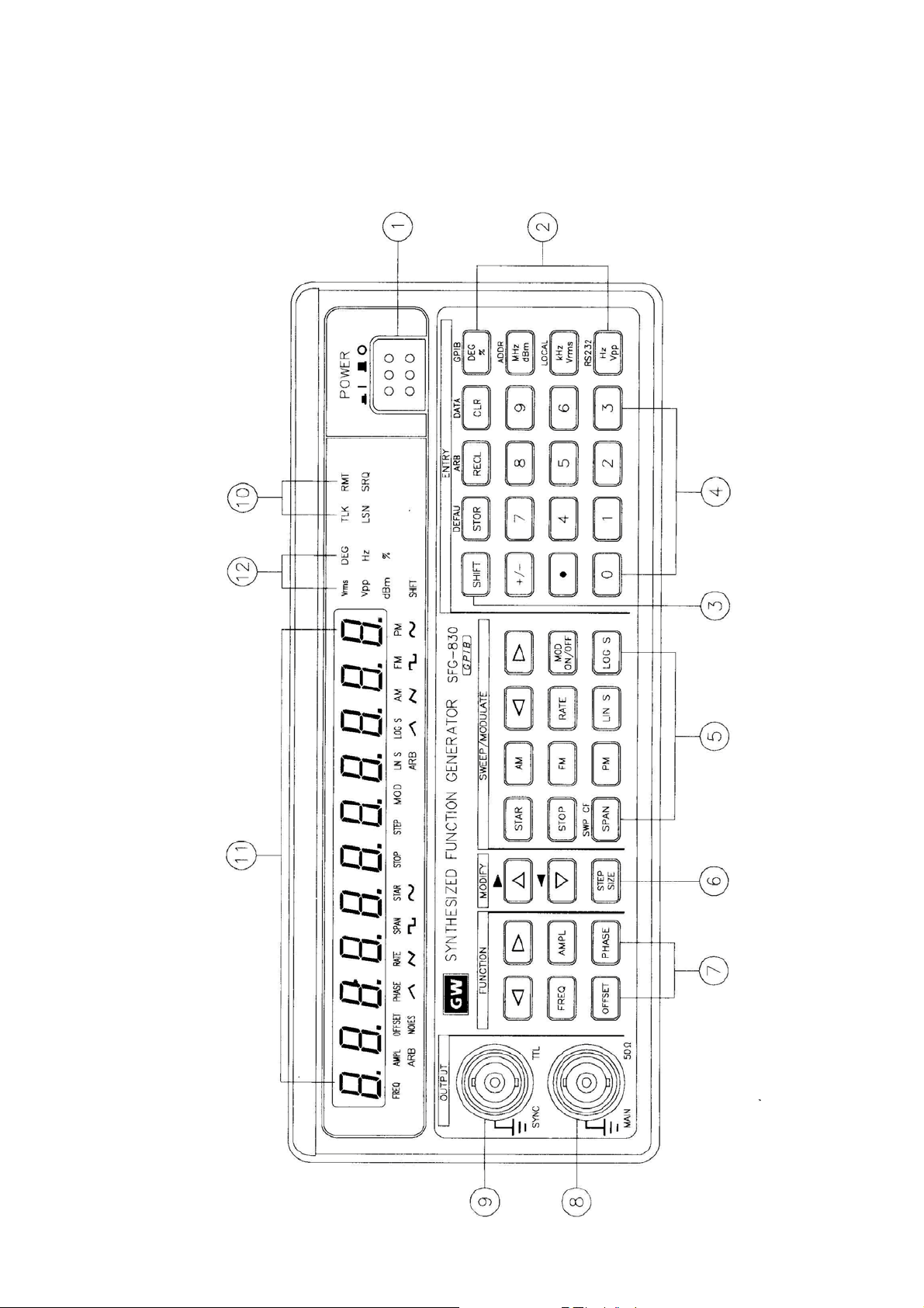
5. Front and Rear Panels
Front Panel

SFG-830 p.9
1
POWER button
:
Push in the button, then the power will be supplied and the
display will light up. The power is off when push the button
again to the flat position.
2
UNIT keys
:
In ‘Normal’ mode, these keys are used to assign the unit and
to set the entered value. For example, you can use dBm,
Vrms, and Vpp to set the output amplitude. They can be used
to set frequency (MHz, kHz, Hz), OFFSET, PHASE, etc.
In STOR or RECL modes, they are used as ‘Enter’.
3
SHIFT key
:
Press this key to set the shift mode, and the SHIFT LED will
light up. For example, press [SHIFT] + [DEFAU] can recall the
default value of this instrument.
4
ENTRY keys
:
[ 0 ] ~ [ 9 ], [ . ], and [ ± ] keys are used to input value. A unit
key should be pressed to set the entered value.
[ CLR ] key is used to delete the entered value entirely and
bring back the previous value.
[ STOR ] key stores the settings into memory.
[ RECL ] key recalls the system settings from memory.
5
SWEEP/
MODULATE keys
:
These keys control the functions of sweep and modulation.
[
] and [ ] keys select the carrier waveform.
[AM], [FM], and [PM] keys set the mode of modulation.
[ LIN ] and [ LOG ] keys set the sweep method.
[ MOD ON/OFF ] initiates sweep or modulation function.
As to the functions of [STAR], [STOP], [SPAN], and [RATE]
keys, please refer to the instruction in Chapter 6.
6
MODIFY keys
:
These keys set the size and the increasing or decreasing
mode of steps.
7
FUNCTION keys
:
These keys controls the output functions.
[
] and [ ] keys select the output signal from arbitrary wave
(ARB), sine wave, triangle wave, etc.
[ FREQ ] key sets the frequency of output.
[ AMPL ] key sets the amplitude of output.
[ OFFSET ] key sets the DC level of output.
[ PHASE ] key sets the phase in PSK modulation mode.
8
MAIN OUTPUT BNC
:
This is the BNC connector that outputs all main signals.
Output resistance is 50Ω.
9
SYNC OUTPUT BNC
:
This is the synchronous output BNC connector that outputs a
TTL-level signal.
10
Interface LEDs
:
These LEDs indicate the current status when operating with
the GPIB interface bus.
11
Parameter display
:
This 11-digit display presents the parameter values and
information about the current status.
12
Unit/Function LEDs
:
These LEDs indicate the unit of the figures on display and the
functions that are currently being used.
p. 10 SFG-830
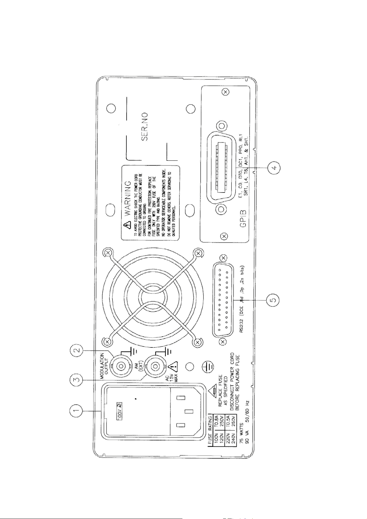
Rear Panel

SFG-830 p.11
1
Power Entry model
:
This is the AC power input terminal. AC input should be within
the range of line voltage±10%, 50/60Hz.
2
Sweep/Modulation
output
:
This terminal outputs the modulated waveform that is
synchronous with the Sweep / Modulation function of this
instrument (±5Vpp Max.)
3
EXT AM Input
:
This is the BNC connector for amplitude modulation input. The
modulation index is 100% when ±5 is input. The input
resistance is 100kΩ.
4
GPIB connector
:
The optional GPIB (IEEE488.2 and SCPI) communication
interface should be plugged here.
5
RS232 connector
:
This is the port of serial RS232 interface. The DCE and Baud
rate is among 300 ~ 19.2k.
6. Operation
6.1 The Setup of Output Function
Use the two buttons [ ] or [ ] in the FUNCTION column on front panel to select
an output waveform. Available waveforms are arranged in sequence SINE,
SQU, TRIG, RAMP, and ARB (from left to right).
6.2 The Setup of Frequency
n Press [ FREQ ] button.
o Key in the desired value of frequency.
p Select a proper unit-button to specify the value.
Example: To set frequency at 250Hz, press [ FREQ ] first; then key in [ 2 ], [ 5 ], [ 0 ], and press
[ Hz ].
The frequency range of waves:
Sine 0.02Hz
∼
30MHz
Square 0.02Hz
∼
30MHz
Triangle 0.1Hz
∼
100kHz
RAMP 0.1Hz
∼
100kHz
ARB 42.949600MHz/N, N=8, 10,12,…2
15
6.3 The Setup of Amplitude
n Press [ AMPL ] button.
o Key in the desired value of amplitude.
p Select a proper unit-button to specify the value.
Example: To set amplitude at 5Vpp, press [ AMPL ] first, then key in [ 5 ] and press [ Vpp ].

p. 12 SFG-830
6.4 The Setup of Offset
n Press [ OFFSET ] button.
o Key in the desired value of offset.
p Select a proper unit-button to specify the value.
Example: To set offset at 1.2Vpp, press [ OFFSET ] first, then key in [ 1 ], [ . ], [ 2 ], and press
[ Vpp ].
The limitations of input : (1) Amplitude should be among 0.01 ~ 10Vpp.
(2) Offset should be among ±5Vpp.
(3) AMPL + 2 × OFFSET ≤ 10Vpp.
6.5 The Setup of Arbitrary-Wave Compiler
This section explains the compiling procedure of arbitrary waveform by using
buttons on the front panel. The detailed example of delivering data through
optional GPIB will be stated in the chapter of communication interface.
n Set the output function to be “ARB” as stated in section 6.1.
o Press [ FREQ ] and the display will show the reading frequency of ARB
function (range 42.9496MHz/N, where N=8, 10, 12,…2
15
).
p Press [ SHIFT ] [ ARB ] to start arbitrary-wave compilation. There will be two
set of figures on the display, the left one indicates the number of a certain point,
and the right one represents the value of that point.
q Use [ ] or [ ] buttons in the MODIFY column to check out the value of the
previous or the next point.
r To edit value of a point, press [ SHIFT ] + [
]; key in numbers, and select a
proper unit-button to specify new value of the point.
Note: [ SHIFT ] and [ ] buttons are used together for switching the blinking state between the
number and the value of a point. Following the order of arranged points to compile
arbitrary-wave is necessary.
Example of Compiling Arbitrary-Wave
The following example will guide you to proceed the compilation of arbitrary-wave.
Here, 8 points (values are identified as 0, 400, 800, 1200, 0, 0, 0, 0 in an order)
will be compiled. The changes of waveform will be observed via an oscilloscope.
Procedure :
n Use [
] or [ ] buttons in FUNCTION column to select [ ARB ] waveform.
o Press [ SHIFT ] and [ ARB ].
ª The display will show “arb edit” for a while then shows “0001 2047”, which
indicates that you are in the compiling mode and the value of the first point is
2047. The number “0001” will be blinking.
 Loading...