


GOS-652G

GOS-6xxG Family
Dual Trace Oscilloscope
Members Of The Family
50MHz Cursor Readout With Delayed Sweep ……… GOS-658G
20MHz Cursor Readout ……….……….……….…… GOS-626G
20MHz Basic with Delayed Sweep GOS-623G
50MHz Basic With Delayed Sweep ……….………… GOS-653G
50MHz Basic ……….……….……….……….……… GOS-652G
35MHz Basic ……….……….……….……….……… GOS-635G
20MHz Basic ……….……….……….……….……… GOS-622G
82OS-658G0MG
⎯ i ⎯
⎯ ii ⎯
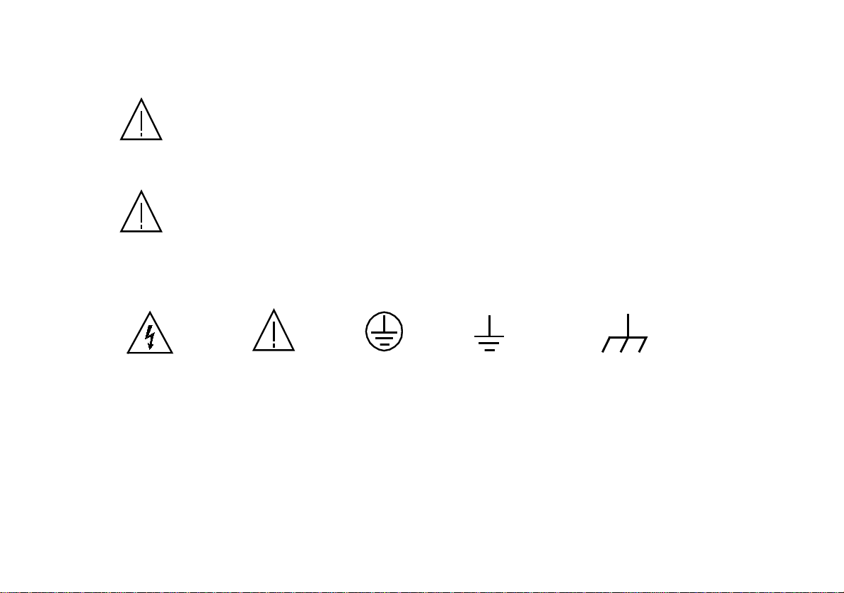
These terms may appear in this manual or on the product:
WARNING. Warning statements identify condition or practices that could result in injury
or loss of life.
CAUTION. Caution statements identify conditions or practices that could result in damage
to this product or other property.
The following symbols may appear in this manual or on the product:
SAFETY TERMS AND SYMBOLS
DANGER ATTENTION Protective Earth(ground) Frame or chassis
High Voltage refer to Manual Conductor Terminal Terminal
Terminal
⎯ iii ⎯
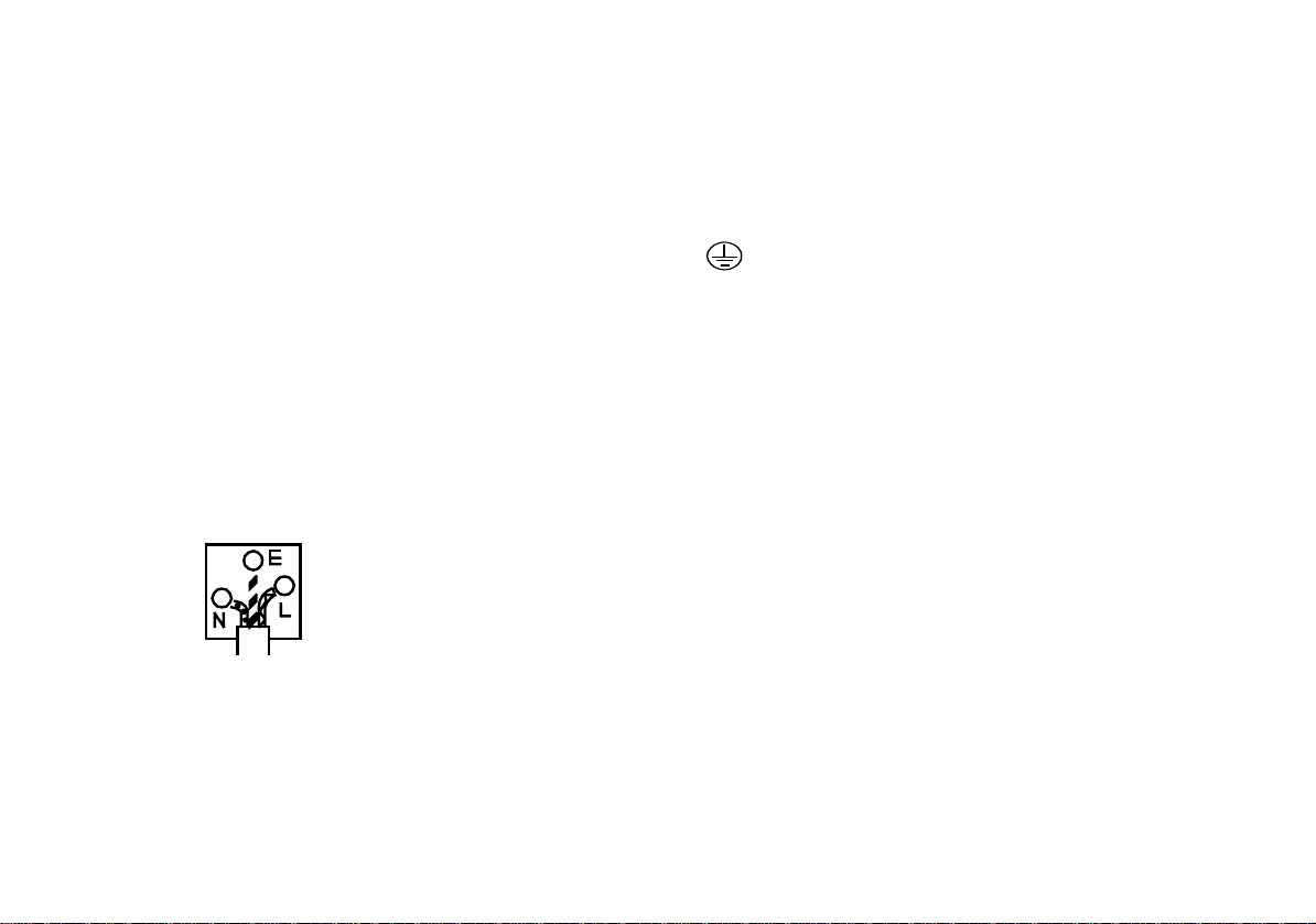
FOR UNITED KINGDOM ONLY
NOTE As the colours of the wires in main leads may not correspond with the colours marking identified in
This lead/appliance must only your plug/appliance, proceed as follows:
be wired by competent persons
WARNING The wire which is coloured Green & Yellow must be connected to the Earth terminal marked with
THIS APPLIANCE MUST BE the letter E or by the earth symbol or coloured Green or Green & Yellow.
EARTHED The wire which is coloured Blue must be connected to the terminal which is marked with the letter
IMPORTANT N or coloured Blue or Black.
The wires in this lead are
coloured in accordance with The wire which is coloured Brown must be connected to the terminal marked with the letter L or
the following code: P or coloured Brown or Red.
Green/ If in doubt, consult the instructions provided with the equipment or contact the supplier.
Yellow: Earth
Blue: Neutral This cable/appliance should be protected by a suitably rated and approved HBC mains fuse : refer
Brown: Live(Phase) to the rating information on the equipment and/or user instructions for details. As a guide, cable
of 0.75mm² should be protected by a 3A or 5A fuse. Larger conductors would normally require
13A types, depending on the connection method used.
Any moulded mains connector that requires removal/replacement must be destroyed by removal
of any fuse & fuse carrier and disposed of immediately, as a plug with bared wires is hazardous if
a engaged in live socket. Any re-wiring must be carried out in accordance with the information
.detailed on this label.
⎯ iv ⎯
EC Declaration of Conformity
We
GOOD WILL INSTRUMENT CO.,LTD.
No. 7-1, Jhongsing Rd, Tucheng City, Taipei County 236. Taiwan.
GOOD WILL INSTRUMENT (SUZHOU) CO., LTD.
No.69 Lushan Road, Suzhou New District Jiangsu, China.
declare that the below mentioned products
GOS-622G,GOS-626G,GOS-623G,GOS-635G,GOS-652G,GOS-653G,GOS-658G
are herewith confirmed to comply with the requirements set out in the Council Directive on the
approximation of the Law of Member States relating to Electromagnetic Compatibility
(89/336/EEC,92/31/EEC,93/68/EEC) and Low Voltage Equipment Directive (73/23/EEC, 93/68/EEC).
For the evaluation regarding the Electromagnetic Compatibility and Low Voltage Equip ment Directive, the
following standards were applied:
EN 61326-1:Electrical equipment for measurement, control and laboratory use––EMC requirements (1997+A1:1998)
Conducted Emission Electrostatic Discharge IEC 1000-4-2 (1995)
Radiated Emission
Current Harmonics EN 61000-3-2 (1995) Electrical Fast Transients IEC 1000-4-4 (1995)
Voltage Fluctuations EN 61000-3-3 (1995) Surge Immunity IEC 1000-4-5 (1995)
------------------ ---------- ---------- Conducted Susceptibility EN 61000-4-6 (1996)
------------------ ---------- ----------
------------------ ---------- ---------- Voltage Dip/Interruption IEC 1000-4-11 (1994)
Low Voltage Equipment Directive 73/23/EEC
Low Voltage Directive
EN 55022 class B (1994)
Radiated Immunity IEC 1000-4-3 (1995)
Power Frequency Magnetic field
EN 61000-4-8 (1993)
IEC/EN61010: 2001
⎯ v ⎯

1. GENERAL
1.1 Description
The 6xxG family oscilloscopes are dual-channel oscilloscopes with maximum sensitivity of 1 mV/DIV, and maximum sweep
time of 10 nSec/DIV. Each of these oscilloscopes employs a 6-inch rectangular type cathode-ray tube with red internal graticule.
623G, 653G and 658G each has a sweep magnification feature with B sweep whereas 626G and 658G provide the read-out function
which enables an easy read out for settings and cursor measured values.
These oscilloscopes are sturdy, easy to operate and exhibit high operational reliability.
1.2 Features
1) High intensity CRT with high acceleration voltage:
The CRT is a high beam transmission, high intensity type with a high acceleration voltage of 2kV for models 622G, 623G,
635G and 626G, and 12kV for models 652G, 653G and 658G. It displays clear readable traces even at high sweep speeds.
2) High stability with less drift:
The oscilloscope employs a temperature compensation circuit which is newly developed to reduce the drift of base lines and DC
balance disturbance caused by the temperature change.
3) A trigger level lock function which makes the triggering adjustment unnecessary:
A new trigger level lock circuit is incorporated. This circuit eliminates the procedures of the troublesome triggering adjustment
not only for displaying signals but also for that of video signals and large duty-cycle signals.
4) TV sync triggering:
The oscilloscopes have a sync separator circuit incorporated within the TIME/DIV switch for automatic triggering of TV-V
and TV-H signals.
5) Linear focus:
Once the beam focus is adjusted to the optimum position, it is automatically maintained regardless to the intensity change.
6) Cursor readout measurement:
The unique easy-to-use cursor and numerical readouts make waveform observations and measurement faster and accurate.
on- screen cursors provide seven functions, including ∆V, ∆V%, ∆VdB, ∆T, 1/∆T, DUTY and PHASE (for 626G, 658G only).
The
⎯ 1 ⎯
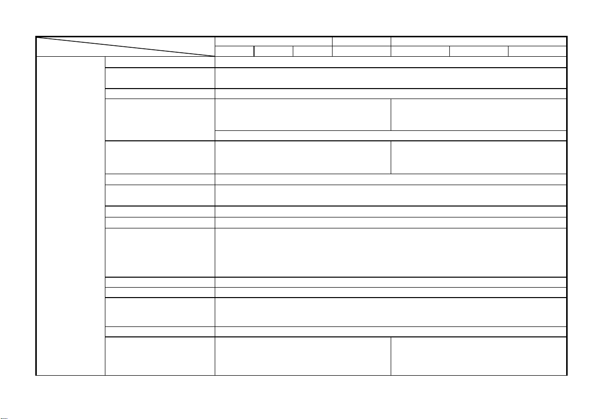
2. TECHNICAL SPECIFICATIONS
SPECIFICATIONS
VERTICAL
AXIS
MODEL
Sensitivity
Sensitivity accuracy
Vernier vertical sensitivity To 1/2.5 or less of panel-indicated value.
Frequency bandwidth (-3dB)
Rise time
Input impedance
Square wave characteristics
DC balance shift
Linearity
Vertical modes CH1 : CH1 single channel.
Chopping repetition frequency Approx. 250kHz
Input coupling AC, DC, GND
Maximum input voltage 400V (DC+AC peak), AC: frequency 1kHz or lower.
Common mode rejection ratio 50:1 or better at 50kHz sinusoidal wave. (When sensitivities of CH1 and CH2 are set equally)
Isolation between channels >1000:1 at 50kHz, >30:1 at 20MHz
20MHz OSCILLOSCOPE 35MHz 50MHz OSCILLOSCOPE
622G 626G 623G 635G 652G 653G 658G
5mV~5V/DIV:DC~20MHz (622G,623G,626G)
5mV~5V/DIV:DC~35MHz (635G)
1mV~2mV/DIV:DC~10MHz
AC coupling: Low limit frequency 10Hz (With reference to 100kHz, 8DIV. Frequency response with - 3dB.)
5mV~5V/DIV:≈ 17.5ns(622G,623G,626G)
5mV~5V/DIV:≈ 10ns(635G)
1mV~2mV/DIV: ≈ 35ns
Overshoot : ≤ 5% (At 10mV/DIV range ) << 5 DIV at the center of display>>
Other distortions and other ranges: 5% added to the above value ( 10℃ to 35℃ (50℉ to 95℉) ).
< ±0.1 DIV of amplitude change when waveform of 2 DIV at graticule center is moved vertically.
CH2 : CH2 single channel.
DUAL
When CHOP switch is pushed in, the two traces are displayed in the CHOP mode at all range.
ADD
When set probe switch at 1:1, the maximum effective readout is 40Vpp (14Vrms at sine wave),
or set probe switch at 1:10, the maximum effective readout is 400Vpp(140Vrms at sine wave).
(622G,623G,626G)
>1000:1 at 50kHz , >30:1 at 35MHz (635G)
(At 5mV/DIV range)
1mV ~ 5V/DIV, 12 steps in 1-2-5 sequence
5mV ~ 5V/DIV: ≤3%, 1mV ~ 2mV/DIV: ≤5% ( 10℃ to 35℃(50℉ to 95℉) )
<< 5 DIV at the center of display>>
5mV~5V/DIV : DC~50MHz,
1mV~2mV/DIV:DC~15MHz
5mV~5V/DIV:≈ 7ns,
1mV~2mV/DIV: ≈ 23ns
1M ohm ±2% // Approx. 25pF
5mV ~5V/DIV: ±0.5DIV, 1mV ~ 2mV/DIV: ±2.0DIV
: CHOP/ALT are auto-set by TIME/DIV switch(CHOP:0.5s~5ms/DIV, ALT:2ms~0.1μs/DIV).
: CH1 + CH2 algebraic addition.
> 1000:1 at 50kHz
> 30:1 at 50MHz
(At 5mV/DIV range)
⎯ 2 ⎯
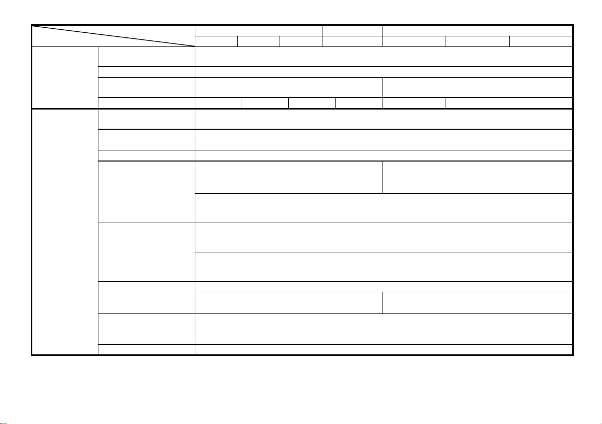
SPECIFICATIONS
VERTICAL
AXIS
TRIGGERING
MODEL
20MHz OSCILLOSCOPE 35MMz 50MHz OSCILLOSCOPE
622G 626G 623G 635G 652G 653G 658G
CH1 signal output
CH2 INV BAL.
Dynamic range
Signal delay
Triggering source
Coupling
Polarity
Sensitivity
>8DIV at 20MHz
>5DIV at 35MHz (635G only)
── ─ ─
CH1, CH2, LINE, EXT ( CH1 and CH2 can be selected only when the vertical mode is DUAL or ADD.
In ALT mode, if the TRIG. ALT switch is pushed in, it can be use for alternate triggering of two different source. )
( TV-V/TV-H can be auto-set by TIME/DIV range. TV-V: 0.5s-0.1ms/DIV; TV-H: 50μs-0.1μs/DIV)
DC~5MHz: 0.5 DIV ( EXT: 0.1V )
5~20MHz
5~35MHz
Approx. 100mV/DIV without termination, 50m V/DIV with 50 ohm termination.
Bandwidth (-3dB) : 622G/623G/626G/635G : 20MHz, 652G/653G/658G : 40MHz
Balanced point variation: ≤ 1 DIV ( Reference at center graticule.)
>8DIV at 50MHz
Leading edge can be monitored.
AC, HF-REJ, TV, DC
+ / −
: 1.5 DIV ( EXT: 0.2V )(622G,623G,626G)
: 1.5 DIV ( EXT: 0.2V)(635G)
DC~10MHz : 0.5 DIV ( EXT: 0.1V )
10~50MHz : 1.5 DIV ( EXT: 0.2V )
TV (video signal): 2.0 DIV ( EXT: 0.2V )
AC coupling: Attenuate signal components of lower than 10Hz.
HF-REJ: Attenuate signal components of higher than 50kHz.
AUTO : Sweeps run in the free mode when no triggering input signal is applied.
(Applicable for repetitive signals of frequency 50Hz or over.)
Triggering modes
NORM : When no triggering signal is applied, the trace is in the READY state and not displayed.
SINGLE : One-shot sweep with triggering signal. Can be reset to the READY state by means of the RESET switch.
The READY lamp (LED) turns on when in the READY state or in the sweep operation
(623G, 626G , 652G , 653G and 658G only)
LEVEL LOCK and ALT Satisfies the value of the above trigger sensitivity plus 0.5 DIV (EXT: 0.05V) for signal of duty cycle 20:80.
triggering
EXT triggering signal input
Input impedance
Max. input voltage
B triggering signal.
Repetition frequency:50Hz~20MHz(622G,623G,626G)
Repetition frequency : 50Hz ~35MHz (635G)
EXT HOR input terminal is used in common.
1M ohm ±2% // approx. 35pF
100V (DC+AC peak), AC: Frequency not higher than 1kHz
The A triggering signal of main sweep is used as the B triggering signal (623G,653G &658G).
Repetition frequency : 50Hz ~ 40MHz
⎯ 3 ⎯
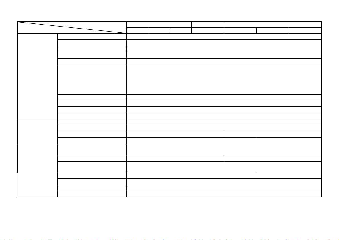
SPECIFICATIONS
HORIZONTAL
AXIS
X-Y MODE
EXT HOR
MODE
Z AXIS
MODEL
20MHz OSCILLOSCOPE 35MHz 50MHz OSCILLOSCOPE
622G 626G 623G 635G 652G 653G 658G
Horizontal axis display A, A INT, B, B TRIG’D (623G, 653G&658G)
A sweep(main sweep ) time
Sweep time accuracy
Vernier sweep time control
Hold off time
B sweep delay system
B sweep(delay sweep) time
Sweep time accuracy
Delay time
Delay jitter
Continuous variable ≧ twice sweep length (time) at 0.1µSec~1mSec/DIV ranges.
Continuous delay and triggered delay
0.1μs~0.5ms/DIV, 12 steps
±3%, (10℃
to 35℃( 50℉ to 95℉ ) ) (623G, 653G&658G)
1μs ~ 5ms
≤ 1/10000
0.1μs ~ 0.5s/DIV, 21 steps in 1-2-5 sequence
±3%, (10℃ to 35℃ ( 50℉ to 95°F ) )
≤ 1/2.5 of panel-indicated value
Sweep magnification 10 times ( maximum sweep time 10ns/DIV )
×10MAG sweep time accuracy 0.1μs~50ms/DIV ±5%, 10ns~50ns/DIV ±8% (10℃ to 35℃(50℉ to 95℉))
Linearity
NORM:±3%, ×10MAG:±5% (±8% for 10ns~50ns/DIV)
Position shift caused by x10MAG Within 2 div. at CRT screen center
Sensitivity Same as vertical axis.(X-axis:CH1 input signal; Y-axis:CH2 input signal.)
Sensitivity accuracy
Frequency bandwidth
X-Y phase difference
Sensitivity
Frequency bandwidth
Phase difference between vertical
axis
Approx. 0.1V/DIV (Trace swept by an external horizontal signal applied to the EXT TRIG
Vertical axis modes are CH1,CH2,DUAL and ADD modes in the CHOP mode.)
NORM:±4%, ×10MAG: ±6% (10℃ to 35℃(50℉ to 95℉))
DC ~ 1MHz (-3dB) DC ~ 2MHz (-3dB)
≤3º at DC ~50kHz ≤3º at DC ~100kHz
DC ~ 1MHz (-3dB) DC ~ 2MHz (-3dB)
≤ 3º at DC ~50kHz ≤ 3º at DC ~100kHz
Sensitivity 3 Vp-p ( Trace becomes brighter with negative input.)
Frequency bandwidth
DC ~5MHz
Input resistance Approx. 5k ohm
Maximum input voltage
50 V ( DC+AC peak, AC frequency≤ 1kHz )
IN terminal.
⎯ 4 ⎯
20MHz OSCILLOSCOPE 35MHz 50MHz OSCILLOSCOPEMODEL
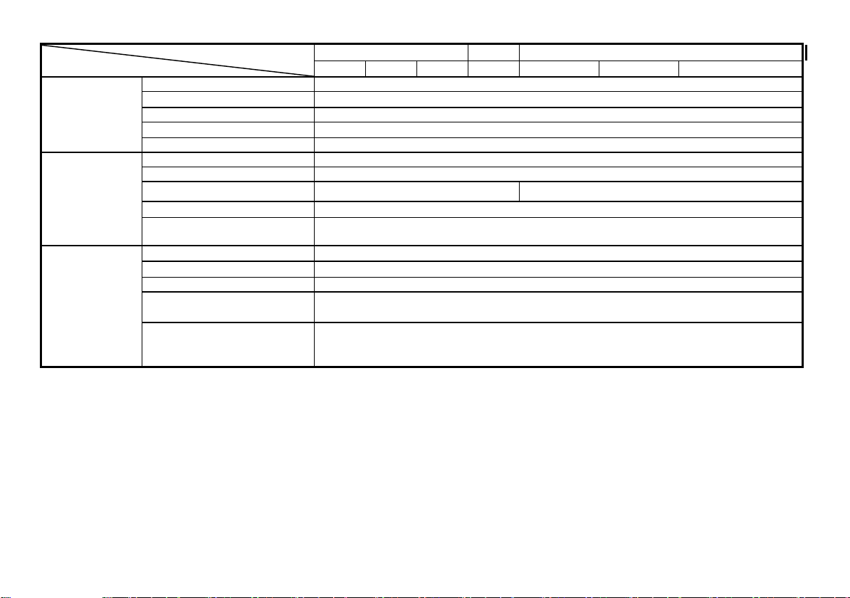
SPECIFICATIONS
CALIBRATION
VOLTAGE
CRT
CURSOR
READOUT
(626G,658G)
Waveform Positive-going square wave
Frequency
Duty ratio Within 48:52
Output voltage
Output impedance Approx. 2 k ohm.
Type 6-inch rectangular type, internal graticule.
Phosphor P 31
Acceleration voltage Approx. 2 kV Approx. 12 kV
Effective screen size
Graticule Internal;
Cursor measurement functions
Cursor display format
Cursor resolution 1/25 DIV
Effective cursor range from center
graticule
Panel setting display
622G
continuous adjustable illumination (623G,626G,652G,653G,658G only)
V/DIV,V-MODE, INV, ALT/CHOP, UNCAL, ADD(SUB), ×10MAG,
PROBE(×1/×10), X-Y, A T/D, TV-V/H,
B T/D(for 658G only)
626G 623G 635G 652G 653G 658G
1 kHz ±5%
2 Vp-p ±2%
8 × 10 DIV ( 1 DIV = 10mm(0.39in))
△V ,△V% ,△VdB, △T ,1/△T ,DUTY ,PHASE
▽(DELTA), ▼(REF)
Vertical: ±3 DIV
Horizontal: ±4 DIV
Measurement category I is for measurements performed on circuits not directly connected to MAINS.
Measurement category II is for measurements performed on circuits directly connected to the low voltage installation.
Measurement category III is for measurements performed in the building installation.
Measurement category IV is for measurements performed at the source of the low-voltage installation.
⎯ 5 ⎯

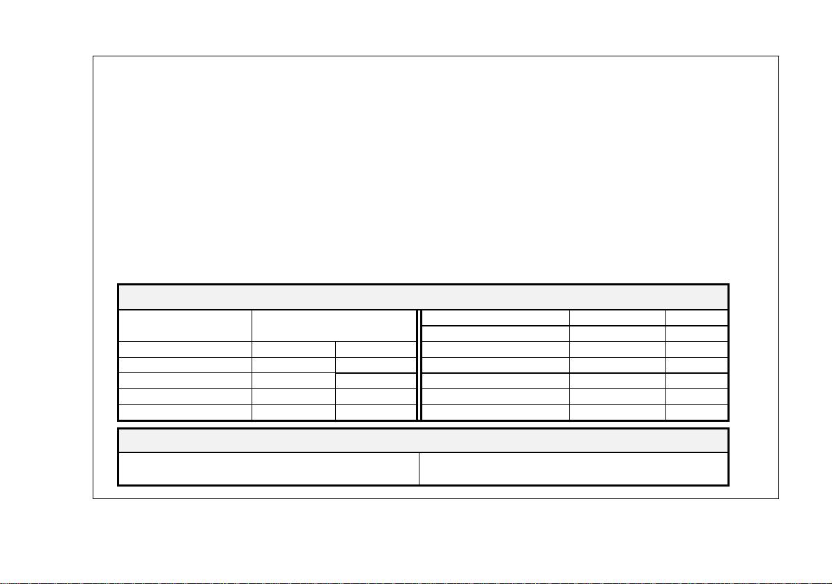
Line Power Requirements Operating Environment Accessories
: AC 100V, 120V, 220V, 230V Indoor use Power cord…...............1Voltage
±10% selectable Altitude up to 2000 m Instruction manual.…..1
Frequency : 50Hz or 60Hz Ambient temperature : Probes......................... 2
Power consumption : Approx. 70VA, 60W(max.) To satisfy specifications : 5° to 35℃ ( 41° to 95° F )
Maximum operating ranges: 0° to 40℃( 32 °to 104° F )
Relative humidity:85% RH(max.) non condensing
Installation Category II
Pollution degree 2
Mechanical Specifications Storage Temperature & Humidity
Dimensions : 310 W x 150 H x 455 D (mm)
Weight : Approx.8.2Kg (18 lbs)
-10° to 70℃,70%RH (maximum)
3. PRECAUTIONS BEFORE OPERATING THE OSCILLOSCOPE
3.1 Unpacking the Oscilloscope
The oscilloscope is shipped from the factory after being fully inspected and tested. Upon receiving the instrument, immediately unpack
and inspect it for any damages that might have been sustained during transportation. If any sign of damage is found, immediately notify the
bearer and/or the dealer.
3.2 Checking the Line Voltage
These oscilloscopes will operate on any one of the line voltage shown in the table below, by inserting the line voltage selector plug in the
corresponding position on the rear panel. Before connecting the power plug to an AC line outlet, make sure the voltage selector is set to the
correct position corresponding to the line voltage. Note the oscilloscope may be damaged if it is connected to the wrong AC line voltage.
WARNING. To avoid electrical shock the power cord protective grounding
conductor must be connected to ground.
⎯ 6 ⎯
 Loading...