


GOM-801H
Declaration of Conformity
We
GOOD WILL INSTRUMENT CO., LTD.
No. 7-1, Jhongsing Rd, Tucheng City, Taipei County 236, Taiwan
GOOD WILL INSTRUMENT (SUZHOU) CO., LTD.
No.69 Lushan Road, Suzhou New District Jiangsu, China.
declares that the below mentioned product
GOM-801H
are herewith confirmed to comply with the requirements set out in the Council Directive on
the Approximation of the Law of Member States relating to Electromagneti c Compatibility
(89/336/EEC, 92/31/EEC, 93/68/EEC) and Low Voltage Equipment Directive
(73/23/EEC, 93/68/EEC).
For the evaluation regarding the Electromagnetic Compatibility and Low Voltage
Equipment Directive, the following standards were applied:
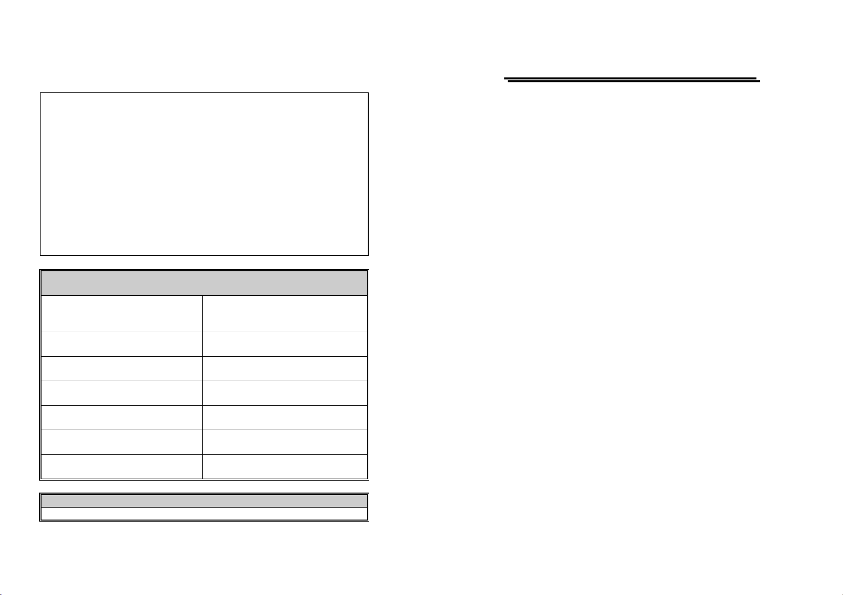
◎ EMC
EN 61326-1: Electrical equipment for measurement, control and laboratory use –– EMC
requirements (1997+A1: 1998 +A2:2001+A3:2003)
Conducted and Radiated Emission
EN 55011: 1998+A1:1999 + A2:2002
Group I class B
Current Harmonic
IEC 61000-3-2: 2000
Voltage Fluctuation
IEC 61000-3-3: 1995+A1:2001
-------------------------
-------------------------
-------------------------
-------------------------
◎ Safety
Low Voltage Equipment Directive 73/23/EEC & amended by 93/68/EEC
IEC / EN 61010-1: 2001
Electrostatic Discharge
IEC 61000-4-2: 2001
Radiated Immunity
IEC 61000-4-3: 2002+A1:2002
Electrical Fast Transients
IEC 61000-4-4: 1995+A1:2001+A2:2001
Surge Immunity
IEC 61000-4-5: 2001
Conducted Susceptibility
IEC 61000-4-6: 2001
Power Frequency Magnetic Field
IEC 61000-4-8: 2001
Voltage Dips/ Interrupts
IEC 61000-4-11: 2004
GOM-801H DC MILLI-OHM METER
USER MANUAL
CONTENTS PAGE
1. PRODUCT IN TR OD UC T ION............................................................1
2. SPECIFI CA TI ON S...............................................................................2
3. PRECAUTI O NS B E FO RE OP ER AT IO N.........................................4
3-1. UNPACKING THE INSTRUMENT..........................................................4
3-2. LINE VOLTAGE..................................................................................4
4. PANEL IN TR OD UCT I O N...................................................................5
5. CIRCUIT D ESCR IPT IO N...................................................................7
6. OPERATION INTRODUCTION .................................................9
6-1. PRELIMINARY OPERATION.................................................................9
6-2. MEASURE MENT OF RESISTOR............................................................9
6-3. MEASURE MENT OF SWITCH.............................................................10
7. MAINTENA NCE.................................................................................11
7-1. LINE FUSE REPLACEMENT................................................................11
7-2. CLEANING ........................................................................................11
i
⎯ ⎯
GOM-801H DC MILLI-OHM METER
USER MANUAL
GOM-801H DC MILLI-OHM METER
USER MANUAL
SAFETY TERMS AND SYMBOLS
These terms may appear in this manual or on the product:
WARNING. Warning statements identify condition or
practices that could result in injury or loss of life.
CAUTION. Caution statements identify conditions or
practices that could result in damage to this product or
other property.
WARNING: This equipment is not for measurements
performed for CAT II, III and IV.
The following symbols may appear in this manual or on the product:
FOR UNITED KINGDOM ONLY
NOTE: This lead/appliance must only be wired by competent persons
WARNING: THIS APPLIANCE MUST BE EARTHED
IMPORTANT: The wires in this lead are colored in accordance with
the following code:
Green/ Yellow: Earth
Blue: Neutral
Brown: Live (Phase)
As the colors of the wires in main leads may not correspond with the
colors marking identified in your plug/appliance, proceed as follows:
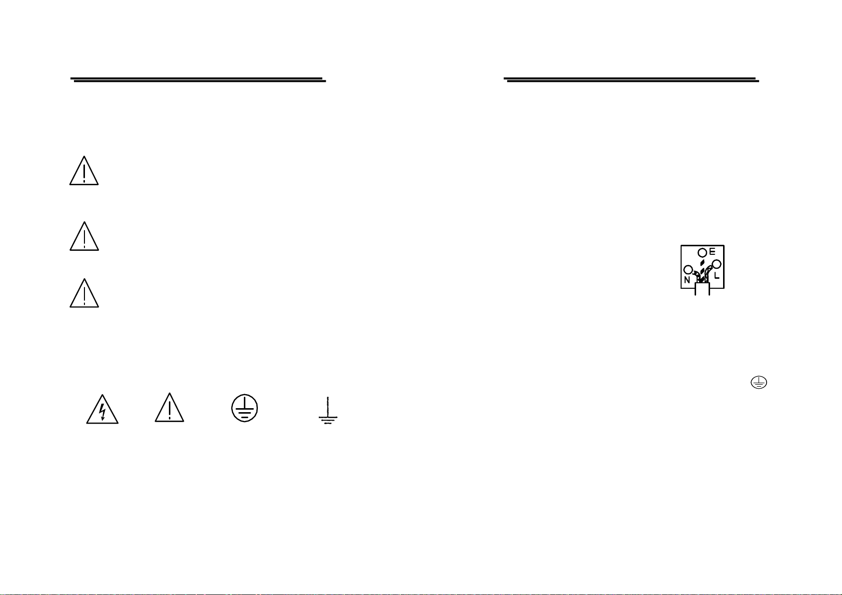
The wire which is colored Green & Yellow must be connected to the
Earth terminal marked with the letter E or by the earth symbol
DANGER ATTENTION Protective Earth(ground)
High Voltage refer to Manual Conductor Terminal
Terminal
ii
⎯ ⎯
or colored Green or Green & Yellow.
The wire which is colored Blue must be connected to the terminal
which is marked with the letter N or colored Blue or Black.
The wire which is colored Brown must be connected to the terminal
marked with the letter L or P or colored Brown or Red.
If in doubt, consult the instructions provided with the equipment or
contact the supplier.
iii
⎯ ⎯

GOM-801H DC MILLI-OHM METER
USER MANUAL
This cable/appliance should be protected by a suitably rated and
approved HBC mains fuse: refer to the rating information on the
equipment and/or user instructions for details. As a guide, cable of
0.75mm
2
should be protected by a 3A or 5A fuse. Larger conductors
would normally require 13A types, depending on the connection
method used.
Any mounded mains connector that requires removal /replacement
must be destroyed by removal of any fuse & fuse carrier and disposed
of immediately, as a plug with bared wires is hazardous if a engaged
in live socket. Any re-wiring must be carried out in accordance with
the information detailed on this label.
GOM-801H DC MILLI-OHM METER
USER MANUAL
1. PRODUCT INTRODUCTION
The Digital Milliohm Meter features with its accuracy and readability. The
circuit of this instrument has equipped with the voltage regulator and
temperature compensation in order for its accuracy not to be influenced by
the unstable AC power source and the alternation of temperature.
The Digital Milliohm Meter is specially produced for the manufacturers of
the low resistor, switch, relay, jacks, plugs, connectors sockets or the electrolytic
capacitor for the QC or IQC purpose, it also can be applied to measure the initial
contact resistance.
iv
⎯ ⎯
1
⎯ ⎯
 Loading...