


Synthesized Function
Generator
SFG-2000/SFG-2100 Series
USER MANUAL
GW INSTEK PART NO. 82FG-21200ME1

ISO-9001 CERTIFIED MANUFACTURER
This manual contains proprietary information, which is protected by copyrights. All rights are reserved. No part of this manual may be photocopied, reproduced or translated to another language without prior written consent of Good Will company.
The information in this manual was correct at the time of printing. However, Good Will continues to improve products and reserves the rights to change specification, equipment, and maintenance procedures at any time without notice.
Good Will Instrument Co., Ltd.
No. 7-1, Jhongsing Rd., Tucheng City, Taipei County 236, Taiwan.

Table of Contents |
|
Table of Contents |
|
SAFETY INSTRUCTIONS .................................... |
2 |
Safety Symbols ...................................... |
2 |
Safety Guidelines ................................... |
2 |
GETTING STARTED .......................................... |
2 |
Technical background............................... |
2 |
Lineup/Features..................................... |
2 |
Front Panel........................................... |
2 |
Rear Panel............................................ |
2 |
Set Up ................................................ |
2 |
Operation Shortcuts ................................ |
2 |
Default Setting Contents ........................... |
2 |
SINE/SQUARE/TRIANGLE WAVE ........................... |
2 |
Select the waveform................................ |
2 |
Set the Frequency................................... |
2 |
Set the Duty Cycle (Square Waveform)........... |
2 |
Set Amplitude........................................ |
2 |
Set Offset ............................................ |
2 |
TTL CMOS OUTPUT ......................................... |
2 |
Select the waveform................................ |
2 |
Set the Frequency................................... |
2 |
Set the Duty Cycle .................................. |
2 |
Set Amplitude........................................ |
2 |
SWEEP ........................................................ |
2 |
AMPLITUDE MODULATION ................................. |
2 |
5

SFG-2000 Series User Manual |
|
FREQUENCY MODULATION ................................. |
2 |
COUNTER INPUT ............................................. |
2 |
STORE/RECALL SETTING.................................... |
2 |
APPLICATION EXAMPLES ................................... |
2 |
Reference Signal for PLL System .................. |
2 |
Trouble-Shooting Signal Source .................... |
2 |
Transistor DC Bias Characteristics Test ........... |
2 |
Amplifier Over-Load Characteristic Test ......... |
2 |
Amplifier Transient Characteristics Test ......... |
2 |
Logic Circuit Test .................................... |
2 |
Impedance Matching Network Test ................ |
2 |
Speaker Driver Test.................................. |
2 |
Sweep for Speaker Test ............................. |
2 |
FAQ ............................................................ |
2 |
APPENDIX ..................................................... |
2 |
Error Messages ....................................... |
2 |
Specification ......................................... |
2 |
Declaration of Conformity.......................... |
2 |
INDEX .......................................................... |
2 |
6
!
SAFETY INSTRUCTIONS
This chapter contains important safety instructions that you must follow when operating SFG-2000 series and when keeping it in storage. Read the following before any operation to insure your safety and to keep the best condition for SFG-2000 series.
Safety Symbols
WARNING
CAUTION
These safety symbols may appear in this manual or on SFG-2000 series.
Warning: Identifies conditions or practices that could result in injury or loss of life.
Caution: Identifies conditions or practices that could result in damage to SFG-2000 series or to other properties.
Attention Refer to the Manual
Earth (ground) Terminal
7
SFG-2000 Series User Manual
Safety Guidelines
General
Guideline
CAUTION
•Do not place any heavy object on SFG-2000 series.
•Avoid severe impacts or rough handling that leads to damaging SFG-2000 series.
•Do not discharge static electricity to SFG-2000 series.
•Use only mating connectors, not bare wires, for the terminals.
•Do not block or obstruct cooling vent opening.
•Do not perform measurements at power source and building installation site (Note below).
•Do not disassemble SFG-2000 series unless you are qualified as service personnel.
(Note) EN 61010-1:2001 specifies the measurement categories and their requirements as follows. SFG-2000 series falls under category II.
•Measurement category IV is for measurement performed at the source of low-voltage installation.
•Measurement category III is for measurement performed in the building installation.
•Measurement category II is for measurement performed on the circuits directly connected to the low voltage installation.
Power Supply |
• |
Input voltage: 115/230V AC +10%, −15%, 50/60Hz |
|
• |
The power supply voltage should not fluctuate more |
WARNING |
|
than 10%. |
|
• |
Connect the protective grounding conductor of the |
|
|
power cord to earth ground, to avoid electrical shock. |
|
|
|
Fuse |
• |
Fuse type: T0.125A/ 250V |
|
• |
Only service personnel are allowed to access internal |
WARNING |
|
fuse holders. |
|
• |
Replace the fuse with the specified type and rating |
|
|
only, for continued fire protection. |
|
• |
Disconnect the power cord before fuse replacement. |
|
• |
Make sure the cause of the fuse blowout is fixed |
|
|
before fuse replacement. |
|
|
|
8

!
Cleaning SFG-2000 series
•Disconnect the power cord before cleaning.
•Use a soft cloth dampened in a solution of mild detergent and water. Do not spray any liquid into SFG-2000 series.
•Do not use chemicals or cleaners containing harsh materials such as benzene, toluene, xylene, and acetone.
Operation |
• |
Location: Indoor, no direct sunlight, dust free, almost |
Environment |
|
non-conductive pollution (Note below) |
|
• |
Relative Humidity: < 80% |
|
• |
Altitude: < 2000m |
|
• |
Temperature: 0°C to 40°C |
(Note) EN 61010-1:2001 specifies the pollution degrees and their requirements as follows. SFG-2000 series falls under degree 2. Pollution refers to “addition of foreign matter, solid, liquid, or gaseous (ionized gases), that may produce a reduction of dielectric strength or surface resistivity”.
•Pollution degree 1: No pollution or only dry, non-conductive pollution occurs. The pollution has no influence.
•Pollution degree 2: Normally only non-conductive pollution occurs. Occasionally, however, a temporary conductivity caused by condensation must be expected.
•Pollution degree 3: Conductive pollution occurs, or dry, non-conductive pollution occurs which becomes conductive due to condensation which is expected. In such conditions, equipment is normally protected against exposure to direct sunlight, precipitation, and full wind pressure, but neither temperature nor humidity is controlled.
Storage |
• |
Location: Indoor |
Environment |
• |
Relative Humidity: < 80% |
|
• |
Temperature: −10°C to 70°C |
|
|
|
9
SFG-2000 Series User Manual
Power cord for the United Kingdom
When using SFG-2000 series in the United Kingdom, make sure the power cord meets the following safety instructions.
NOTE: This lead / appliance must only be wired by competent persons
 WARNING: THIS APPLIANCE MUST BE EARTHED
IMPORTANT: The wires in this lead are coloured in accordance with the following code:
Green/ Yellow: |
Earth |
Blue: |
Neutral |
Brown: |
Live (Phase) |
As the colours of the wires in main leads may not correspond with the colours marking identified in your plug/appliance, proceed as follows:
The wire which is coloured Green & Yellow must be connected to the Earth terminal marked with the letter E or by the earth symbol  or coloured Green or Green & Yellow. The wire which is coloured Blue must be connected to the terminal which is marked with the letter N or coloured Blue or Black.
The wire which is coloured Brown must be connected to the terminal marked with the letter L or P or coloured Brown or Red.
If in doubt, consult the instructions provided with the equipment or contact the supplier. This cable/appliance should be protected by a suitably rated and approved HBC mains fuse: refer to the rating information on the equipment and/or user instructions for details. As a guide, cable of 0.75mm2 should be protected by a 3A or 5A fuse. Larger conductors would normally require 13A types, depending on the connection method used.
Any moulded mains connector that requires removal /replacement must be destroyed by removal of any fuse & fuse carrier and disposed of immediately, as a plug with bared wires is hazardous if a engaged in live socket. Any re-wiring must be carried out in accordance with the information detailed on this label.
10
!
GETTING STARTED
This chapter describes SFG-2000 series in a nutshell, including main features and front/rear/display introduction. Follow the Set Up section to properly install and power up SFG-2000 series.
SFG-2000 |
Technical background............................... |
2 |
series overview |
Series lineup ......................................... |
2 |
|
Main features ........................................ |
2 |
Panel |
Front Panel........................................... |
2 |
introduction |
|
|
|
Rear Panel............................................ |
2 |
Setup |
Tilt stand ............................................. |
2 |
|
Power up ............................................. |
2 |
|
Recall the default setting .......................... |
2 |
|
Functionality check ................................. |
2 |
Quick |
Operation Shortcuts ................................ |
2 |
reference |
|
|
|
Default Setting Contents ........................... |
2 |
11

|
|
SFG-2000 Series User Manual |
||
|
|
|
|
|
|
|
|
|
|
Technical background |
||||
Traditional |
SFG-2000 series uses the latest Direct Digital Synthesis |
|||
function |
(DDS) technology to generate stable, high resolution |
|||
generators |
output frequency. The DDS technology solves several |
|||
problems encountered in traditional function generators, |
||||
|
|
|||
|
|
as follows. |
||
|
|
Constant current circuit methodology |
||
|
|
This analog function generating method uses a constant |
||
|
|
current source circuit built with discrete components |
||
|
|
such as capacitors and resistors. Temperature change |
||
|
|
inside the generator greatly affects the components |
||
|
|
characteristics which lead to output frequency change. |
||
|
|
The results are poor accuracy and stability. |
|
|
DDS |
In DDS, the waveform data is contained in and |
|||
methodology |
generated from a memory. A clock controls the counter |
|||
which points to the data address. The memory output is converted into analog signal by a digital to analog converter (DAC) followed by a low pass filter. The resolution is expressed as fs/2k where fs is the frequency and k is the control word, which contains more than 28bits. Because the frequency generation is referred to clock signal, this achieves much higher frequency stability and resolution than the traditional function generators.
12
!
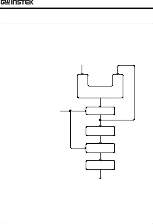
Block diagram |
DDS synthesizer consists of Phase accumulator |
|
(counter), lookout table data (ROM), Digital-to-analog |
|
converter (DAC), and Low-pass filter (LPF). |
Frequency |
|
Control Word (K) |
|
28bit |
28bit |
|
Phase |
|
|
Accumulator |
|
|
28bit |
|
System Clock |
Register |
|
(fs) |
||
|
||
|
Table |
|
|
ROM/RAM |
|
|
12bit |
|
|
Digital-Analog |
|
|
Converter |
|
|
Low-Pass |
|
|
Filter |
|
|
Output (fo) |
The phase accumulator adds the frequency control word K at every clock cycle fs. The accumulator output points to a location in the Table ROM/RAM. The DAC converts the digital data into an analog waveform. The LPF filters out the clock frequency to provide a pure waveform.
13
SFG-2000 Series User Manual
Lineup/Features
Series lineup
Features |
|
|
Duty |
Offset |
TTL/ |
Sweep |
AM/ |
Counter |
Lineup |
|
|
cycle |
|
CMOS |
|
FM |
|
|
|
|
|
|
|
|||
SFG-2004 (4MHz) |
|
|
● |
● |
● |
― |
― |
― |
|
||||||||
SFG-2007 (7MHz) |
|
|
● |
● |
● |
― |
― |
― |
SFG-2010 (10MHz) |
|
|
● |
● |
● |
― |
― |
― |
SFG-2020 (20MHz) |
|
|
● |
● |
● |
― |
― |
― |
SFG-2104 (4MHz) |
|
|
● |
● |
● |
● |
● |
● |
SFG-2107 (7MHz) |
|
|
● |
● |
● |
● |
● |
● |
SFG-2110 (10MHz) |
|
|
● |
● |
● |
● |
● |
● |
SFG-2120 (20MHz) |
|
|
● |
● |
● |
● |
● |
● |
|
|
|
|
|
|
|
|
|
Main features
Performance |
• |
High resolution using DDS and FPGA technology |
|
• |
High frequency accuracy: 20ppm |
|
• |
Low distortion: −55dBc |
|
• |
High resolution 100mHz maintained at full range |
|
|
|
Features |
• |
Wide output frequency range: 4, 7, 10, 20MHz |
|
• |
Various output waveforms: Sine, Square, and Triangle |
|
• |
TTL/CMOS output |
|
• |
Variable DC offset control |
|
• |
Output overload protection |
|
• |
Store/recall: 10 settings |
|
• |
Counter up to 150MHz high frequency (SFG-2100 |
|
|
series) |
|
• |
AM/FM with internal and external (SFG-2100 series) |
|
• |
Sweep mode with LINE and LOG (SFG-2100 series) |
|
|
|
Input/Output |
• |
Frequency output |
Terminals |
• |
TTL/CMOS output |
|
• |
Counter input (SFG-2100 series) |
|
• |
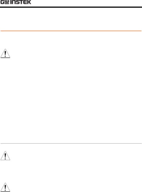
External modulation input (SFG-2100 series) |
|
|
|
14

!
Front Panel
SFG-2100 series front panel
SFG-2000 series front panel
15
|
SFG-2000 Series User Manual |
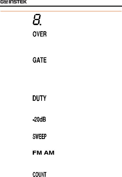
Main display |
Shows the waveform frequency, |
(7 segment) |
counter frequency, and duty cycle. |
For SFG-2100 series only. In the counter mode, indicates that the leftmost digit (100MHz) is hidden but contains a real number. For counter details, see page2.
For SFG-2100 series only. In counter mode, indicates gate selection. For counter details, see page2.
Indicates that the TTL or CMOS output is enabled. For TTL/CMOS details, see page2.
For square waveform only. Indicates that the duty cycle is being edited. For square waveform details, see page2.
Indicates that the waveform output is attenuated by −20dB. For attenuation details, see page2.
For SFG-2100 series only. Indicates that the sweep mode is activated. For sweep details, see page2.
For SFG-2100 series only. Indicates that FM or AM mode is enabled. For modulation details, see page2 (AM) or page2(FM).
For SFG-2100 series only. Indicates that the counter mode is enabled. For counter details, see page2.
For SFG-2100 series only. Indicates that the external modulation input is used. For details, see page2 (AM) or page2(FM).
16
!
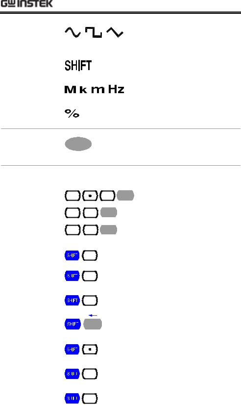
Indicates the waveform shape: Sine,
|
Square, and Triangle. For details, |
|
see page2. |
|
Indicates that the Shift key is |
|
pressed. |
|
Indicates the output frequency: |
|
MHz, kHz, or Hz. |
|
Indicates the duty cycle unit. For |
|
duty cycle details, see page2. |
Waveform |
Selects the waveform shape: sine, |
selection key |
square, and triangle. For details, |
|
see page2. |
Entry keys |
Enters frequency, duty cycle, and various parameters. |
|
1.2MHz |
37kHz
45% (in duty cycle mode) 45Hz (in frequency mode)
Enter duty cycle (page2).
Attenuate the waveform output by −20dB (page2).
Enables TTL/CMOS output (page2).
Deletes previous entry (backspace).
Selects Amplitude Modulation (page2).
Selects Frequency Modulation (page2).
Selects sweep mode (page2).
17
SFG-2000 Series User Manual
|
|
Stores the parameter setting |
|
|
(page2). |
|
|
Recalls the parameter setting |
|
|
(page2). |
|
|
Recalls the default parameter |
|
|
setting (page2). |
|
|
Switches to counter mode |
|
|
(page2). |
|
|
Accepts external modulation |
|
|
signal (page2-AM) or |
|
|
(page2-FM). |
Editing knob |
|
Increases (right turn) or decreases (left |
|
|
turn) the frequency or duty cycle. |
Cursor keys |
|
Moves the editing point left or right in |
|
|
case of manual editing. |
Waveform |
Ω |
Outputs sine, square, and triangle |
output |
|
waveform. BNC terminal, 50Ω output |
|
|
impedance. |
TTL/CMOS output
TTL/CMOS OUTPUT
Outputs TTL or CMOS output waveform, BNC terminal. For TTL/CMOS mode details, see page2.
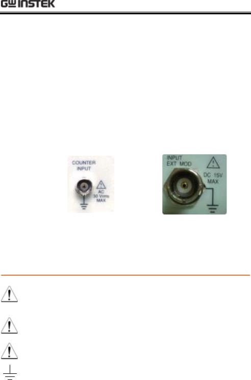
Counter input
Max AC 30Vrms
COUNTER
INPUT
Accepts signals for frequency counting. BNC, AC 30Vrms maximum. For counting mode details, see page2.
18
 Loading...