


GOS-6200
GOS-6200 OSCILLOSCOPE
USER MANUAL
⎯ i ⎯
CONTENTS PAGE
1. PRODUCT INTRODUCTION......................... ........... ........... ..
1-1.Description……………………………………………….
1-2.Feature…………………………………………………....
1
1
2
2. TECHNICAL SPECIFICATIONS………………………… 4
3. PRECAUTIONS BEFORE OPERATION…….…………...
3-1.Unpacking the instrument………………….…………....
3-2.Checking the Line Voltage…………………..…………..
3-3.Environment……………………………………..………
3-4.Equipment Installation and Operati on………………... .
3-5.CRT Intensity……………………………………………
3-6.Withstanding Voltage of Input Terminals …………… ...
8
8
8
9
9
9
9
4. PANEL INTRODUCTION……………………..…………...
4-1.Front Panel……………………………………………….
4-2.Rear Panel……………………………………….……….
10
12
34
5. OPERATION METHOD………………………………...….
5-1.Readout Display……………………………………..…...
5-2.Connecting Input Signals..………………………………
5-3.Adjustment and Checks…………………………………
5-4.Function Check…..………………………………………
5-5.Basic Operation………….….…………………………....
5-6.Measurement Application……………………………….
36
36
38
39
41
43
52
6. MAINTENANCE……………………………………………
6-1.Fuse Replacement………………………………………..
6-2.Line Voltage…………………………………………..….
6-3.Cleaning………………………………………………….
56
56
56
57
7. BLOCK DIAGRAM………………………………………... 58
GOS-6200 OSCILLOSCOPE
USER MANUAL
⎯ ii ⎯
SAFETY TERMS AND SYMBOLS
These terms may appear in this manual or on the product:
WARNING. Warning statements identify condition or
practices that could result in injury or loss of life.
CAUTION. Caution statements identify conditions or
practices that could result in damage to this product or
other property.
The following symbols may appear in this manual or on the product:
DANGER ATTENTION Protective Earth(ground)
High Voltage refer to Manual Conductor Terminal
Terminal
GOS-6200 OSCILLOSCOPE
USER MANUAL
⎯ iii ⎯
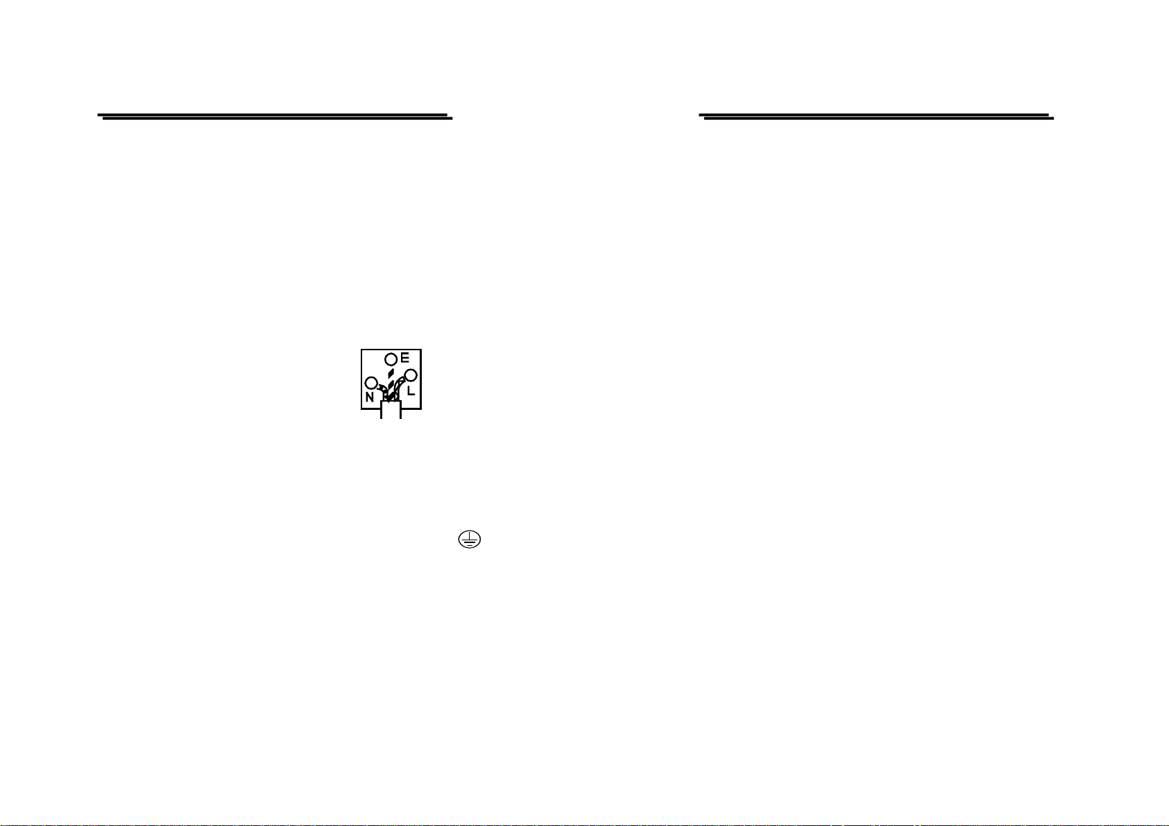
FOR UNITED KINGDOM ONLY
NOTE: This lead/appliance must only be wired by competent persons
WARNING: THIS APPLIANCE MUST BE EARTHED
IMPORTANT: The wires in this lead are coloured in accordance with
the following code:
Green/ Yellow: Earth
Blue: Neutral
Brown: Live (Phase)
As the colours of the wires in main leads may not correspond with the
colours marking identified in your plug/appliance, proceed as follows:
The wire which is coloured Green & Yellow must be connected to the
Earth terminal marked with the letter E or by the earth symbol
or coloured Green or Green & Yellow.
The wire which is coloured Blue must be connected to the terminal
which is marked with the letter N or coloured Blue or Black.
The wire which is coloured Brown must be connected to the terminal
marked with the letter L or P or coloured Brown or Red.
If in doubt, consult the instructions provided with the equipment or
contact the supplier.
GOS-6200 OSCILLOSCOPE
USER MANUAL
⎯ iv ⎯
This cable/appliance should be protected by a suitably rated and
approved HBC mains fuse: refer to the rating information on the
equipment and/or user instructions for details. As a guide, cable of
0.75mm
2
should be protected by a 3A or 5A fuse. Larger conductors
would normally require 13A types, depending on the connection
method used.
Any moulded mains connector that requires removal /replacement
must be destroyed by removal of any fuse & fuse carrier and disposed
of immediately, as a plug with bared wires is hazardous if a engaged
in live socket. Any re-wiring must be carried out in accordance with
the information detailed on this label.
GOS-6200 OSCILLOSCOPE
USER MANUAL
⎯ v ⎯
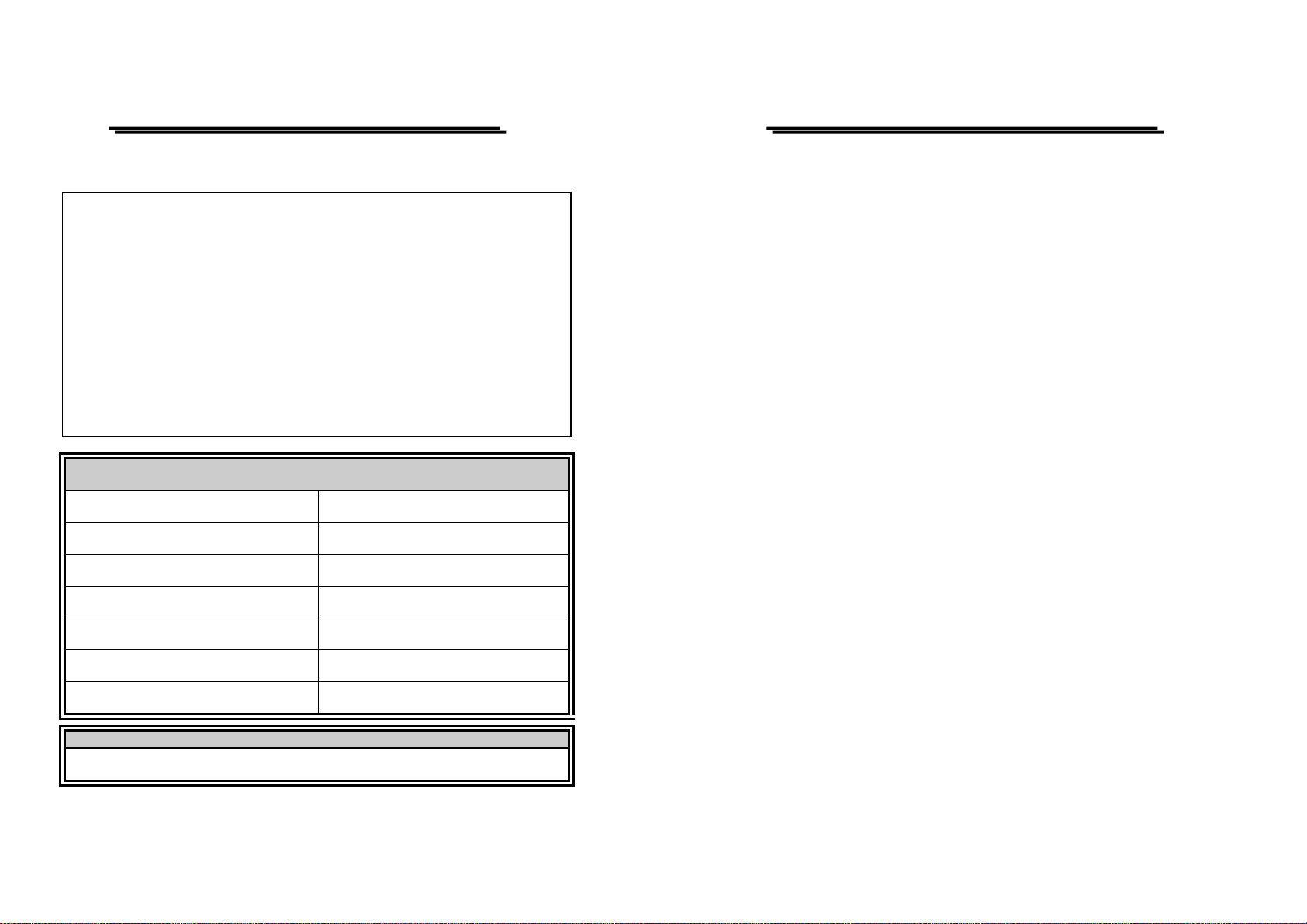
EC Declaration of Conformity
We
GOOD WILL INSTRUMENT CO., LTD.
No. 7-1, Jhongsing Rd., Tucheng City, Taipei County 236, Taiwan
GOOD WILL INSTRUMENT (SUZHOU) CO., LTD.
No.69 Lushan Road, Suzhou New District Jiangsu, C hina.
declares that the below mentioned product
GOS-6200
is herewith confirmed to comply with the requirements set out in the Council Directive
on the Approximation of the Law of Member States relating to Electromagnetic
Compatibility (89/336/EEC, 92/31/EEC, 93/68/EEC) and Low Voltage Equipment
Directive (73/23/EEC, 93/68/EEC).
For the evaluation regarding the Electromagnetic Compatibility and Low Voltage
Equipment Directive, the following standards were applied:
EN 61326-1: Electrical equipment for measurement, control and laboratory use ––
EMC requirements (1997+A1: 1998)
Conducted and Radiated Emissions
EN 55011 class B: 1998
Electrostatic Discharge
EN 61000-4-2: 1995
Current Harmonic
EN 61000-3-2: 1995
Radiated Immunity
EN 61000-4-3: 1996
Voltage Fluctuation
EN 61000-3-3: 1995
Electrical Fast Transients
EN 61000-4-4: 1995
————————————————
Surge Immunity
EN 61000-4-5: 1995
————————————————
Conducted Susceptibility
EN 61000-4-6: 1996
————————————————
Power Frequency Magnetic field
EN 61000-4-8: 1993
————————————————
Voltage Dips/ Interrupts
EN 61000-4-11: 1994
Low Volta
g
e E
q
ui
p
ment Directive 73/23/EEC & amended b
y
93/68/EEC
Safety Requirements
IEC/EN 61010-1: 2001
GOS-6200 OSCILLOSCOPE
USER MANUAL
⎯ 1 ⎯
1.PRODUCT INTRODUCTION
1-1. Description
The GOS-6200 is a 200MHz, two-channel, dual-sweep, portable oscilloscope
for general purpose use. A microprocessor-based operating system controls
most of the functions of the instrument, including cursor readout and
digitized panel setting. On-screen alphanumeric readout and cursor function
for voltage, time, frequency and phase measurement provide extraordinary
operational convenience. It also has the function of TV Line select for
triggering setting, auto measurement for frequency, period, pulse width and
duty cycle and auto setting func tion. Ten different user defined instrument
settings can be saved and recalled without re stricti on.
The vertical deflection system has two input channels. Each channel has 11
basic deflection factors from 2mV to 5V per division. The horizontal
deflection system provides single, dual or delayed sweeps from 0.5s to 20ns
per division (delayed sweep, 50ms to 20ns per division). The trigger system
provides stable triggering over the full bandwidth of the vertical deflection
system.

GOS-6200 OSCILLOSCOPE
USER MANUAL
⎯ 2 ⎯
1-2.Features
Additionally, the oscillo scope off ers seve ral othe r feat ures:
1) High intensity and internal graticule CRT
The oscilloscope employs a high intensity 6-inch retangular type
cathode-ray tube with red internal gratic ule. It displays clear readable
traces even at high sweep speeds. Internal graticule lines eliminate
parallax-viewing erro r be twee n the trac e and the gra ti cul e line .
2) Temperature compensation
The oscilloscope uses a temperature compensation circuit to reduce the
drift of base line and DC balance.
3) 20MHz bandwidth limit
When it is hard to observe or trigger a si gnal because a hi gh-frequency
component is superimposed on the signal, use the 20MHz BWL
function to reduce the bandwidth of the vertical deflection system and
trigger system to 20MHz.
4) Auto-setting
At a press of the AUTOSET button, an optimum time base range is
automatically set to a corresponding change in input signal period. A
signal period from 1.6 to 4 cycles, signal amplitude from 1~7 div
approx. is displayed.
5) TV triggering
Exclusive TV sync separator circuit technology provides stable TV
signal measurements on fields, frames and lines.
6) Z-axis intensity modulation
For applying a blanking signal from an external source. The trace
displayed on the screen may be intensity-modulated where pulse signal
or time-scale marks are required.
GOS-6200 OSCILLOSCOPE
USER MANUAL
⎯ 3 ⎯
7) Trigger signal output
The signal selected by the TRIGGER SOURCE is available. This
output may be used to connect to a frequency counter or other
instrument.
8) Panel setups lock
To avoid unintentional touch of the setting, the feature is extremely
useful for long term and repetitive measurements that used to be
performed under the same test condition of the oscilloscope setting.
9) LED indicator and buzzer alarm
The LED’s located in the front panel assist operation and indicated
additional information. Incorrect operation and the electrical end
position of control knobs are indicated by a warning beep.
10)SMD manufacturing technology
The instrument is built by using the most advanced SMD technology
so as to reduce the number of internal wiring and shorten the foil route
on the pc board. This will also greatly increase the high frequency
performance and the reliability of the product.
11)Auto Measurement
A built-in 6 digits universal counter is accurate within the range of
±0.01% and can measure frequency between 50Hz and 200MHz.
GOS-6200 OSCILLOSCOPE
USER MANUAL
⎯ 4 ⎯
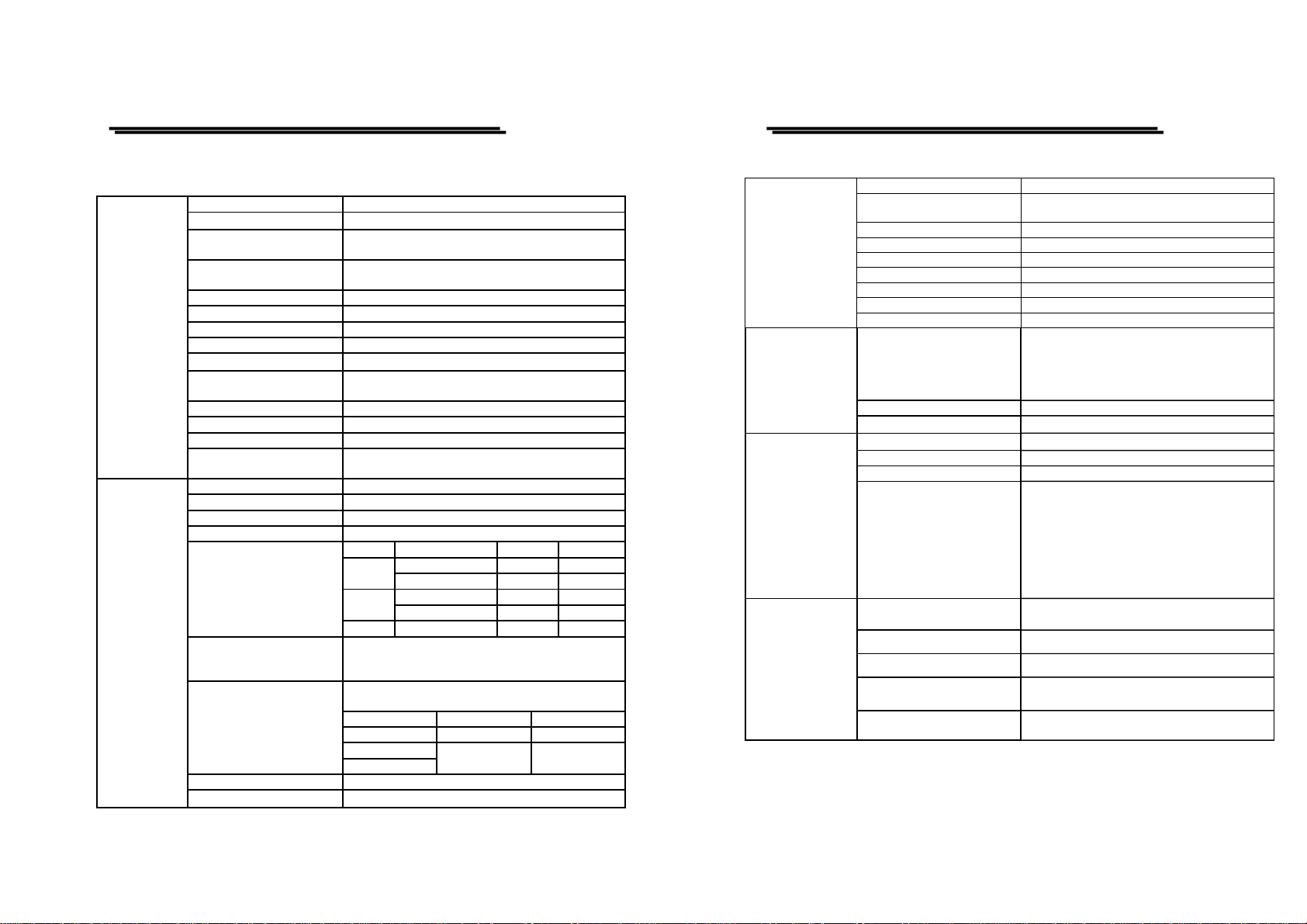
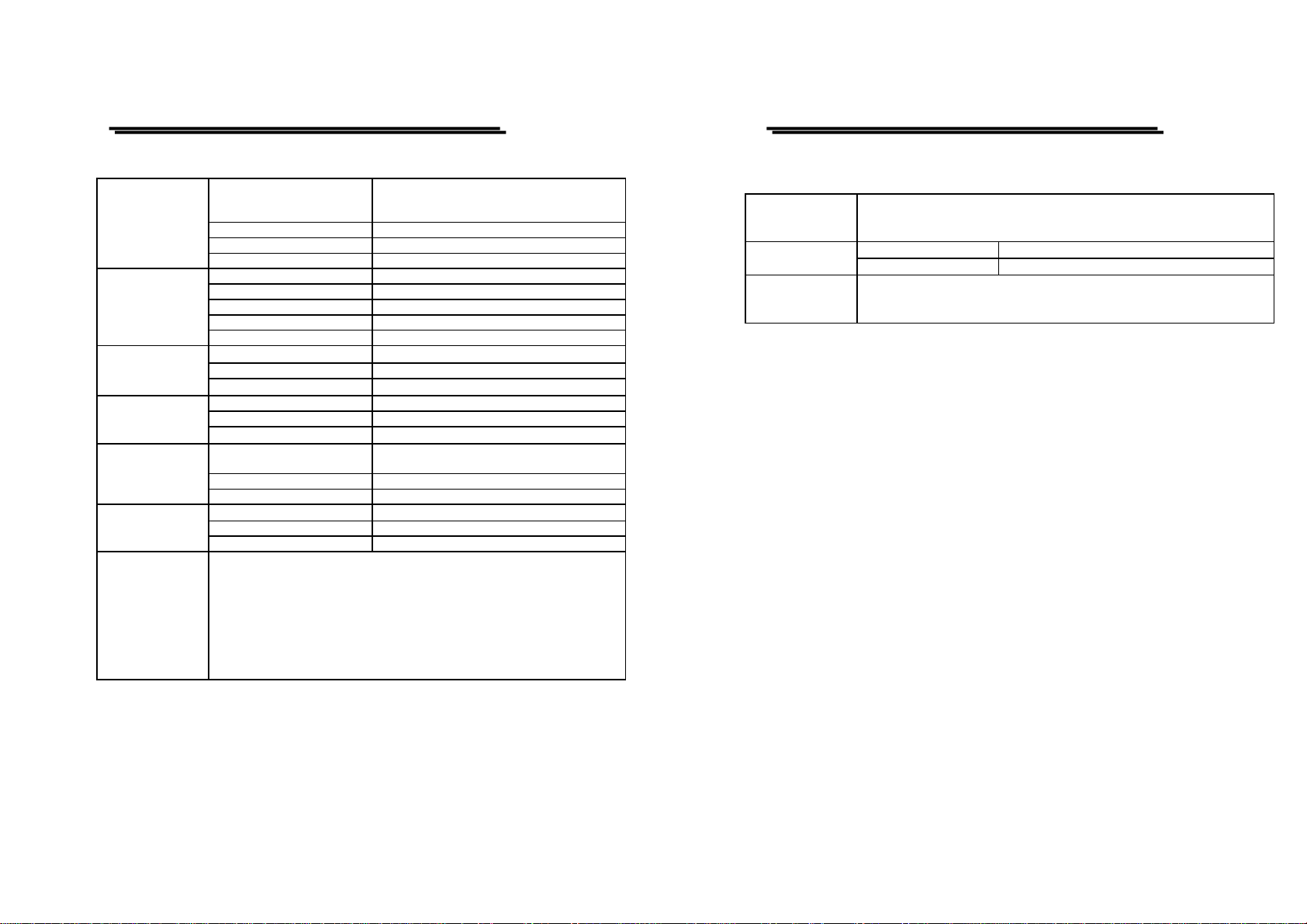
2.TECHNICAL SPECIFICATIONS
Sensitivity 2mV~5V/DIV, 11 steps in 1-2-5 sequence
Sensitivity Accuracy
±3% (5 DIV at the center display )
Vernier Vertical Sensitivity
Continuously variable to 1/2.5 or less than
panel-indicated value
Frequency Bandwidth(-3dB) DC ~ 200MHz (5mV/DIV:DC~150MHz)
(2mV/DIV:DC ~ 20MHz)
Rise Time 1.75ns(5mV/DIV:2.33ns) (2mV/DIV:17.5ns)
Signal Delay Leading edge can be monitored
Maximum Input Voltage 400V (DC+AC) at 1kHz or less
Input Coupling AC, DC, GND
Input Impedance
1MΩ±2% // 25pF approx.
Vertical Modes
CH1,CH2,DUAL(CHOP/ALT),ADD(DIFF mode can
Be established when the CH2 is in the INV mode)
CHOP Repetition Frequency Approx. 250kHz.
Polarity (INV) CH2 only
Bandwidth Limited 20MHz
VERTICAL
DEFLECTION
SYSTEM
Common-mode
Rejection Ration
50:1 or better at 50kHz
Trigger Modes AUTO, NORM, TV
Trigger Source CH1, CH2, LINE, EXT. EXT/10
Trigger Coupling AC, DC, HFR, LFR, NR
Trigger Slope +/- polarity or TV sync polarity
Mode Frequency INT EXT
10Hz~20MHz 0.35DIV 50mVpp
AUTO
20MHz~200MHz 1.5DIV 150mVpp
DC~20MHz 0.35DIV 50mVppNORM
20MHz~200MHz 1.5DIV 150mVpp
Trigger Sensitivity
TV Sync signal 1DIV 200mVpp
Trigger Level Range
INT : ± 4 DIV or more
EXT : ± 0.4 V or more
EXT/10 : ± 4 V or more
TV-V, TV-H, TV-L
TV-Line Selection
Standard Field 1 Field 2
NTSC(525H) 1H~263H 1H~262H
PAL (625H)
TV Sync
SECAM(625H)
1H~313H 1H~312H
Max. External Input Voltage 400V (DC + AC peak) at 1kHz
TRIGGER
SYSTEM
External Input Impedance
1MΩ± 5% // 25pF approx.
GOS-6200 OSCILLOSCOPE
USER MANUAL
⎯ 5 ⎯
Horizontal Modes MAIN(A), ALT, DELAY(B)
A (main) Sweep Time
20ns~0.5sDIV, continuously variable
(UNCAL)
B (delay) Sweep Time 20ns~50msDIV
Accuracy ± 3% (± 5% at × 10 MAG)
Sweep Magnification × 10 (maximum sweep time 2nS/DIV)
Hold Off time Variable
Delay Time 1us~5s
Delay Jitter 1/20000 or less
HORIZONTAL
DEFLECTION
SYSTEM
Alternate Separation Variable
Sensitivity Accuracy
X-axis, Y-axis selectable
X-axis: CH1, CH2Æ 2mV~5V/DIV ± 3%
EXT Æ 0.1V/DIV ± 5%
EXT/10 Æ 1V/DIV ± 5%
Y-axis: CH1,CH2Æ 2mV~5V/DIV ± 3%
X-axis Bandwidth DC~500kHz (-3dB)
X-Y
OPERATION
Phase Error
3°or less at DC~50kHz
Cursor Measurement Function
ΔV,ΔV%,ΔVdB,ΔT,1/ΔT,ΔT%,Δ
Θ
.
Cursor Resolution 1/100 DIV
Effective Cursor Range Vertical: ± 3 DIV; horizontal: ± 4 DIV
CURSOR
READOUT
FUNCTION
Panel setting
Vertical: V/DIV (CH1,CH2),UNCAL, ADD,
INV, P10, AC/DC/GND.
Horizontal: S/DIV (MTB, DTB), UNCAL
x 10MAG, Delay time, Hold-off.
Trigger: Source, Coupling, Slope, Level ,
TV-V/TV-H/TV-L.
Others: X-Y, LOCK, SAVE/RECALL
MEM 0-9.
Parameter Function
FREQ, PERIOD,±WIDTH, ±DUTY,
(+ or – polarity selected by trigger slop.)
Display Digits Max. 6-digits, decimal.
Frequency Range 50Hz~200MHz.
Accuracy
1kHz~200MHz: ±0.01%
50Hz~1kHz : ±0.05%
AUTO
MEASUREMENT
FUNCTION
Measuring Sensitivity
>2div(measuring source selected from CH1
and CH2 as synchronous signal source.)
GOS-6200 OSCILLOSCOPE
USER MANUAL
⎯ 6 ⎯
Type
6-inch rectangular type with internal graticule
0%, 10%, 90% and 100% markers.
8 x 10 DIV (1 DIV = 1 cm)
Phosphor P31
Accelerating Potential 14.5kV approx.
CRT
Illumination Continuous adjustable
External intensity modulation
Coupling DC
Voltage 5V or more
Maximum Input Voltage 30V (DC+AC peak) at 1kHz or less
Z-AXIS
INPUT
Bandwidth DC~5MHz
Voltage
25mV/DIV approx. in 50Ω termination
Frequency Response DC~10MHz
TRIGGER
SIGNAL
OUTPUT
Output Impedance
50Ω approx.
Waveform 1kHz ± 5%, square wave
Voltage 2Vpp ± 2%
CALIBRATOR
OUTPUT
Impedance
2kΩ approx.
Auto Set
Input Channel: CH1,CH2;
Frequency Response 50Hz~50MHz
Panel Setting Save & Recall 10 sets
SPECIAL
FUNCTION
Panel Setups Lock Provided
Voltage
AC 100V, 120V, 230V ± 10% selectable
Frequency 50Hz or 60Hz
LINE POWER
REQUIREMENT
Power Consumption Approx. 90VA, 75W(max.)
OPERATING
ENVIRONMENT
Indoor use
Altitude up to 2000 m
Ambient temperature :
To satisfy specifications : 10° to 35℃ ( 50° to 95°F )
Maximum operating ranges: 0° to 40℃( 32 °to 104°F )
Relative humidity:85% RH(max.) non condensing
Installation Category II
Pollution degree 2
GOS-6200 OSCILLOSCOPE
USER MANUAL
⎯ 7 ⎯
STORAGE
TEMPERATURE
& HUMIDITY
-10° to 70℃, 70%RH(maximum)
Dimensions 310 W × 150 H × 485 D (mm)
MECHANICAL
SPECIFICATION
Weight Approx. 9.5kgs (20.9 lbs)
ACCESSORIES
Power cord….............……….. 1
Instruction manual…………… 1
Probe (×1/×10)…………..… 2
GOS-6200 OSCILLOSCOPE
USER MANUAL
⎯ 8 ⎯
3.PRECAUTIONS BEFORE OPERATION
3-1.Unpacking the Oscilloscope
The product has been fully inspected and tested before shipping from the
factory. Upon receiving the instrument, please unpack and inspect it to
check if there is any damages caused during transportation. If any sign of
damage is found, notify the bearer and/or the dealer immediately.
3-2.Checking the Line Voltage
The oscilloscope can be applied any kind of line voltage shown in the
table below. Before connecting the power plug to an AC line outlet, make
sure the voltage selector of the rear panel is set to the correct position
corresponding to the line voltage. It might be damaged the instrument if
connected to the wrong AC line voltage.
WARNING. To avoid electrical shock the power cord
protective grounding conductor must be connected to ground.
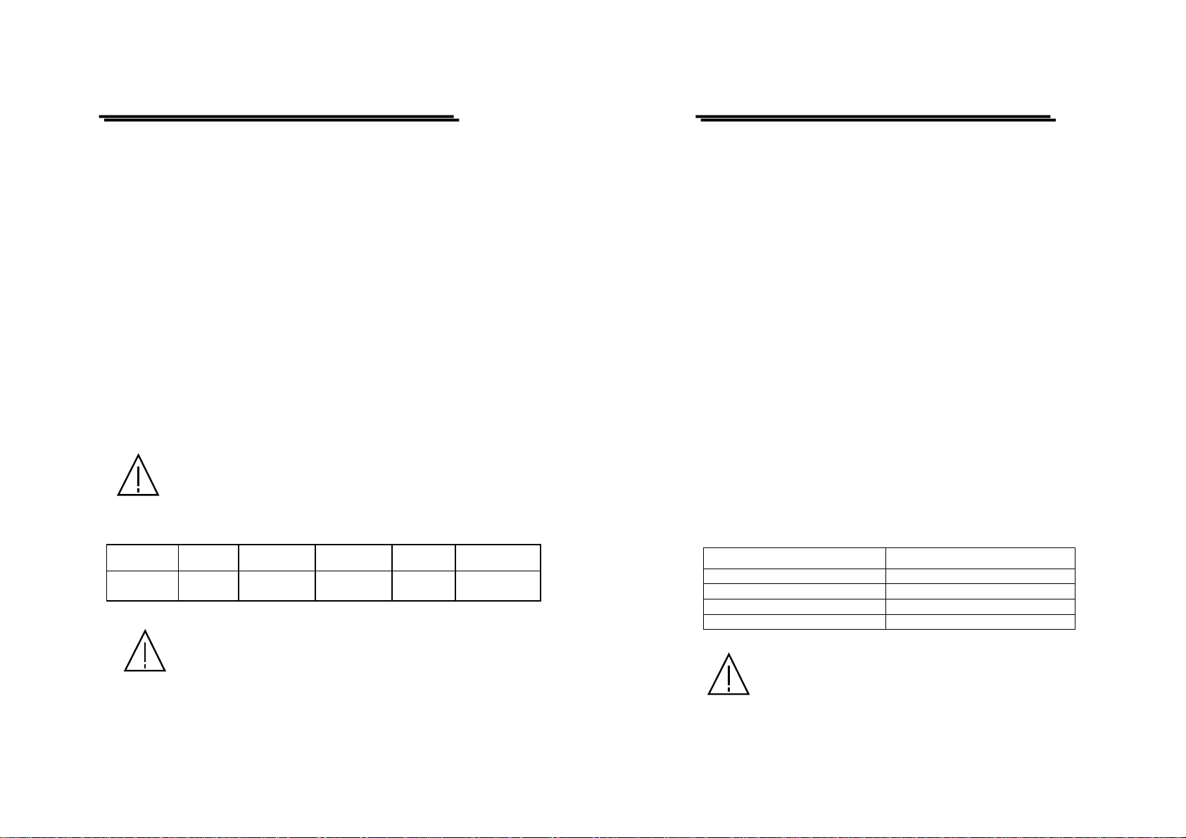
When line voltages are changed, replace the required fuses shown as below:
Line voltage Range Fuse Line voltage Range Fuse
100V
120V
90-110V
108-132V
T 1A250V 230V 207-250V T 0.4A250V
WARNING. To avoid personal injury, disconnect the power
cord before removing the fuse holder.
GOS-6200 OSCILLOSCOPE
USER MANUAL
⎯ 9 ⎯
3-3.Environment
The normal ambient temperature range of this instrument is from 0° to
40°C (32° to 104°F). To operate the instrument over this specific
temperature range may cause damage to the ci rcuit s.
Do not use the instrument in a place where strong magnetic or electric
field exists as it may disturb the measurement.
3-4.Equipment Installation, and Operation
Ensure there is proper ventilation for the vents in the oscilloscope case. If
the equipment is used not according to the specification, the protection
provided by the equipment may be impaired.
3-5.CRT Intensity
To prevent permanent damage to the CRT phosphor, do not make the
CRT trace brighten excessively or leave the spot stay for an unreasonably
long time.
3-6.Withstanding Voltages of Input Terminals
The withstanding voltages of the instrument input terminals and probe
Input terminals are shown in the following table. Do not apply voltages
higher than these limits.
Input terminal Maximum input voltage
CH1, CH2, inputs 400V (DC + AC peak)
EXT TRIG input 400V (DC + AC peak)
Probe inputs 600V (DC + AC peak)
Z AXIS input 30V (DC + AC peak)
CAUTION. To avoid damaging the instrument, do not apply input
voltages of the frequency over 1 kHz to the instrument.
GOS-6200 OSCILLOSCOPE
USER MANUAL
⎯ 10 ⎯
4. PANEL INTRODUCTION
After the instrument is switched on, all the important settings are displayed
in the readout. The LED’s located on the front panel assist operation and
indicate additional information. Incorrect operation and the electrical end
positions of control knobs are indicated by a warning beep.
Except the Power pushbutton (POWER), the Focus control (FOCUS), the
Scale Illumination control (ILLUM) and the Trace Rotation control, all
other controls are electronically selected, an d their functions and settings
can therefore be stored.
The front panel is subdivided into six sections:
z Display controls
z Vertical controls
z Horizontal controls
z Trigger controls
z Measurement and SAVE/RECALL controls
z Input connectors
GOS-6200 OSCILLOSCOPE
USER MANUAL
⎯ 11 ⎯
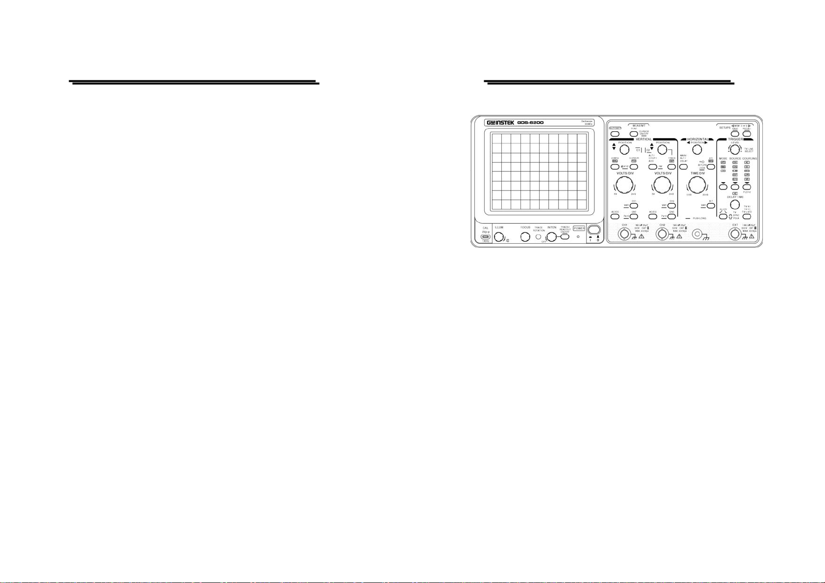
Front panel of GOS-6200
GOS-6200 OSCILLOSCOPE
USER MANUAL
⎯ 12 ⎯
4-1.Front Panel
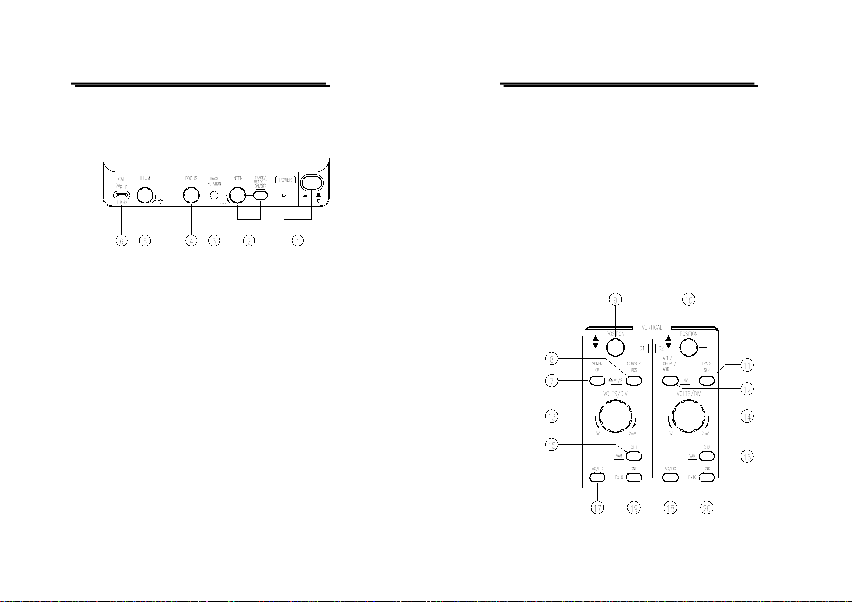
Display controls
The display controls adju st the on-screen appearance of the waveform and
provide a probe compensation signal source.
(1).POWER – Pushbutton and symbols for ON(1) and OFF(0).
When switch on the oscilloscope to have all LEDs lighted and the
software version will be displayed on the sc reen. After the Internal test
is completed successfully, the normal operation mode is present. Then
the last settings become activated and the LED indicates the ON
condition.
(2).INTEN-TRACE/READOUT & READOUT ON/OFF— Control
knob with associated pushbutton and readout display.
The control knob is used for adjusting the traces and readout
intensity. Turning the knob clockwise to increase the intensity and
turning it counterclockwise to decrease the intensity.
The TRACE/READOUT pushbutton is for selecting the intensity
function and indicates the letter “TRACE INTEN” or “READOUT
INTEN” in the readout. Press the pushbutton briefly for the
following sequences:
“TRACE INTEN” — “READOUT INTEN” — “TRACE INTEN”
READOUT ON/OFF
Pressing and holding the TRACE/READOUT pushbutton switches
the readout on or off.
GOS-6200 OSCILLOSCOPE
USER MANUAL
⎯ 13 ⎯
(3).TRACE ROTATION
The TRACE ROTATION is for aligning the horizontal trace in parallel
with graticule lines. This potentiometer can be adjusted with a small
screwdriver.
(4).FOCUS
The control knob effects both the trace and the readout sharply.
(5).ILLUM
The knob controls the graticule illumination brightness.
(6).CAL
The terminal provides a reference signal of 2Vp-p at 1kHz for probe adjustment.
Vertical controls
The vertical contr ols select the displayed signals and contro l t he a mpl it ude
characteristics.

GOS-6200 OSCILLOSCOPE
USER MANUAL
⎯ 14 ⎯
(7).20MHz BWL – Pushbutton with indicator LED.
Briefly pressing the push button, the bandwidth is reduced to approx.
20MHz, and the measurement is made by eliminating undesired high
frequency signal from the waveform. Also the high frequency
component over 20MHz is eliminated from the trigger signal.
(8).CURSOR POS - △V1/2 — Pushbutton with double function and
associated indicator LED.
The function of Cursor Position or CH1/CH2 Position can be selected
only after the pushbutton of Cursor Function is pressed to appear
enabling their cursor measurement. Press the pushbutton once briefly
to have the related LED lighted, the CH1/CH2 POSITION control
knob is then operated as CURSOR 1/CURSOR 2 POSITION control.
△V1/2
The function is required and available only in DUAL mode in
combination with △V (Voltage) measurement. Pressing and holding
the pushbutton, then switch between CH1 and CH2, the measured
result will be displayed by the readout with “△V1…” or “△V2…”
providing the defection coefficient is calibrated. The settings of the
cursors must be related to the signal of the selected channel.
(9).CH1 POSITION – C1 — Control knob with double function.
The vertical trace position of channel 1 can be set with the control knob,
which is also operated as CURSOR 1 position control in cursor
measurement mode.
(10)CH2 POSITION – C2 — Control knob has several functions.
The vertical trace position of channel 2 can be set with the control
knob, which is also operated as CURSOR 2 position control in cursor
measurement mode. In alternate time base mode, this control knob
can be used to separate the DELAY time base trace from the MIAN
time base trace. Please note TRACE SEP (11).
GOS-6200 OSCILLOSCOPE
USER MANUAL
⎯ 15 ⎯
(11)TRACE SEP
The instrument contains a trace separate function which is required in
the alternate time base mode to separate the DELAY time base trace(s)
from the MAIN time base in vertical direction. Consequently this
function is only available in alternate time base mode. Press the
pushbutton once to have the related LED lighted, the CH1 POSITION
control knob is then operated as vertical position control for the trace(s)
of the DELAY time base.
(12)ALT/CHOP/ADD-INV
The pushbutton has several functions, which are required and available
only when both channels are active.
ALT– Displays in the readout, indicates alternate cha nnel switching.
After each time base sweeps the instrument internally , switches over
from channel 1 and channel 2 and vice versa.
CHOP– Indicates chopper mode.
The channel switching occurs constantly between channel 1 and
channel 2 during each sweep.
ADD– Displays in the readout, indicates additional mode.
Whether the algebraic sum (addition) or the difference (subtraction) of
both input signals is displayed, depends on the phase relationship and
the INV setting. As a result, both signals are displayed as one signal.
For correct measurements, the deflection coefficients for both channels
must be equal.
INV—Pressing and holding the pushbutton to set the channel 2 invert
function on or off. The invert on condition is indicated with a horizontal
bar above “CH2” in the readout. The invert function causes the signal
display of channel 2 to be inverted by 180
o
.
 Loading...