

Gold's Gym GGTL046070 Owner's Manual
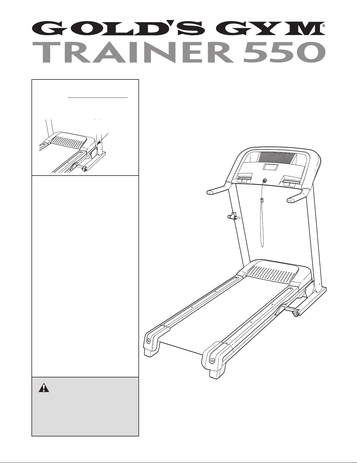
Model No. GGTL04607.0
Serial No.
Write the serial number in the space
above for reference.
Serial Number
Decal
QUESTIONS?
As a manufacturer, we are committed to providing complete customer satisfaction. If you have
questions, or if parts are missing,
PLEASE DO NOT CONTACT THE
STORE; please contact
Customer Care.
USER'S MANUAL
IMPORTANT: You must note the
product model number and
serial number (see the drawing
above) before contacting us:
CUSTOMER HOT LINE:
1-877-776-4777
Mon.–Fri. 6 a.m.–6 p.m. MST
Sat. 8 a.m.–4 p.m. MST
ON THE WEB:
www.goldsgympowerflex.com
CAUTION
Read all precautions and instructions in this manual before using
this equipment. Save this manual
for future reference.
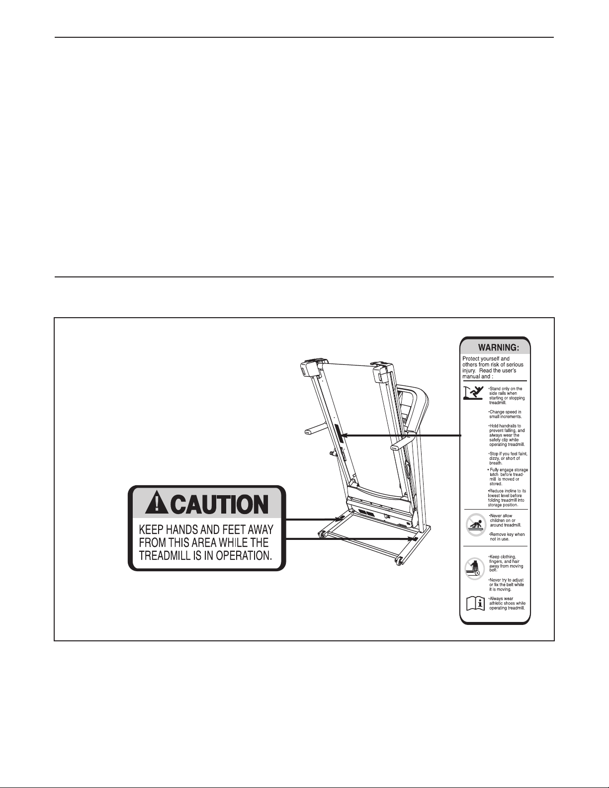
TABLE OF CONTENTS
WARNING DECAL PLACEMENT . . . . . . . . . . . . . . . . . . . . . . . . . . . . . . . . . . . . . . . . . . . . . . . . . . . . . . . . . . . . . .2
IMPORTANT PRECAUTIONS . . . . . . . . . . . . . . . . . . . . . . . . . . . . . . . . . . . . . . . . . . . . . . . . . . . . . . . . . . . . . . . .3
BEFORE YOU BEGIN . . . . . . . . . . . . . . . . . . . . . . . . . . . . . . . . . . . . . . . . . . . . . . . . . . . . . . . . . . . . . . . . . . . . . .5
ASSEMBLY . . . . . . . . . . . . . . . . . . . . . . . . . . . . . . . . . . . . . . . . . . . . . . . . . . . . . . . . . . . . . . . . . . . . . . . . . . . . . . .6
PERATION AND ADJUSTMENT . . . . . . . . . . . . . . . . . . . . . . . . . . . . . . . . . . . . . . . . . . . . . . . . . . . . . . . . . . . .12
O
HOW TO FOLD AND MOVE THE TREADMILL . . . . . . . . . . . . . . . . . . . . . . . . . . . . . . . . . . . . . . . . . . . . . . . . . .21
TROUBLESHOOTING . . . . . . . . . . . . . . . . . . . . . . . . . . . . . . . . . . . . . . . . . . . . . . . . . . . . . . . . . . . . . . . . . . . . .23
EXERCISE GUIDELINES . . . . . . . . . . . . . . . . . . . . . . . . . . . . . . . . . . . . . . . . . . . . . . . . . . . . . . . . . . . . . . . . . . .25
PART LIST . . . . . . . . . . . . . . . . . . . . . . . . . . . . . . . . . . . . . . . . . . . . . . . . . . . . . . . . . . . . . . . . . . . . . . . . . . . . . .27
EXPLODED DRAWING . . . . . . . . . . . . . . . . . . . . . . . . . . . . . . . . . . . . . . . . . . . . . . . . . . . . . . . . . . . . . . . . . . . .28
ORDERING REPLACEMENT PARTS . . . . . . . . . . . . . . . . . . . . . . . . . . . . . . . . . . . . . . . . . . . . . . . . . .Back Cover
LIMITED WARRANTY . . . . . . . . . . . . . . . . . . . . . . . . . . . . . . . . . . . . . . . . . . . . . . . . . . . . . . . . . . . . . .Back Cover
WARNING DECAL PLACEMENT
The decals shown here have been applied in
the locations shown. If a decal is missing or
illegible, call the telephone number on the
front cover of this manual and request a
free replacement decal. Apply the decal in
the location shown. Note: The decals may not
be shown at actual size.
GOLD'S GYM is a registered trademark of Gold's Gym International, Inc. This product is manufactured and
distributed under license from Gold's Gym Merchandising, Inc.
2

IMPORTANT PRECAUTIONS
WARNING: To reduce the risk of serious injury, read all important precautions and in-
structions in this manual and all warnings on your treadmill before using your treadmill. ICON assumes no responsibility for personal injury or property damage sustained by or through the use of
his product.
t
1. Before beginning any exercise program, consult your physician. This is especially important for persons over the age of 35 or persons with pre-existing health problems.
2. It is the responsibility of the owner to ensure
that all users of this treadmill are adequately
informed of all warnings and precautions.
3. Use the treadmill only as described.
4. Place the treadmill on a level surface, with at
least 8 ft. (2.4 m) of clearance behind it and 2
ft. (0.6 m) on each side. Do not place the
treadmill on any surface that blocks air openings. To protect the floor or carpet from damage, place a mat under the treadmill.
5. Keep the treadmill indoors, away from mois-
ture and dust. Do not put the treadmill in a
garage or covered patio, or near water.
6. Do not operate the treadmill where aerosol
products are used or where oxygen is being
administered.
7. Keep children under the age of 12 and pets
away from the treadmill at all times.
12. Use only a single-outlet surge suppressor that
meets all of the specifications described on
page 12. To purchase a surge suppressor, see
your local GOLD’S GYM dealer or call the telephone number on the front cover of this manual and order part number 146148, or see your
local electronics store.
13. Failure to use a properly functioning surge
suppressor could result in damage to the control system of the treadmill. If the control system is damaged, the walking belt may change
speed, accelerate, or stop unexpectedly,
which may result in a fall and serious injury.
14. Keep the power cord and the surge suppressor away from heated surfaces.
15. Never move the walking belt while the power
is turned off. Do not operate the treadmill if
the power cord or plug is damaged, or if the
treadmill is not working properly. (See TROUBLESHOOTING on page 23 if the treadmill is
not working properly.)
16. Read, understand, and test the emergency
stop procedure before using the treadmill (see
HOW TO TURN ON THE POWER on page 14).
8. The treadmill should be used only by persons
weighing 275 lbs.
9. Never allow more than one person on the
treadmill at a time.
Wear appropriate exercise clothes when
10.
using the treadmill. Do not wear loose clothes
that could become caught in the treadmill.
Athletic support clothes are recommended for
both men and women.
(125 kg) or less.
Always wear athletic
shoes. Never use the treadmill with bare feet,
wearing only stockings, or in sandals.
11. When connecting the power cord (see page 12),
plug the power cord into a surge suppressor
(not included) and plug the surge suppressor
into a grounded circuit capable of carrying 15
or more amps. No other appliance should be on
the same circuit. Do not use an extension cord.
17. Never start the treadmill while you are standing on the walking belt. Always hold the
handrails while using the treadmill.
18. The treadmill is capable of high speeds.
Adjust the speed in small increments to avoid
sudden jumps in speed.
19. Never leave the treadmill unattended while it
is running. Always remove the key and unplug
the power cord
use.
20. The pulse sensor is not a medical device.
Various factors, including the user's movement, may affect the accuracy of heart rate
readings. The pulse sensor is intended only
as an exercise aid in determining heart rate
trends in general.
when the treadmill is not in
3

21. Do not attempt to raise, lower, or move the
treadmill until it is properly assembled. (See
ASSEMBLY on page 6, and HOW TO FOLD
ND MOVE THE TREADMILL on page 21.)
A
You must be able to safely lift 45 lbs. (20 kg)
to raise, lower, or move the treadmill.
2. When folding or moving the treadmill, make
2
sure that the frame is held securely in the
storage position.
23. Inspect and properly tighten all parts of the
treadmill regularly.
24. Never insert any object into any opening on
the treadmill.
SAVE THESE INSTRUCTIONS
DANGER: Always unplug the power
25.
ord immediately after use, before cleaning
c
the treadmill, and before performing the
maintenance and adjustment procedures de-
cribed in this manual. Never remove the
s
motor hood unless instructed to do so by an
authorized service representative. Servicing
ther than the procedures in this manual
o
should be performed by an authorized service representative only.
26. This treadmill is intended for in-home use
only. Do not use this treadmill in a commercial, rental, or institutional setting.
4
BEFORE YOU BEGIN
hank you for selecting the new GOLD’S GYM
T
RAINER 550 treadmill. The TRAINER 550 treadmill
T
combines advanced technology with innovative design
to help you get the most from your exercise in the convenience of your home. And when you’re not exercising,
the TRAINER 550 treadmill can be folded up, requiring
less than half the floor space of other treadmills.
For your benefit, read this manual carefully before
using the treadmill. If you have questions after read-
ing this manual, please see the front cover of this man-
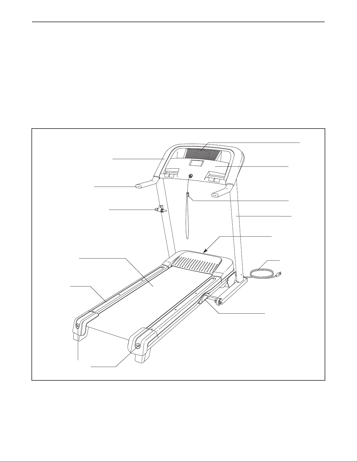
Accessory Tray
Handrail
Storage Latch
®
al. To help us assist you, note the product model
u
umber and serial number before contacting us. The
n
model number and the location of the serial number
decal are shown on the front cover of this manual.
To avoid a registration fee for any service needed
under warranty, you must register the treadmill at
www.iconservice.com/registration.
Before reading further, please review the drawing
below and familiarize yourself with the labeled parts.
Fan
Console
Key/Clip
Upright
Walking Belt
Foot Rail
Rear Roller
Adjustment Bolts
Reset/Off
Circuit Breaker
Power Cord
Platform Cushion
5
ASSEMBLY
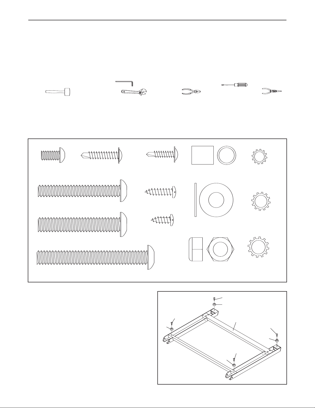
#8 x 1/2" Ground
Screw (11)–2
3/8" Lock Nut
(47)–4
#8 x 3/4" Screw (2)–4
3/8" x 2 1/4" Bolt (40)–4
3/8" Flat Washer
(33)–2
5/16" x 2 1/4" Bolt (20)–4
Wheel Spacer
(44)–4
1/4" x 1/2"
Bolt (22)–2
#8 x 3/4"
Tek Screw (38)–4
#10 x 1" Tek Screw (27)–2
3/8" Star Washer
(7)–4
1/4" Star Washer
(21)–2
5/16" Star
Washer (19)–4
3/8" x 3" Bolt (32)–4
To hire an authorized service technician to assemble the treadmill, call 1-800-445-2480. Assembly requires two persons.
the packing materials until assembly is completed. Note: The underside of the treadmill walking belt is coated
with high-performance lubricant. During shipping, lubricant may be transferred to the top of the walking belt or to
the shipping carton. This is a normal condition and does not affect treadmill performance. If there is lubricant on
top of the walking belt, wipe it off with a soft cloth and mild, non-abrasive cleaner.
Assembly requires the included hex keys and your own Phillips screwdriver , rubber
mallet , adjustable wrench , wire cutters , and needlenose pliers .
For help identifying the assembly hardware, see the drawings below. The number in parentheses below each
drawing is the key number of the part, from the PART LIST near the end of the manual. The number following the
parentheses is the quantity needed for assembly.
preattached to one of the parts to be assembled. Extra hardware may be included. To avoid damaging
plastic parts, do not use power tools for assembly.
Set the treadmill in a cleared area and remove the packing materials; do not dispose of
Note: If a part is not in the parts bag, check to see if it is
1. Orient the Base (48) as shown. Attach the four
Base Pads (37) to the Base with four #8 x 3/4"
Tek Screws (38).
1
37
6
38
38
37
48
38
37
38
37
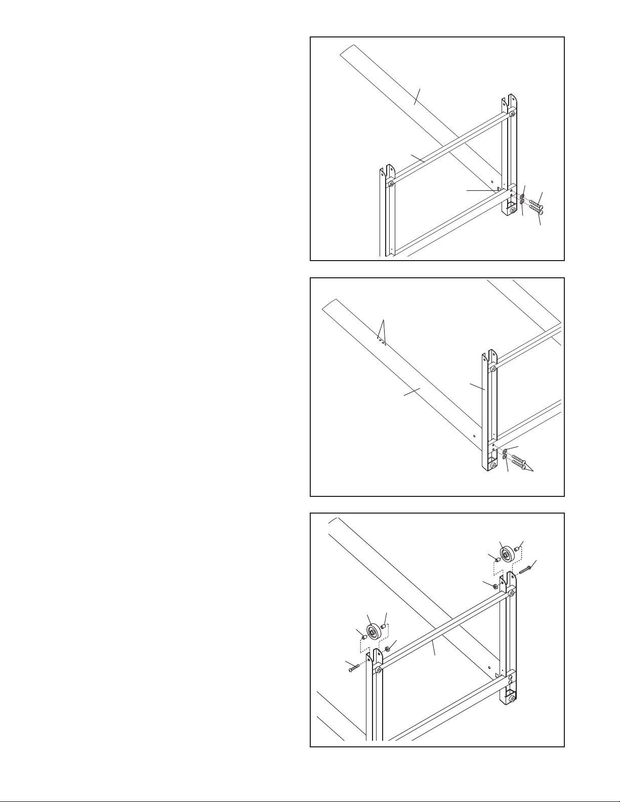
2. Orient the Base (48) as shown.
dentify the Right Upright (36), which has a
I
square hole near the lower end.
Orient the Right Upright (36) as shown, and
attach it to the Base (48) with two 3/8" x 2 1/4"
Bolts (40) and two 3/8" Star Washers (7);
fully tighten the Bolts yet.
do not
2
6
3
48
3. Orient the Left Upright (31) as shown, and attach
it to the Base (48) with two 3/8" x 2 1/4" Bolts
(40) and two 3/8" Star Washers (7);
tighten the Bolts yet.
do not fully
Square
Hole
3
Latch
Holes
48
31
7
40
7
40
7
40
7
4. Attach a Wheel (45) to each side of the Base
(48) with a 3/8" x 3" Bolt (32), two Wheel
Spacers (44), and a 3/8” Lock Nut (47) as
shown. Do not overtighten the Bolts; the
Wheels should turn freely.
4
44
45
32
44
45
44
47
44
47
48
32
7
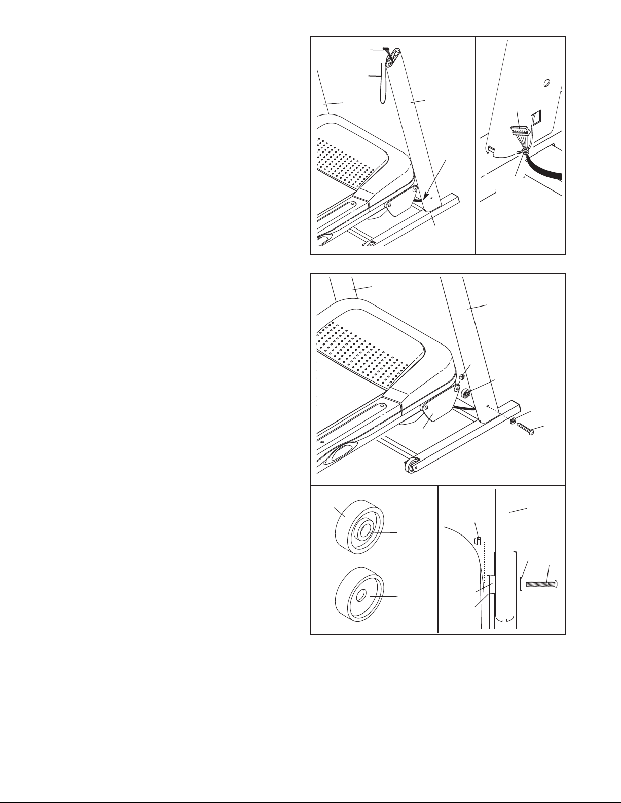
5. Raise the Uprights (31, 36) so that the Base (48)
is flat on the floor and positioned as shown.
5
8
2
Cut the tie holding the Upright Wire (28) in a bundle.
ee the far right drawing. Wrap the wire tie in the
S
Right Upright (36) around the end of the Upright
Wire (28). Then, pull the other end of the wire tie
until the Wire Harness is extending from the
upper end of the Right Upright.
Make sure that the end of the Upright Wire
(28) does not fall into the Right Upright (36).
6. Raise the Uprights (31, 36).
See the left inset drawing. Identify the two
Frame Spacers (34). Open the included packet
of grease, and apply grease to both sides of both
Frame Spacers. Then, identify the outer side of
each Frame Spacer.
Hold the Frame Spacer (34) between the Right
Upright (36) and the Lift Frame (59), with the
outer side of the Frame Spacer facing the
Right Upright. Attach the Right Upright to the
Lift Frame with a 3/8" x 3" Bolt (32), a 3/8" Flat
Washer (33), and a 3/8” Lock Nut (47); do not
fully tighten the Bolt yet.
Wire Tie
6
6
59
3
48
28
Large
Hole
Wire
Tie
36
47
34
33
32
1
3
31
34
Outer
Side
Inner
Side
47
34
59
33
36
32
8
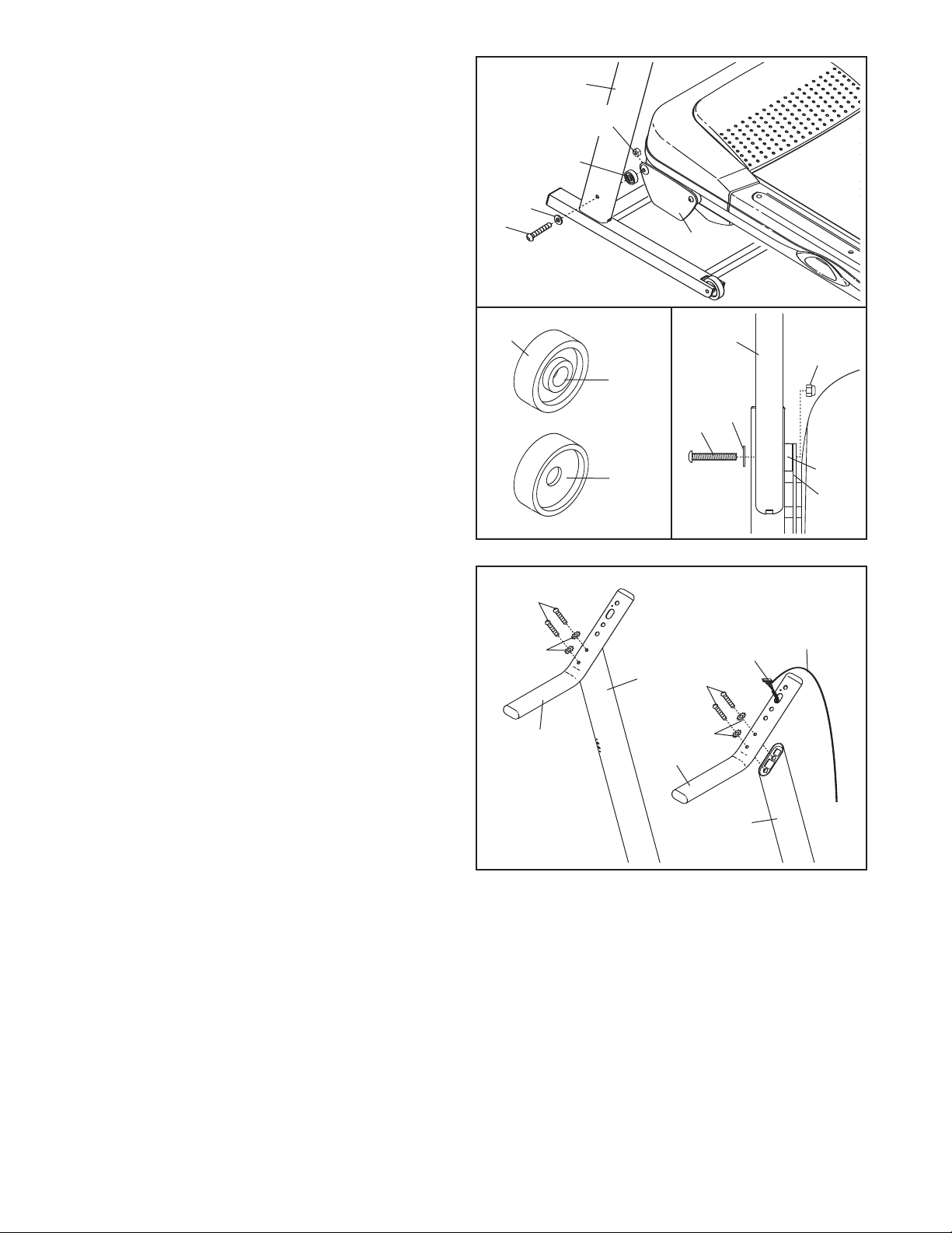
ee the left inset drawing.Identify the outer
7.S
side of the remaining Frame Spacer (34).
7
31
Hold the Frame Spacer (34) between the Left
Upright (31) and the Lift Frame (59), with the
uter side of the Frame Spacer facing the
o
Left Upright. Attach the Left Upright to the Lift
Frame with a 3/8" x 3" Bolt (32), a 3/8" Flat
Washer (33), and a 3/8” Lock Nut (47);
fully tighten the Bolt yet.
do not
32
34
47
34
3
3
59
31
Outer
Side
Inner
Side
32
33
47
34
59
8. Route the Upright Wire (28) through one of the
Handrails (18) as shown. If necessary, use
needlenose pliers to help pull out the Upright
Wire. Remove the wire tie from the Upright Wire.
Attach the Handrail (18) to the Right Upright (36)
with two 5/16" x 2 1/4" Bolts (20) and two 5/16"
Star Washers (19). Be careful not to pinch the
Upright Wire (28).
Attach the other Handrail (18) to the Left Upright
(31) with two 5/16" x 2 1/4" Bolts (20) and two
5/16" Star Washers (19).
8
20
19
18
31
20
19
18
36
28
Wire Tie
9
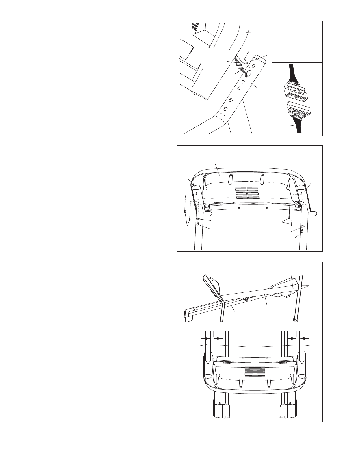
9. While another person holds the Console Base
(26) near the right Handrail (18), attach the
round wire on the Console Base to the right
g
Handrail with a #8 x 1/2" Ground Screw (11).
Connect the wire harness on the Console Base
(26) to the Upright Wire (28).
drawing. The connectors should slide together easily and snap into place. If they do
not, turn one connector and try again. IF THE
CONNECTORS ARE NOT CONNECTED PROPERLY, THE CONSOLE MAY BE DAMAGED
WHEN THE POWER IS TURNED ON.
Insert the wires into the Console Base (26) as
10.
you set the Console Base on the Handrails. Be
careful not to pinch the wires.
two 1/4" x 1/2" Bolts (22) with 1/4" Star Washers
(21) into the Handrails and the Console Base;
do not tighten the Bolts yet.
See the inset
Next, thread
9
10
18
Wire
Harness
26
28
Front View
11
2
18
6
Ground
Wire
28
18
Attach the Console Base (26) to the Handrails
(18) with four #8 x 3/4" Screws (2). Then,
tighten the two 1/4" x 1/2" Bolts (22).
11. Lower the Uprights (31, 36).
See the inset drawing. Position the Uprights
(31, 36) so that the Frame (74) is centered between the Uprights.
Firmly tighten the 3/8" x 3" Bolts (32) and then
the 3/8" x 2 1/4" Bolts (40) on each side of the
treadmill. Do not overtighten the 3/8" x 3"
Bolts.
11
21
2
31
22
Side View
31, 36
74
View from Above
74
2
21
22
32
40
36
10
 Loading...