


Model No. GGSY49230
Serial No.
Write the serial number in the space above for reference.
Serial Number Decal (Under Seat)
QUESTIONS?
As a manufacturer, we are committed to providing complete customer satisfaction. If you have questions, or find that there are missing or damaged parts, we will guarantee you complete satisfaction through direct assistance from our factory.
TO AVOID UNNECESSARY DELAYS, PLEASE CALL DIRECT TO OUR TOLL-FREE CUSTOMER HOT LINE. The trained technicians on our customer hot line will provide immediate assistance, free of charge to you.
CUSTOMER HOT LINE:
1-800-999-3756
Mon.–Fri., 6 a.m.–6 p.m. MST
 CAUTION
Read all precautions and instructions in this manual before using this equipment. Save this manual for future reference.
USER'S MANUAL
TABLE OF CONTENTS
IMPORTANT PRECAUTIONS . . . . . . . . . . . . . . . . . . . . . . . . . . . . .2 BEFORE YOU BEGIN . . . . . . . . . . . . . . . . . . . . . . . . . . . . . . . . . .3 ASSEMBLY . . . . . . . . . . . . . . . . . . . . . . . . . . . . . . . . . . . . . . . . . .4 ADJUSTMENTS . . . . . . . . . . . . . . . . . . . . . . . . . . . . . . . . . . . . . .22 WEIGHT RESISTANCE CHART . . . . . . . . . . . . . . . . . . . . . . . . . .24 TROUBLESHOOTING AND MAINTENANCE . . . . . . . . . . . . . . . .25 CABLE DIAGRAMS . . . . . . . . . . . . . . . . . . . . . . . . . . . . . . . . . . .26 ORDERING REPLACEMENT PARTS . . . . . . . . . . . . . . .Back Cover LIMITED WARRANTY . . . . . . . . . . . . . . . . . . . . . . . . . .Back Cover
Note: A PART IDENTIFICATION CHART and a PART LIST/ EXPLODED DRAWING are attached in the center of this manual.

IMPORTANT PRECAUTIONS
 WARNING: To reduce the risk of serious injury, read the following important precautions before using the weight system.
1.Read all instructions in this manual and in the accompanying literature before using the weight system.
2.It is the responsibility of the owner to ensure that all users of the weight system are adequately informed of all precautions.
3.The weight system is intended for home use only. Do not use the weight system in any commercial, rental, or institutional setting.
4.Use the weight system only on a level surface. Cover the floor beneath the weight system to protect the floor.
5.Make sure all parts are properly tightened each time the weight system is used. Replace any worn parts immediately.
6.Keep children under 12 and pets away from the weight system at all times.
7.Keep hands and feet away from moving parts.
8.Always wear athletic shoes for foot protection.
9.The weight system is designed to support a a maximum user weight of 300 pounds.
10.Always stand on the foot plate when performing an exercise that could cause the weight system to tip.
11.Always disconnect the lat bar from the weight system when performing an exercise that does not use the lat bar.
12.Make sure that the cables remain on the pulleys at all times. If the cables bind while you are exercising, stop immediately and make sure that the cables are on all of the pulleys.
13.Never release the press arm, butterfly arms, military press arm, leg lever, leg press plate, lat bar or nylon strap when weights are raised. The weights will fall with great force.
14.Keep your hands away from the assist upright when the assist arm is being used. Your hand could become pinched between the assist upright and the assist arm.
15.Keep your hands away from the leg press upright when the military press arm is being used. Your hand could become pinched between the leg press upright and the military press arm.
16.Always be sure that your body weight is fully supported by the dip arms or the pull-up arms before kneeling on the assist arm. The assist arm can drop quickly when your body weight is placed on it.
17.If you feel pain or dizziness at any time while exercising, stop immediately and begin cooling down.
18.The decals shown below have been placed on the weight system in the locations shown on page 3. If a decal is missing or illegible, call our toll-free Customer Hot Line at 1-800-999-3756 and order a free replacement decal. Apply the decal in the location shown.
Keep hands and fingers clear of this area.
Warning Decal 2
• Keep clear of this area.
Warning Decal 1 |
Warning Decal 3 |
 WARNING: Before beginning this or any exercise program, consult your physician. This is especially important for persons over the age of 35 or persons with pre-existing health problems. Read all instructions before using. ICON assumes no responsibility for personal injury or property damage sustained by or through the use of this product.
2

BEFORE YOU BEGIN
Thank you for selecting the versatile GOLD’S GYM |
questions, please call our Customer Service |
XR60 weight system. The weight system offers a |
Department toll-free at 1-800-999-3756, Monday |
selection of weight stations designed to develop every |
through Friday, 6 a.m. until 6 p.m. Mountain Time |
major muscle group of the body. Whether your goal is |
(excluding holidays). To help us assist you, please note |
to tone your body, build dramatic muscle size and |
the product model number and serial number before |
strength, or improve your cardiovascular system, the |
calling. The model number is GGSY49230. The serial |
weight system will help you to achieve the specific |
number can be found on a decal attached to the |
results you want. |
weight system (see the front cover of this manual). |
For your benefit, read this manual carefully before |
Before reading further, please review the drawing |
using the weight system. If you have additional |
below and familiarize yourself with the labeled parts. |
|
|
Lat Bar |
ASSEMBLED |
||
DIMENSIONS: |
|||
|
|||
|
Height: |
78 in. |
|
|
Width: |
110 in. |
|
|
Length: 92 in. |
||
Pull-up Handles |
High Pulley Station |
||
|
|
||
Warning Decal 1 |
Butterfly Arms |
||
|
|
||
|
Warning Decal 1 |
||
Dip Handles |
Military Press Arm |
||
|
|
||
|
|
Backrests |
|
|
|
Leg Press |
|
|
|
Plate |
|
|
Warning Decal 2 |
||
Assist Arm |
|
Press Arm |
|
|
|
Leg Lever |
|
|
Warning Decal 3 |
||
Weight Stacks |
|
|
|
|
Low Pulley |
||
|
|
Station |
|
Weight Pin |
|
Foot Plate |
|
|
3 |
|
|

ASSEMBLY
Before beginning assembly, carefully read the following information and instructions:
•Place all parts of the weight system in a cleared area and remove the packing materials; do not dispose of the packing materials until assembly is completed.
•The assembly is broken into four stages: 1) frame assembly, 2) arm assembly, 3) cable assembly, and 4) seat and backrest assembly. The hardware for each stage is packaged separately.
•Wait until you begin each assembly stage to open the parts bag labeled for that assembly stage.
•For help identifying the small parts used in assembly, use the PART IDENTIFICATION
CHART located in the center of this manual.
Note: Some small parts may have been preattached for shipping. If a part is not in the parts bag, check to see if it has been pre-attached.
•As you assemble the weight system be sure that all parts are oriented as shown in the drawings.
•Tighten all parts as you assemble them, unless instructed to do otherwise.
THE FOLLOWING TOOLS (NOT INCLUDED) ARE REQUIRED FOR ASSEMBLY:
• Two (2) adjustable wrenches
• One (1) standard screwdriver
• One (1) phillips screwdriver
• One (1) rubber mallet
•Lubricant, such as grease or petroleum jelly, and soapy water will also be needed.
Assembly will be more convenient if you have the following tools: A socket set, a set of open-end or closed-end wrenches, or a set of ratchet wrenches.
FRAME ASSEMBLY
1. Before beginning assembly, be sure that |
1 |
|
|
you have read and understand the infor- |
|
|
|
|
|
|
|
mation in the box above. |
|
|
|
Locate and open the parts bag labeled |
|
|
|
“FRAME ASSEMBLY.” |
|
|
|
Press two 50mm Square Outer Caps (51) |
|
|
|
onto the Stabilizer (5). Press a 50mm |
|
|
|
Square Inner Cap (27) into the Base (4). |
|
|
|
Insert six M8 x 65mm Carriage Bolts (1) up |
|
11 |
|
through the Stabilizer (5). Insert two M8 x |
51 |
5 |
|
65mm Carriage Bolts up through the Base |
|
|
8 |
(4). |
|
|
|
Attach the Base (4) to the Stabilizer (5) with |
8 |
|
1 |
two M8 x 70mm Bolts (11), two M8 Washers |
|
|
|
|
|
|
|
(8), and two M8 Nylon Locknuts (3). Do not |
|
|
|
tighten the Nylon Locknuts yet. |
|
|
3 |
|
|
|
|
|
|
1 |
4 |
|
51 |
|
|
|
|
|
|
|
|
|
1 |
|
|
|
27 |
4

FRAME ASSEMBLY
2. Slide the Assist Upright (74) and the Leg |
2 |
|
|
Press Upright (56) onto the indicated M8 x |
|
27 |
|
|
|
||
65mm Carriage Bolts (1) in the Stabilizer (5). |
|
|
|
|
|
|
|
The high side of the brackets on the Assist |
|
27 |
|
Upright and Leg Press Upright should be |
|
|
|
on the side shown. Hand tighten four M8 |
|
87 |
|
Nylon Locknuts (3) onto the Carriage Bolts. |
|
High Sides |
|
|
|
||
Do not tighten the Nylon Locknuts yet. |
|
91 |
of Brackets |
|
74 |
|
|
Press two 50mm Square Inner Caps (27) into |
|
|
|
|
|
56 |
|
the Leg Press Upright (56). Press a 50mm |
|
|
|
|
|
|
|
Square Inner Cap into the Assist Upright (74). |
|
27 |
|
Attach the Rubber Bumper (91) to the Leg |
|
|
|
Press Upright (56) with the M4 x 16mm Self- |
|
|
|
tapping Screw (87). |
|
|
|
|
|
|
3 |
|
|
3 |
|
|
|
3 |
|
|
|
|
5 |
|
3 |
|
1 |
|
|
|
|
|
|
1 |
|
3. Slide the Front Upright (42) onto the M8 x |
3 |
|
|
65mm Carriage Bolts (1) in the Base (4). |
|
|
|
|
|
|
|
Hand tighten an M8 Nylon Locknut (3) onto |
|
|
|
each Carriage Bolt. Do not tighten the |
|
|
|
Nylon Locknuts yet. |
|
|
|
Press a 25mm Square Inner Cap (6) into the |
|
|
|
Front Upright (42). |
|
|
|
|
|
|
42 |
|
|
|
6 |
|
|
|
3 |
|
|
4 |
|
|
|
|
1 |
5

FRAME ASSEMBLY
4. Press a 50mm Square Inner Cap (27) into the |
4 |
11 |
|
end of the Top Frame (55). Press a 45mm |
|
||
|
113 |
||
|
55 |
||
Square Inner Cap (44) into each end of the |
|
8 |
|
crossbar on the Top Frame. Press two 25mm |
|
44 |
|
|
|
||
Inner Caps (113) into the top of the crossbar. |
27 |
|
|
|
3 |
|
|
Attach the Top Frame (55) to the Assist |
|
|
|
|
|
Crossbar |
|
Upright (74) and the Leg Press Upright (56) |
|
|
|
with two M8 x 70mm Bolts (11) and two M8 |
|
|
44 |
|
|
|
|
Nylon Locknuts (3). |
|
|
|
Attach the Top Frame (55) to the Front |
11 |
|
3 |
Upright (42) with two M8 x 70mm Bolts (11), |
|
||
|
|
||
|
|
|
|
two M8 Washers (8), and two M8 Nylon |
|
|
|
Locknuts (3). |
|
|
|
Do not tighten the M8 Nylon Locknuts (3) |
|
56 |
42 |
yet. |
|
|
|
|
|
74 |
|
5. Slide the Rear Seat Frame (100) onto the |
|
|
|
indicated M8 x 65mm Carriage Bolts (1) in the |
|
|
|
Stabilizer (5). Hand tighten two M8 Nylon |
|
|
|
Locknuts (3) onto the Carriage Bolts. Do not |
5 |
1 |
|
tighten the Nylon Locknuts yet. |
|
||
|
|
||
|
|
|
100 |
Attach the other end of the Rear Seat Frame |
|
11 |
|
(100) to the Leg Press Upright (56) with two |
|
|
|
|
|
3 |
|
M8 x 70mm Bolts (11), two M8 Washers (8), |
|
56 |
|
|
|
||
and two M8 Nylon Locknuts (3). |
|
8 |
|
|
|
|
|
Attach the Handle (82) to the Rear Seat |
|
|
|
Frame (100) with two M8 x 65mm Carriage |
3 |
3 |
|
Bolts (1) and two M8 Nylon Locknuts (3). |
|
82 |
|
|
|
|
|
Tighten all Nylon Locknuts used in steps |
|
1 |
5 |
1–5. |
|
||
|
|
||
6. Set two Weight Bumpers (19) on the bracket |
6 |
|
|
on the Base (4) as shown. Set two Weight |
|
|
|
Pin |
|
|
|
Bumpers (19) on the bracket on the Stabilizer |
|
|
|
Grooves |
|
||
(5). Make sure the flat side of the Bumpers |
|
|
|
are on the bottom. |
|
|
|
Stack ten Weights (25) onto the bracket on |
|
25 |
|
the Stabilizer (5). Stack eight Weights onto |
|
|
|
25 |
|
|
|
the bracket on the Base (4). Be sure that the |
|
|
|
|
5 |
|
|
pin grooves are all on the same side of |
|
|
|
each stack of Weights. |
|
19 |
Pin |
|
|
Bracket |
|
Be careful not to tip either stack of |
|
Grooves |
|
|
|
|
|
Weights (25) until step 8 is complete. |
|
4—Bracket |
19 |
|
|
||
6 |
|
|
|

FRAME ASSEMBLY
7. Press a Weight Tube Bumper (64) into the |
7 |
|
|
end of the Short Weight Tube (108). Insert the |
Holes |
||
|
|||
Weight Tube into the front stack of Weights |
|
|
|
(25). Be sure that the pin on the Weight |
|
62 |
|
Tube is sitting in the pin groove in the top |
|
||
Weight. |
|
|
|
Lubricate the inside of the holes in a Top |
|
|
|
Weight (65). Set the Top Weight onto the front |
|
|
|
stack of Weights (25). Insert both Long |
|
|
|
Weight Guides (62) into the stack of Weights. |
|
|
|
Be sure that the holes in the Weight |
|
|
|
Guides are at the top, as shown. |
|
|
|
|
|
65 |
|
|
|
Lubricate |
|
|
|
Pin |
|
|
|
108 |
|
|
|
64 |
|
|
|
Pin Groove |
|
|
|
25 |
|
8. Press a Weight Tube Bumper (64) into the |
8 |
|
|
end of the Long Weight Tube (63). Insert the |
Holes |
||
|
|||
Weight Tube into the rear stack of Weights |
|
|
|
(25). Be sure that the pin on the Weight |
|
73 |
|
Tube is sitting in the pin groove in the top |
|
||
|
|
||
Weight. |
|
|
|
Lubricate the inside of the holes in the other |
|
|
|
Top Weight (65). Set the Top Weight onto the |
|
|
|
rear stack of Weights (25). Insert both Short |
|
|
|
Weight Guides (73) into the stack of Weights. |
|
|
|
Be sure that the holes in the Weight |
|
|
|
Guides are at the top, as shown. |
|
Lubricate |
|
|
|
||
|
|
65 |
|
|
|
Pin |
|
|
|
63 |
|
|
|
64 |
|
|
|
Pin Groove |
|
|
|
25 |
|
7 |
|
|

FRAME ASSEMBLY
ARM ASSEMBLY
9. |
Attach the upper ends of the Short Weight |
9 |
61 |
|
61 |
|
|
Guides (73) to the Top Frame (55) with an M8 x |
3 |
|
|||
|
|
|
||||
|
150mm Bolt (60), two 19.5mm Spacers (61), |
|
|
|
|
3 |
|
and an M8 Nylon Locknut (3). |
60 |
|
|
|
55 |
|
|
|
|
|
|
|
|
Attach the upper ends of the Long Weight |
|
|
|
|
|
|
Guides (62) to the Top Frame (55) in the same |
|
|
|
|
|
|
manner. |
73 |
|
60 |
|
|
|
|
|
|
|||
|
|
|
|
62 |
|
|
10. |
Locate and open the parts bag labeled |
|
|
|
|
|
|
“ARM ASSEMBLY.” |
|
|
|
|
|
|
Make sure there is a Bushing (98) in each side |
|
|
|
|
|
|
of the Stabilizer (5). Press three 50mm Square |
10 |
|
|
|
|
|
Inner Caps (27) into the ends of the Leg Press |
|
|
|
27 |
|
|
|
|
|
95 |
||
|
Arm (96). |
|
|
|
Welded |
|
|
|
|
|
|
||
|
|
|
|
|
|
|
|
Lubricate an M10 x 80mm Bolt (67) with grease. |
|
|
|
|
Tube |
|
|
|
|
|
|
|
|
Attach the Leg Press Arm (96) to the Stabilizer |
|
|
|
|
|
|
(5) with the Bolt and an M10 Nylon Locknut |
|
|
96 |
|
97 |
|
(21). Do not overtighten the Locknut; the Leg |
|
|
|
|
|
|
|
|
|
21 |
27 |
|
|
Press Arm must be able to pivot freely. |
|
|
|
||
|
|
|
|
|
|
|
|
Align the welded tubes on the Leg Press Plate |
|
|
|
|
Lubricate |
|
|
|
98 |
|
|
|
|
(95) with a set of holes in the Leg Press Arm |
|
|
|
|
|
|
|
|
|
27 |
|
|
|
(96). Attach the Leg Press Plate to the Leg |
|
|
|
67 |
|
|
Press Arm with the Press Pin (97). |
|
|
|
98 |
|
|
|
|
|
5 |
|
|
|
|
|
|
|
|
|
11. |
Press a 22mm Plastic Bushing (90) onto each |
11 |
|
|
|
|
|
welded spacer on the Press Frame (17). Slide |
|
|
|
Pulleys |
|
|
|
|
|
|
||
|
the Press Frame into place onto the Base (4). |
|
|
|
17 |
must be on |
|
Note: This will be a tight fit; the Plastic |
|
|
|
|
this side |
|
Bushings should fit snugly over the ends of |
|
|
|
|
|
|
the indicated tube in the Base. Make sure |
|
|
|
Lubricate |
|
|
that the pulleys are on the side shown. |
|
|
|
|
|
|
Lubricate the M10 x 198mm Bolt (59) with |
|
|
|
|
59 |
|
|
|
|
|
|
|
|
grease. Attach the Press Frame (17) to the |
|
|
21 |
Welded Spacers |
|
|
Base (4) with the Bolt and an M10 Nylon |
|
|
|||
|
|
|
|
|||
|
Locknut (21). Do not overtighten the |
4 |
|
|
|
|
|
Locknut; the Press Frame must be able to |
Tube |
|
|
90 |
|
|
pivot easily. |
|
|
|
|
|
|
|
|
|
|
|
|
8

ARM ASSEMBLY
12.Press a 25mm Round Inner Cap (49) into one of the Press Arms (46). Press a 45mm Square Inner Cap (44) into the Press Arm.
Attach the Press Arm (46) to one side of the Press Frame (17) with two M8 x 63mm Bolts (22) and two M8 Nylon Locknuts (3).
Assemble the other Press Arm (46) in the same manner.
13.Identify the Right Arm (48) and the Left Arm (47). Note the position of the welded bracket on each Arm. Arm identification is very important for step 14.
Press a 70mm Plastic Bushing (89) into the Right Arm (48). Attach a “V”-Pulley (50) and a Long Cable Trap (31) to the Right Arm with an M10 x 58mm Bolt (86) and an M10 Nylon Locknut (21). Do not tighten the Locknut yet.
Assemble the Left Arm (47) in the same manner.
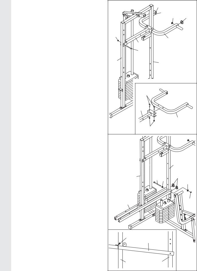
14.Lubricate both axles on the Top Frame (55).
Slide the Right Arm (48) onto the right axle.
Note: Be careful not to confuse the Right Arm with the Left Arm (47); refer to step 13 to identify the Right Arm. Be sure that the upper end of the Right Arm is behind the indicated bracket on the Top Frame (55).
Tap two 25mm Retainers (69) and a 25mm Round Cover Cap (70) onto the axle. Be sure that the teeth on the Retainers bend toward the Round Cover Cap, as shown in the inset drawing.
Attach the Left Arm (47) in the same manner.
Press two 45mm Square Inner Caps (44) into the lower ends of the Right and Left Arms (47, 48). Wet the lower end of each Arm with soapy water. Slide a Large Foam Pad (45) onto the lower end of each Arm.
9
12 |
|
|
44 |
49 |
|
|
|
|
|
|
|
|
|
46 |
|
|
22 |
|
|
|
46 |
|
|
|
|
|
|
3 |
|
|
|
|
17 |
|
13 |
86 |
|
|
|
|
31 |
|
|
|
|
50 |
|
|
|
|
89 |
|
|
47 |
|
21 |
Welded |
|
|
|
|
Brackets |
|
|
|
48 |
|
|
|
14 |
|
|
|
|
|
|
55 |
Bracket |
|
|
|
|
|
|
|
|
|
|
47 |
|
|
|
Lubricate |
|
|
|
|
Axle |
|
|
48 |
|
|
|
|
|
|
69 |
|
|
|
|
|
45 |
|
|
|
70 |
|
|
|
|
|
44 |
|
44 |
|
|
|
|
45 |
|
Axle |
|
|
|
|
|
|
|
|
|
|
69 |
|
|
|
|
70 |
ARM ASSEMBLY
15. See the inset drawing. Attach the Military |
15 |
32 |
|
|
Press Arm (84) to the Pivot Arm (101) with |
|
|
||
|
|
|
||
|
|
|
|
|
two M8 x 55mm Bolts (33) and two M8 Nylon |
|
|
49 |
|
Locknuts (3). |
|
|
49 |
32 |
Press two 38mm Square Inner Caps (32) into |
|
|
|
|
the Military Press Arm (84). Press two 25mm |
|
|
|
|
Round Inner Caps (49) into the Military Press |
21 |
|
|
|
Arm. |
|
|
84 |
|
Attach the Pivot Arm (101) to the Assist |
101 |
|
|
|
67 |
|
|
|
|
Upright (74) with an M10 x 80mm Bolt (67) |
|
|
|
|
|
|
|
|
|
and an M10 Nylon Locknut (21). Do not over- |
|
|
|
|
tighten the Locknut; the Pivot Arm must |
74 |
56 |
|
|
be able to pivot easily. |
|
|
|
|
|
|
33 |
|
|
|
101 |
|
|
|
|
|
|
84 |
|
|
|
3 |
|
|
16. Press two 25mm x 50mm Inner Caps (107) |
16 |
|
|
|
into the Assist Arm (105). |
|
|
|
|
|
|
|
|
|
Attach the Assist Arm (105) to the Leg Press |
|
|
|
|
Upright (56) with an M10 x 150mm Bolt (106), |
|
|
|
|
two M10 Washers (9), and an M10 Nylon |
|
|
|
|
Locknut (21). Do not overtighten the |
|
|
56 |
|
Locknut; the Assist Arm must be able to |
|
|
|
|
|
|
|
|
|
pivot easily. |
|
|
|
|
|
74 |
106 |
107 |
|
Note: (See the inset drawing.) The Assist |
9 |
9 |
||
|
|
|
||
Arm must be attached to the lowest hole in |
|
|
|
|
|
|
|
|
|
the Leg Press Upright (56). The Assist Arm |
|
|
|
|
must also be below the welded bracket on |
|
|
|
|
the Assist Upright (74). |
105 |
|
|
21 |
|
|
|
|
|
|
Bracket |
|
|
|
|
|
105 |
|
|
|
74 |
56 |
|
|
10
 Loading...