

Page 1

GETINGE 9100-SERIES
TECHNICAL MANUAL
6001341502
Page 2

Page 3

Contents
PREFACE...................................................................................................................... 5
SAFETY PRECAUTIONS................................................................................................ 6
Important................................................................................................................ 6
Isolator switch......................................................................................................... 6
In an emergency..................................................................................................... 7
Make sure that the assembly and installation is carried out:.................................... 7
When the work is complete, check that................................................................... 7
Product liability........................................................................................................ 7
Attention symbols................................................................................................... 8
INTRODUCTION............................................................................................................ 9
Area of application.................................................................................................. 9
General Description................................................................................................. 9
Washer-disinfector options and selections.............................................................. 9
Performance Characteristics................................................................................. 12
CONTROL PANEL....................................................................................................... 19
OP30 panel........................................................................................................... 19
Display panel rules................................................................................................ 23
OP10 panel......................................................................................................... 107
ALARM MANAGEMENT............................................................................................. 108
Error indicators................................................................................................... 108
Acknowledging an alarm..................................................................................... 109
PREVENTIVE MAINTENANCE.................................................................................... 121
General............................................................................................................... 121
Function check................................................................................................... 122
Loading of System Program and Application Program........................................ 123
Load the back up in the "Flash Prom" to the PACS............................................. 125
Changing of operating language.......................................................................... 125
Cold and warm start of PACS 3500.................................................................... 126
Softstart.............................................................................................................. 127
Adjusting analog input......................................................................................... 129
Pressure transmitter for DISCHARGE PRESSURE (0-2.5 bar)............................. 134
Temperature sensors.......................................................................................... 135
Pressure differential transmitter for drying unit (0-10 mbar).................................. 135
DOSING..................................................................................................................... 136
Replacing a hose in the dosing pump................................................................. 136
Hose selection.................................................................................................... 137
Setting detergent and rinse-aid quantities........................................................... 138
Flow monitoring.................................................................................................. 139
Starting up.......................................................................................................... 139
DOORS...................................................................................................................... 140
Door switches, position and operation................................................................ 140
Adjusting the pressure stabilizer.......................................................................... 141
Adjusting the limit switch..................................................................................... 142
Adjusting safety line breaker................................................................................ 147
Overheating protection (only on electrically heated washer-disinfectors).............. 148
Page 3 of 166
<Doc_TEC><Doc_6001341502><Rel.A><Lang_en>
Page 4

Dryer (electrically heated).................................................................................... 149
Printer (optional).................................................................................................. 150
LIST OF COMPONENTS............................................................................................ 152
Detergent system................................................................................................ 156
Water system, steam heated............................................................................... 157
Electric heating................................................................................................... 158
Drying system, electrically heated........................................................................ 159
Booster tank, steam heated................................................................................ 160
GLOSSARY............................................................................................................... 162
ADDRESSES............................................................................................................. 163
Page 4 of 166
<Doc_TEC><Doc_6001341502><Rel.A><Lang_en>
Page 5
PREFACE
This manual is intended for users of products from Getinge Disinfection AB.
The user manual describes the design and operation of the machine and the maintenance for which the
user is responsible. The installation manual describes the machine's installation. The technical manual
describes necessary information for operators and maintenance personnel. The information in the manual
must be complied with to ensure safe and error-free operation.
Read the manual before use.
Users must read through the manual before using the machine for the first time, as well as familiarizing
themselves with the operation of the machine and its safety instructions. Operators and maintenance
personnel must have completed training through Getinge Academy.
The information in this manual describes the machine as dispatched from Getinge Disinfection AB. There
may be differences due to customization for customers or countries.
The machine is accompanied by the following documentation:
• User manual
• Installation manual
• Declaration of conformity
The following documentation is supplied on CD:
• User manual
• Installation manual
• Electrical diagrams
• Program sheets
The following documentation shall be provided by the sales company to the end-user on request:
• Technical manual
• Spare parts list
Getinge Disinfection AB reserves the right to change the specification and design without prior notice.
The information in this manual was up-to-date on the date that the manual was issued.
© Copyright
The content of this manual must not be copied, in
whole or in part, without written consent from
Getinge Disinfection AB.
Page 5 of 166
<Doc_TEC><Doc_6001341502><Rel.A><Lang_en>
Page 6

SAFETY PRECAUTIONS
This machine has a number of built-in safety devices.
To avoid injury, it is highly important not to bypass these safety devices.
If the equipment is used in a manner not specified by the manufacturer this can impair the safety
equipment on the machine.
Operators and maintenance personnel must undergo safety training for the machine. All personnel who
handle chemicals for washing and disinfection must understand the washing process, possible health
hazards and ways of detecting leaks of toxic chemicals.
Operators and maintenance personnel must undergo regular training in the operation and maintenance of
the equipment. There must be a documented list of personnel who have been trained to use the
machine. Trained personal must be tested to verify the training program.
Important
• Take care when handling the chemical agents used in the machine. Read the instructions on
the pack or contact the manufacturer before using the machine for instructions about:
o
if the agent comes into contact with the operator’s eyes or skin or if the vapors are
breathed in, etc.
o
for storage of packs and sorting of empty packs
o
use personal safety equipment such as safety goggles, protective gloves, etc.
• The machine must be connected in accordance with the instructions given in the installation
manual.
• The machine may only be used by adults.
• Installation and servicing may only be done by personnel trained for this machine.
• Never bypass door safety switches.
• Leaks in the system caused by worn seals in the door, for example, must be repaired
immediately.
• Before any welding is done, all cables connected to the control system via connectors and
sockets must be disconnected.
• Before doing any servicing or maintenance work on the machine, isolate it from the electric
power supply and drain all tanks.
• Do not wash down or hose down the machine with water.
• Take care when using corrosive substances.
• Observe safety measures for steam and hot water.
• The machine must not be operated with cladding plates, roof and plinths removed. Doing this
puts at risk the safety and functioning of the machine.
• The electrical cabinet may only be opened by authorized and trained personnel.
• Spare parts may only be obtained from Getinge sales companies.
Isolator switch
The machine must be preceded by a lockable switch for the electric power supply. The switch must be
easily accessible on a wall close to the machine. The installation must conform to and be marked in
accordance with local regulations.
Page 6 of 166
<Doc_TEC><Doc_6001341502><Rel.A><Lang_en>
Page 7
In an emergency
• Press the emergency stop.
• Switch off the main power switch.
• Close shutoff valves in the water and any steam supply lines.
Make sure that the assembly and installation is carried out:
• by qualified personnel.
• in accordance with current local regulations and rules.
To avoid the risk of back injury, this equipment should be assembled and installed
by at least two people.
When the work is complete, check that
• all parts have been installed according to the installation manual.
• all screws have been properly tightened
• there are no sharp edges on any parts that may come into contact with people
• all hoses, pipes and connections are intact and free from defects
• all the functions of the machine are working properly. Adjust if necessary.
• make sure that no electrical wires or hoses are touching any hot surfaces
• check electrical connections both inside the electrical cabinet and to elements
Carry out an Installation Qualification, an Operating Qualification, and a Performance Qualification
according to ISO 15883 before putting the machine into service.
Incorrect use may result in damage to objects and personal injury.
Product liability
Any modification or incorrect use of the equipment without the approval of Getinge Disinfection AB
negates Getinge Disinfection AB’s product liability.
This product was manufactured by:
GETINGE DISINFECTION AB
Ljungadalsgatan 11, Box 1505
SE-351 15 Växjö, Sweden
Page 7 of 166
<Doc_TEC><Doc_6001341502><Rel.A><Lang_en>
Page 8
Attention symbols
Some of the warnings, instructions and advice in this manual are so important that we use the following
special symbols to draw attention to them. The symbols and designs used are:
Risk of injuries or machine damage.
ESD-sensitive equipment.
Live components.
Page 8 of 166
<Doc_TEC><Doc_6001341502><Rel.A><Lang_en>
Page 9

INTRODUCTION
Area of application
Getinge's washer-disinfector in the 9100 series is used in medical services for washing, disinfecting at
intermediate level (A0 = 600 as standard) and drying. The washer-disinfector is used at hospitals to wash,
disinfect and dry items such as carts, containers and equipment (wash basins, bowls and similar items in
stainless steel).
Getinge's washer-disinfector in the 9100 series is used in life science for washing, disinfecting at
intermediate level (A0 = 600 as standard) and drying. The washer-disinfectors are used by animal testing
companies to wash, disinfect and dry items such as transport trolleys, racks, cages and rack equipment.
The containers should be loaded correctly on loading equipment recommended by Getinge Disinfection
AB. The customer is responsible for Installation Qualification, Operating Qualification and Performance
Qualification being performed according to EN ISO 15883 before product usage.
Incorrect use can result in damage to objects and personal injuries.
General Description
The Getinge 9100-series washer-disinfectors are large capacity, jet spray washers for mechanical
washing, intermediate level (A0 value = 600 as standard) thermal disinfection and drying of moisture and
temperature stable hospital carts, sterilization containers, material handling carts, stands and utensils.
The washer-disinfector comes in four different sizes: the 9120, 9125, 9128 and 9122 models.
Model
Door Width Door High Chamber Length /
Load Length
9120 960 (38”) 2000 (80”) 2000 (80”) Health Care (HC)
9125 960 (38”) 2000 (80”) 2500 (98”) Health Care (HC)
9128 960 (38”) 2000 (80”) 2850 (112”) Health Care (HC)
9122 1170 (46”) 2200 (86”) 2200 (86”) Life Science (LS)
Washer-disinfector options and selections
The 9100-series washer-disinfector may be equipped according to the following options and accessories.
Floor Mount or Pit Mount
For a floor-mounted washer-disinfector, ramps are required to access the washer-disinfector. The inner
floor of a pit-mounted washer-disinfector is at the same level as the area's floor.
Horizontal or Inclined Sliding Door
As standard, the door opens horizontally, straight to the side. An inclined sliding door is required if the
unit is mounted in a pit with a width of 1900-2400 mm. The sliding doors open toward the service area.
Right Side or Left Side Service Area
Provide access to components such as plumbing, valves, pumps, tanks, electrical cabinet, etc. The
location of service area on your washer can be located left or right hand.
One or two doors
One door for loading/unloading on the same side, or two doors - one for loading on soiled side and one
for unloading on clean side.
Page 9 of 166
<Doc_TEC><Doc_6001341502><Rel.A><Lang_en>
Page 10

Steam or electric heating
The heating elements for water, drying and the booster tank are heated with the building's steam or
electricity.
Connection for treated water
Connection for treated water in addition to hot and cold water, which are standard.
Dosing pumps for detergent
The washer-disinfector comes as standard with two dosing pumps for detergent for process chemicals,
but a third and fourth can also be installed. This allows the chemical disinfection of e.g. heat-sensitive
objects. All dosing pumps for detergents have flow-regulation.
Water-saving tanks
One or two water-saving tanks can be installed in the service area.
Docking for wash cart
A docking mechanism in the floor to dock wash carts equipped with spray arms.
Booster tank
Tank for the preheated water to be used in the process.
Automatic flushing system for valve rack
The spray system to be used with special carts equipped with this type of spray system.
Cooling system for waste water
Cooling system to adjust the temperature of the waste water that comes from the machine.
Neutralization system for waste water
Neutralization system for adjusting the pH value for the waste water that comes from the machine.
Comes in two versions, time control or pH monitoring.
Conductivity control, final rinse
Conductivity control for the final rinse.
Conductivity control, dosing
Conductivity control for dosage of detergent
Trolley Tilt
The Chamber floor can be tilted in the washing phase so that the water on the items can drip off and the
items can dry faster.
Printer, option 1
Thermal printer that provides a printout of activities in the washer-disinfector during the process at a
preset time.
Printer, option 2
Laser printer
Page 10 of 166
<Doc_TEC><Doc_6001341502><Rel.A><Lang_en>
Page 11

Flow sensor with kalrez seal
Flow sensor with kalrez seal for highly concentrated detergent.
Front panels for service area
Cover plates to conceal the service area. The cover plates have a door for easy access to the space.
Installation kit
• Manometer, stop valve and filter for water and steam connection.
• Air bleeding kit with drainage hose.
Instrument wash
Instrument wash is a program for the washer-disinfector that cleans, disinfects and dries soiled, heavy
surgical instruments. To use this program, you need a wash cart that is suitable for these type of objects.
Ramp
Washers-disinfectors that are floor-mounted come with a split or whole ramp.
NetCom
Netcom connection
Page 11 of 166
<Doc_TEC><Doc_6001341502><Rel.A><Lang_en>
Page 12
Performance Characteristics
Programming may only be done by authorized personnel.
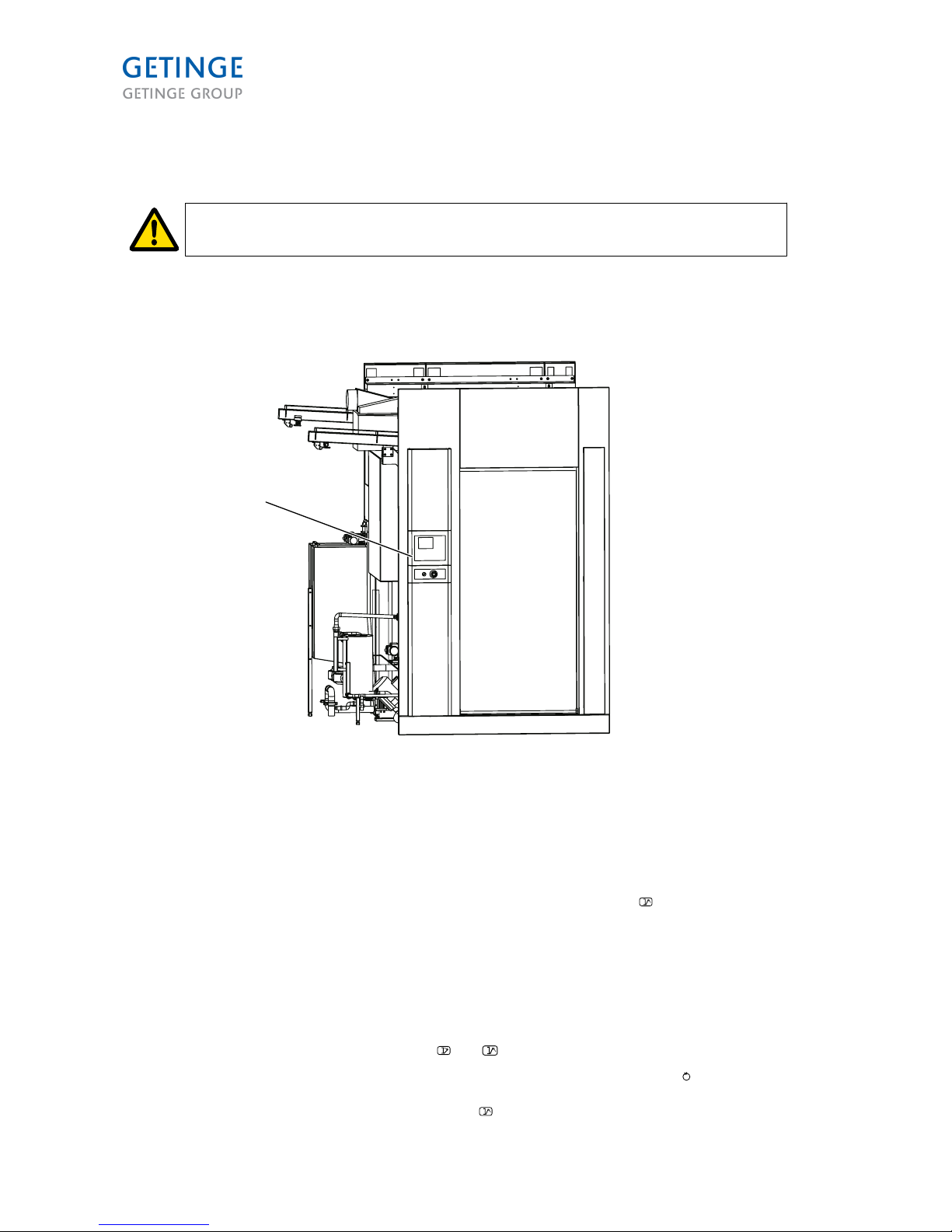
Door operation
The washer-disinfector has one or two doors. Two doors give an ”airlock” function between the soiled
and clean side of the machine. The doors are horizontal sliding doors.
1
001718
1. Control panel
The doors are motorized. As a safety measure, the operator must hold down the open or close button
during the entire opening or closing sequence. If the button is released during the sequence, the door
stops immediately (on a machine with two doors, the door on the clean side can be opened by pressing
the button once).
Machines with two doors have an interlock system so that only one door can be opened at a time. This
means that the door on the clean side must be closed and locked with the button before the door on
the soiled side can be opened.
Where the door meets the floor, there is a threshold which lowers automatically when the door opens and
closes the gap between the chamber floor and the installation floor that is created when the door opens.
This function facilitates loading and unloading of the chamber. When the button is pressed, the closing
sequence is as follows: the threshold comes out, the door closes, the door locks. When the button is
pressed, the opening sequence is as follows: door is unlocked, door opens, the threshold is retracted.
The door must be closed and locked before the start button indicates that the machine is ready. In
standby mode, the door can open and close with and respectively.
When the program is ready, a green lamp comes on, indicating that the process is ready (on both sides
if the machine has two doors). When the items have been unloaded from a machine with two doors, the
door on the clean side must be closed using the button before the door on the soiled side can be
opened.
Page 12 of 166
<Doc_TEC><Doc_6001341502><Rel.A><Lang_en>
Page 13
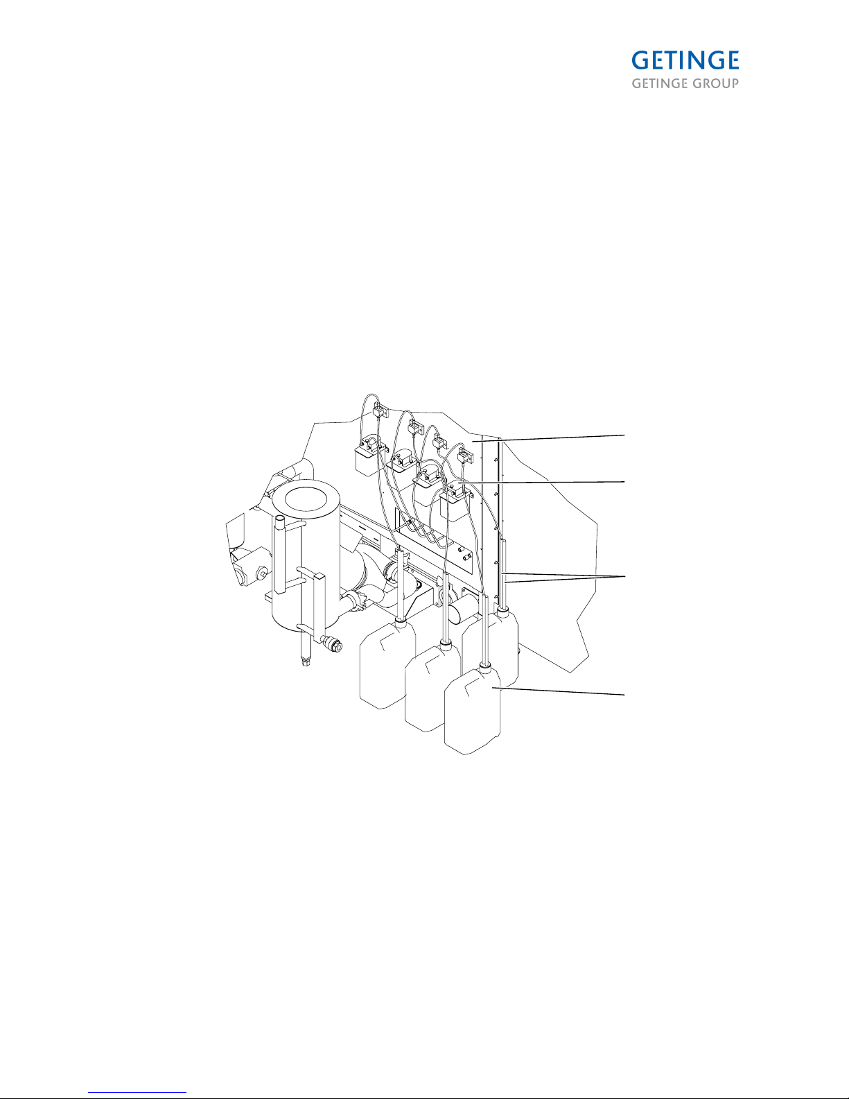
Dosing system
In standard form, the machine has two dosing systems. The dosing amount can be set individually for
each program.
The machine cannot be started if detergent level is to low in one of the detergent holders.
If the detergent bottle is empty, no ready-to-start signal is given. If, with the machine in this mode, the
start button is pressed, the display shows ”DET X LOW LEVEL” (X= 1,2).
You can also install a third or a fourth dosing system.
The machine is equipped with flow monitoring, which is linked to the monitoring system. If the flow of
detergent is too low, this is indicated via an alarm on the display.
4
001719
3
2
1
1. Flowmeter for dosing
2. Dosing pumps
3. Level sensor, detergent
4. Container for detergent/rinsing agent
Page 13 of 166
<Doc_TEC><Doc_6001341502><Rel.A><Lang_en>
Page 14
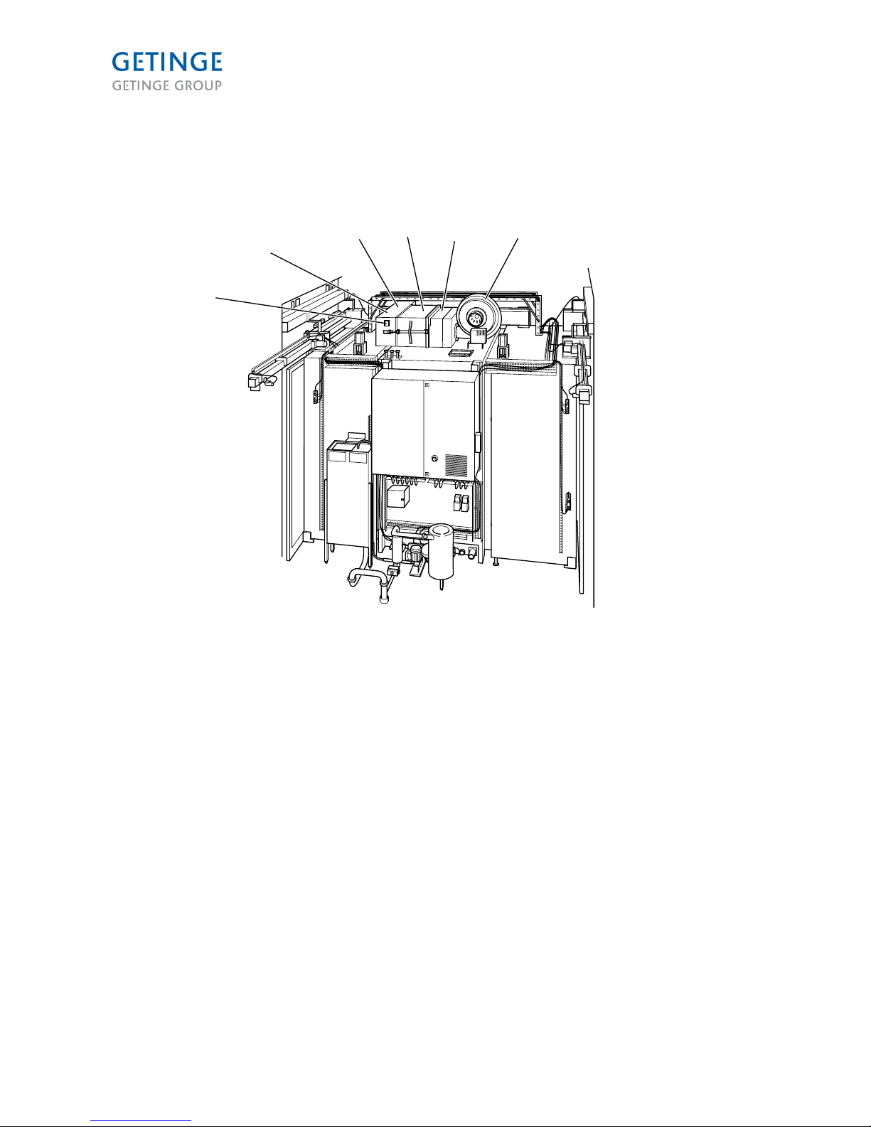
Drying
The machine is fitted by default with a drying system, which includes a fan, heating element, filter, heat
exchanger and air duct, temperature sensor and a pressure differential sensor.
1
2
3 4 5 6
001790
1. Sensor for pressure differential
2. Temperature sensor
3. Air duct
4. Filter
5. Heating element
6. Fan
Page 14 of 166
<Doc_TEC><Doc_6001341502><Rel.A><Lang_en>
Page 15
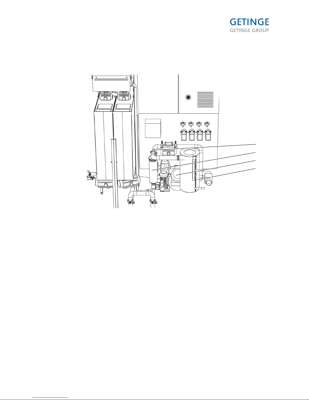
Circulation system
The machine is fitted by default with the following circulation system:
4
1
2
3
1
971
0
00
1. Pressure sensor
2. Filter
3. Circulation Pump
4. Heater
A docking system for docking the wash cart can be added as an option. There are two pressure sensors
in the "monitoring" option, one of which is connected to the main system and one to the monitoring
system.
Page 15 of 166
<Doc_TEC><Doc_6001341502><Rel.A><Lang_en>
Page 16
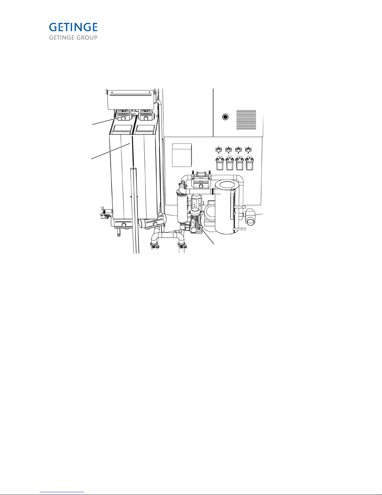
Tanks
The machine is fitted as standard with the following tank system:
1
2
3
001792
1. Waste tank
2. Storage tanks
3. Draining pump
One or two saving tanks can be added as an option. Waste water cooling is also an available option. This
includes a temperature sensor and a valve for cooling water.
Page 16 of 166
<Doc_TEC><Doc_6001341502><Rel.A><Lang_en>
Page 17
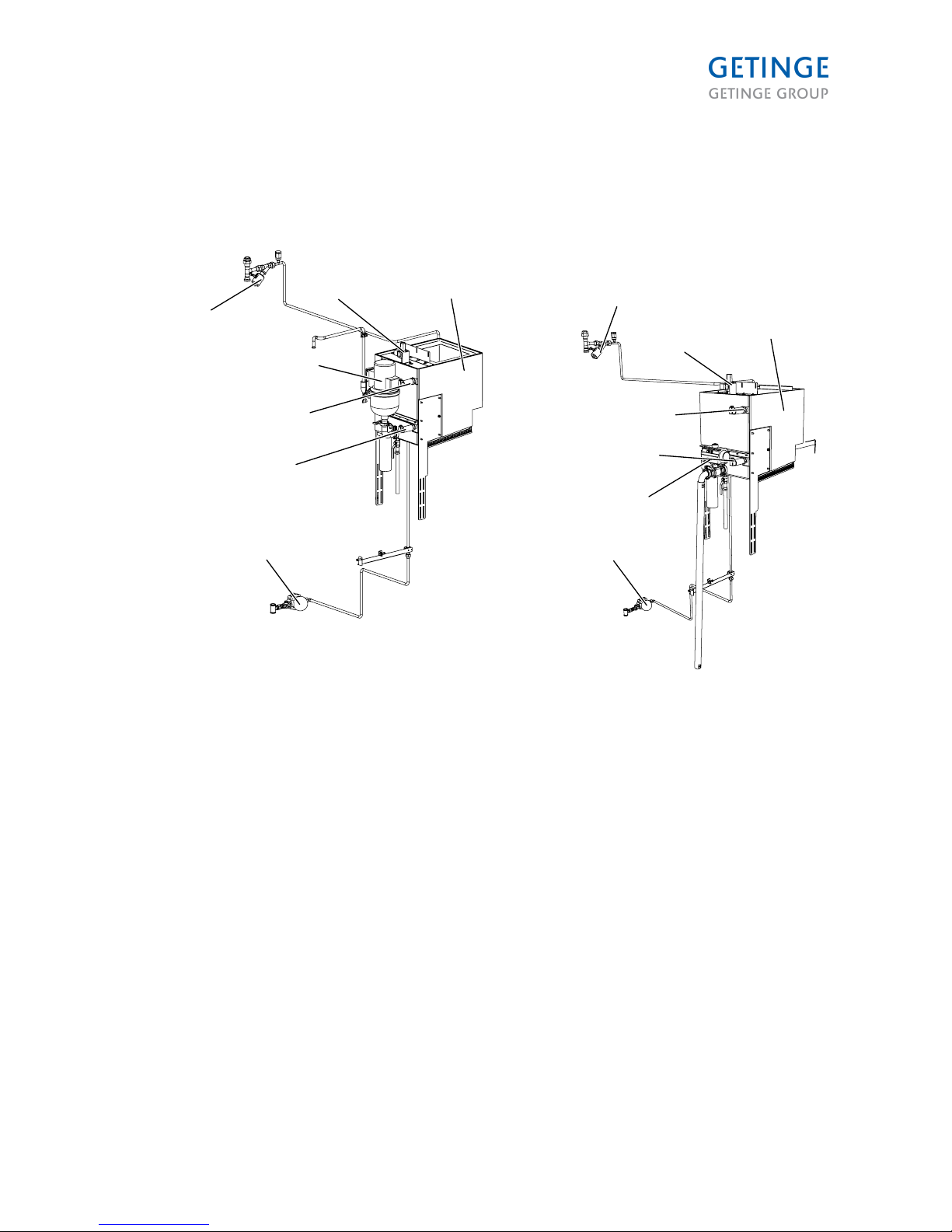
Booster tank
The machine can be equipped with an extra tank for using preheated water in the process.
The following equipment is included:
6
6
1
1
3
3
2
2
5
5
4
7
8
8
001793
1. Steam valve
2. Filling valve
3. Booster tank
4. Auxiliary pump
5. Level switch, high
6. Level switch, low
7. Booster valve
8. Condensate drain
Page 17 of 166
<Doc_TEC><Doc_6001341502><Rel.A><Lang_en>
Page 18
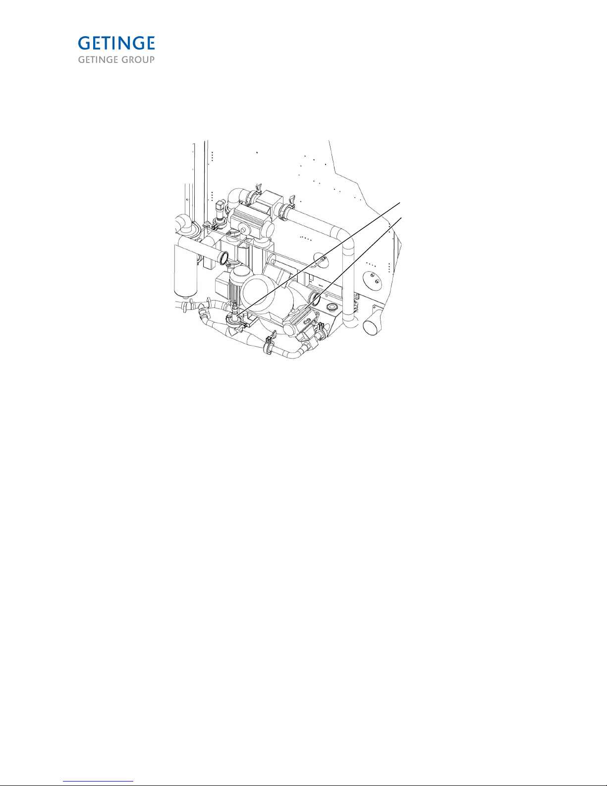
Neutralization system for waste water
The machine can be equipped with a neutralization system for waste water that includes:
2
001794
1
1. pH measuring system
2. Valve
Page 18 of 166
<Doc_TEC><Doc_6001341502><Rel.A><Lang_en>
Page 19
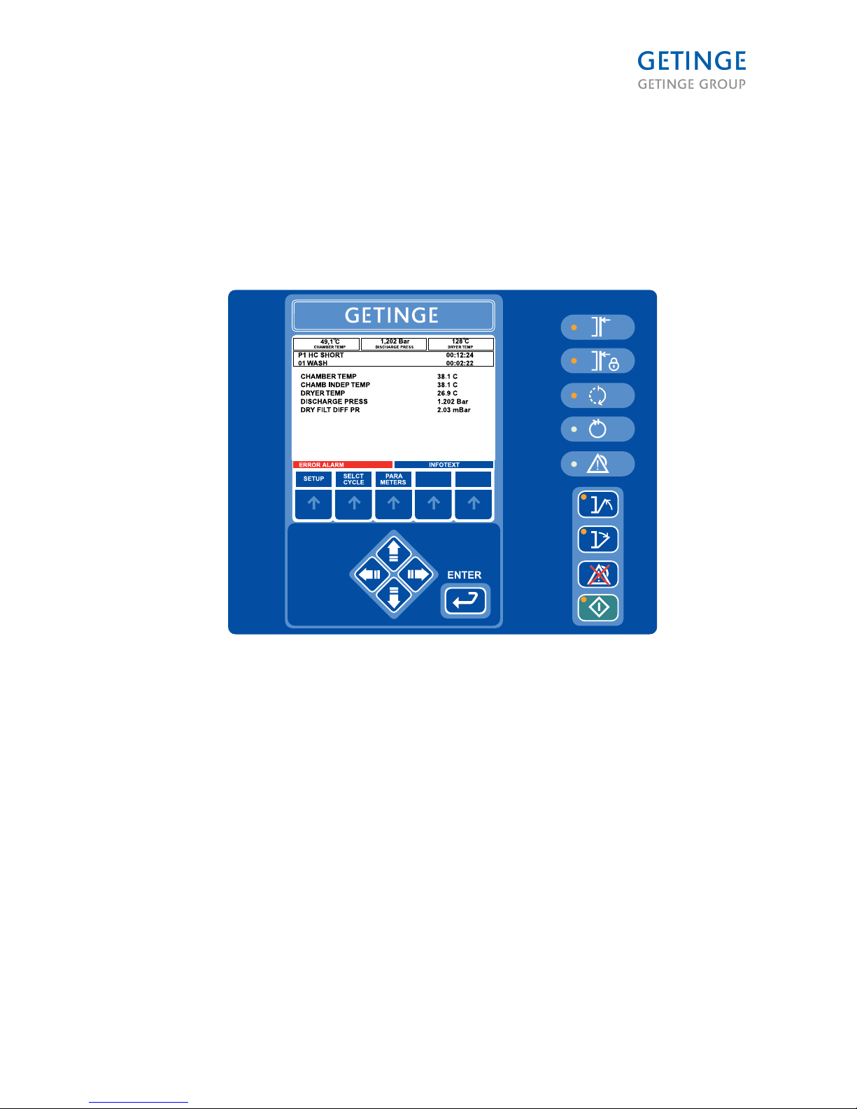
CONTROL PANEL
OP30 panel
Layout
OP30 is a color graphical display with a 320 W x 240 H pixel resolution mounted in a panel with a
number of buttons and LEDs.
000547
Page 19 of 166
<Doc_TEC><Doc_6001341502><Rel.A><Lang_en>
Page 20
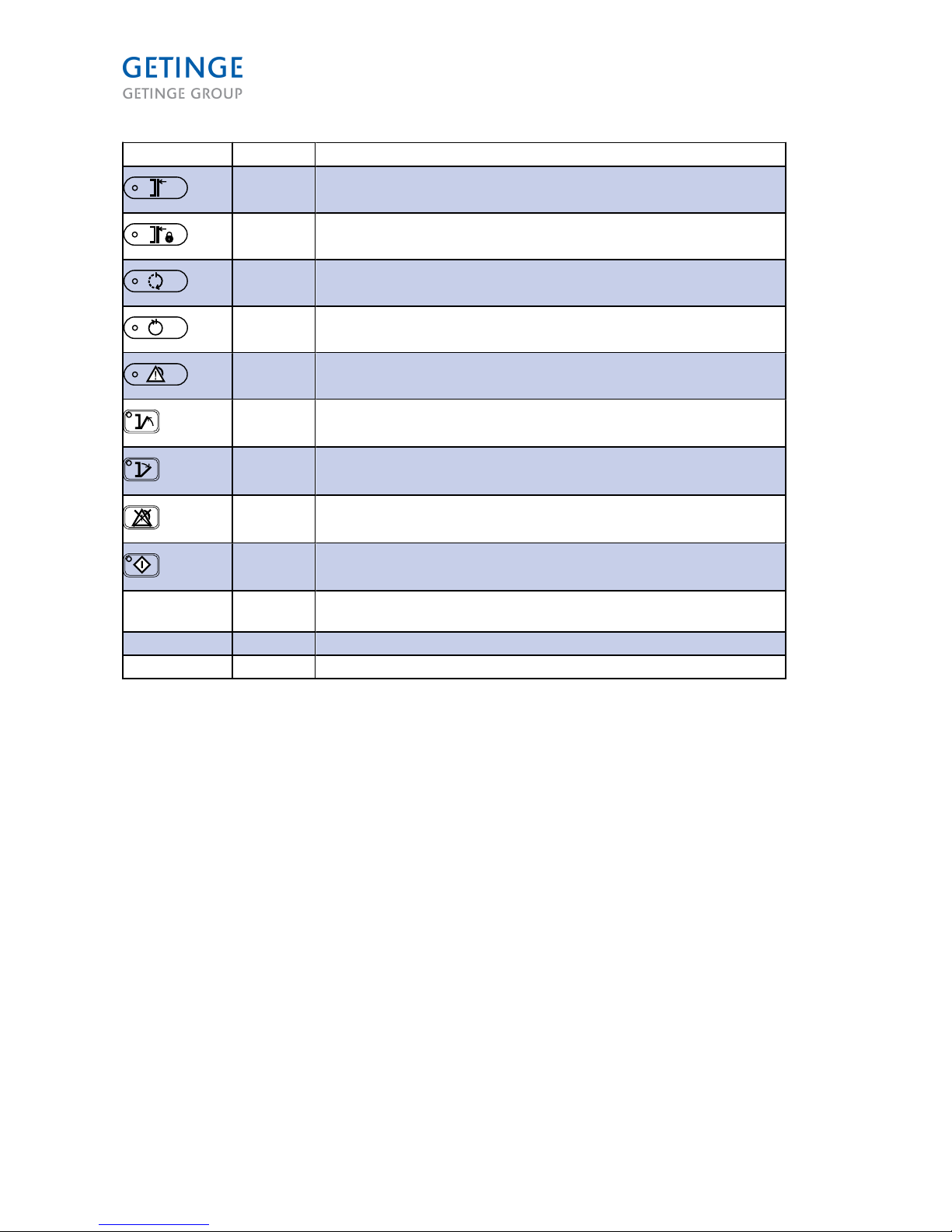
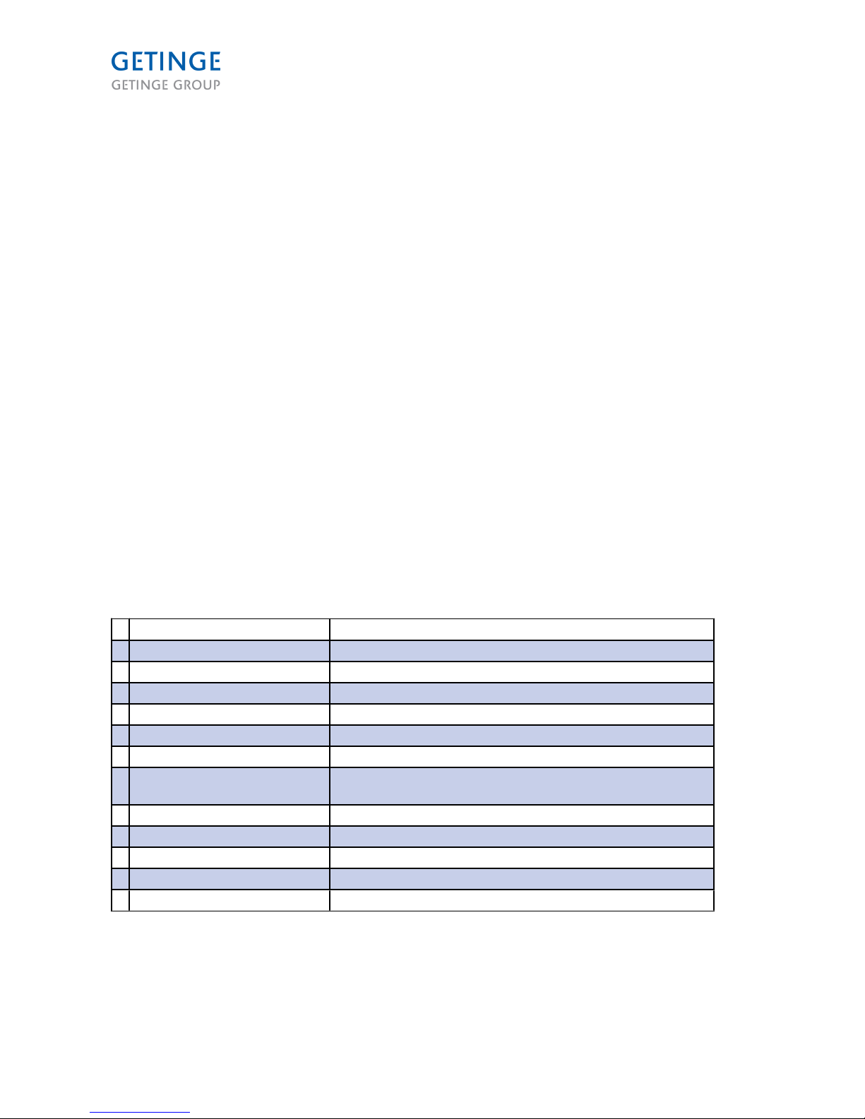
Position Type Explanation
Indication The doors are closed
Indication The doors are closed and locked
Indication Process running
Indication Process completed without errors
Indication Defective process
Button / ind Close door
Button / ind Open door
Key Acknowledge and reset the alarm
Button / ind Cycle start
5 buttons under
the display
Key Function buttons different functions for different displays
4 direction Key Arrow buttons for scrolling up/down in the menus
Enter Key Confirmation
Page 20 of 166
<Doc_TEC><Doc_6001341502><Rel.A><Lang_en>
Page 21
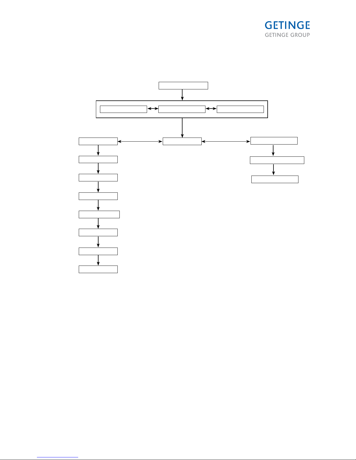
Menu tree
001720
COLDSTART DISPLAY
DETAILS PLOT GRAPH BAR GRAPH
SETUP SELECT CYCLE
DETAILS
PLOT GRAPH
VIEW PARAMTERS
QUICK EDIT PARAMETER*
SYSTEM**
BAR GRAPH
PRINT LAST CYCLE
SELECT PACS
ABOUT
1.1 1.2 1.3
2.1 2.2
2.1.6
2.1.1
2.1.2
2.1.3
2.1.4
2.1.5
2.1.7
2.3.1
EDIT POPUP
2.3.2
2.3
Process display
* Requires principal operator’s password
** Requires service personnel password
Page 21 of 166
<Doc_TEC><Doc_6001341502><Rel.A><Lang_en>
Page 22
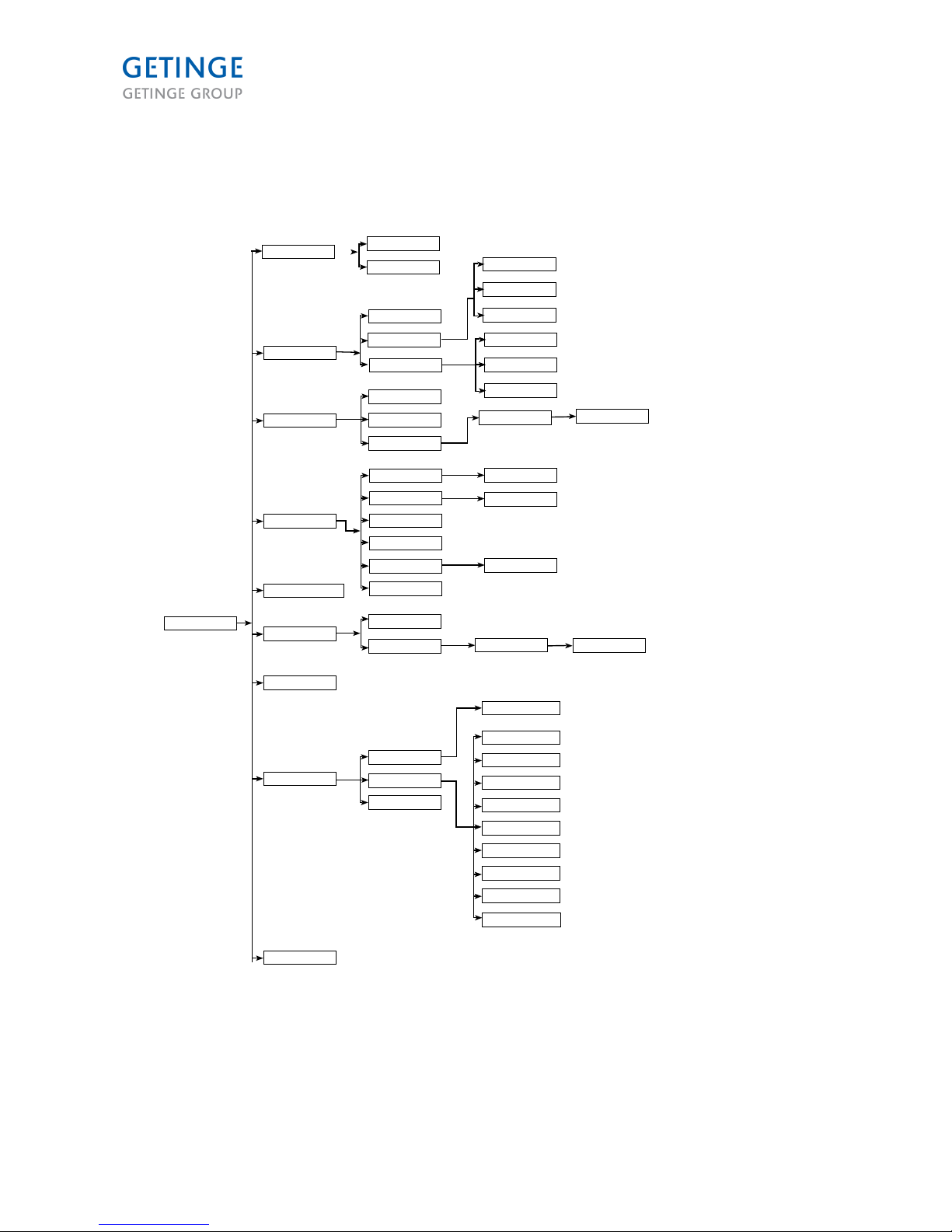
SYSTEM MENU
2.1.6
686000
CALIBRATION
DOCUMENTATION
CONFIGURATION
SYSTEM SETUP
PASSWORDS
DIPSWITCHES
SERVICE
SAVE RAM TO FLASH
EXTE. PARAMETERS
LANGUAGE & DATE UNITS
PANEL SETUP
EDIT CYCLES
PARAMETE R SELECT.
MACHINE NAME
EDIT PARAMETERS
NAME
ADD/DELETE
DIAGNOSTICS
PACS ADDRESS
ERROR LOG
ERROR LOG POPUP
ANALOG OUTPUT
TEST
ANALOG
INPUT
2.1.6.2
AUT. CALIB.
2.1.6.2.2
2.1.6.3
2.1.8.3.1
2.1.8.3.2
2.1.8.3.3
TYPE
2.1.8.3.3.1
2.1.6.4.1.1
2.1.6.4.2
2.1.6.4.2.1
2.1.6.4
2.1.6.4.1
2.1.6.4.3
2.1.6.4.3
2.1.6.4.4
2.1.6.4.5
2.1.6.4.4.1
2.1.6.5
2.1.6.6
2.1.6.6.1
2.1.6.6.2
PASSWORD
2.1.6.6.2.1.1
2.1.6.7
2.1.6.8
2.1.6.8.1
2.1.6.8.1.1
2.1.6.8.2
2.1.6.8.2.1
2.1.6.8.2.2
2.1.6.8.2.3
2.1.6.8.2.4
2.1.6.8.2.5
2.1.6.8.2.6
2.1.6.8.2.7
2.1.6.8.2.8
2.1.6.8.2.9
2.1.6.9
TIME SETTINGS
CALENDER
ALARM CLOCK
2.1.6.1
2.1.6.1.1
2.1.6.1.2
MANUAL CALIBRATION
2.1.6.2.1
DOSE MONITOR SELEC
2.1.6.2.3
FACTOR
2.1.6.2.3.1
2.1.6.2.3.2
2.1.6.2.3.3
MEASURD VOLUME
DESIRED VOLUME
PRINT CYCLE
ITEM
2.1.8.3.3.1.1
ACCESS AREAS
2.1.6.6.2.1
TEST
TEST PRINTER
2.1.6.8.3
2.1.6.2.2.1
2.1.6.2.2.2
2.1.6.2.2.3
HI
LO
PRT
TEST
DIGITAL
INPUT
TEST DIGITAL
OUTPUT
TEST USER FLAG
TEST SYSTEM FLAG
TEST LED AND BUZZER
TEST PULSE COUNTER
MACHINE NAME ENTRY
CYCLE NAME ENTRY
PRINTER
PRINTER LOG VALUES
Page 22 of 166
<Doc_TEC><Doc_6001341502><Rel.A><Lang_en>
Page 23

Display panel rules
Scope
This set of common rules or practices will apply specifically to the LCD display to be used on the OP30. It
is the objective of this section of the user interface to create a common method for selecting and editing
fields, saving data, etc. The goal is to ensure that all screens and functions used on the OP30 panel
operate in a logical and consistent manner. In those cases where there are exceptions to the rules, these
are specific to certain screens and are highlighted with comments on the screen.
General rules
1. The four (4) arrow buttons on the OP30 panel have a repeat function. If you press the button,
the button's function will be repeated 3-5 times per second until the button is released. The
repeat function starts after 0.5-1.0 sec.
2. The ¼ VGA screen will be refreshed 2 times per second.
3. When scrolling in a list, the highlighted field is inverted and displayed in a different color than the
original. The colors are determined by CS.
4. When a character is flashing (during editing), it switches between the normal and inverted
mode.
Softkey buttons
1. There are five (5) program buttons along the bottom of the LCD screen. The buttons use a small
(8x10 pixel) font and have two rows with up to seven (7) characters. The buttons are centered
and have (1) or two (2) pixel buttons in 3D.
2. The buttons are displayed in the same place. For example, if the HOME function is active in a
screen, it will always be displayed in location No. 2.
3. From the main processing screen, which is standard, use the buttons to move to the display
menus and select a function.
Fixed buttons
1. There are five (5) fixed function buttons on the OP30 panel. The fixed buttons are four (4) cursor
direction buttons (up, down, left and right) and the ENTER button.
2. Even if they are not specifically associated with the display being used on the OP30 panel, there
are several fixed buttons for various functions.
Page 23 of 166
<Doc_TEC><Doc_6001341502><Rel.A><Lang_en>
Page 24

Panel operation
1. The display is normally made up of various screens with additional function options, screens
where data can be displayed or screens with adjustable fields where data can be entered or
modified.
2. The arrow buttons can be used to scroll (up, down, right or left) through all of the various
selectable fields on the screen.
3. When you select something by going into a field, the highlighting is inverted to indicate that the
field is selected.
4. If there are more list items than there is room for in the screen, only the first ten items are
displayed along with a scroll bar to the right of the list box.
5. Use the up and down keys to scroll through the list. If the cursor is in the last field in a list, and
there are more fields below, you can go up one (1) row on the screen using the down arrow
button. The same rule applies when going in the opposite direction.
6. All selectable submenus and options work as a circular list, which means that when you press
the down button after highlighting the last item, the cursor moves to the first item in the list. The
circular dropdown list works the same way regardless of how many items there are.
7. The HOME button is always in the number 2 location, and takes you to the main menu and logs
the user out.
8. Scrollable fields may contain a maximum of 120 lines.
9. System messages on the panel, e.g. “System occupied” etc. are displayed in pop-up screens.
Screen modes
A screen has up to three different modes:
1. READ mode – displaying values
2. EDIT mode – editing values
3. SAVE mode – saving values
Page 24 of 166
<Doc_TEC><Doc_6001341502><Rel.A><Lang_en>
Page 25

Field editing
• When the screen is in Read move, the Enter button activates the Edit mode so that you can edit
the highlighted field.
• Use the cursor buttons to edit the field.
• When the button is in Edit mode, the Enter button activates the Save mode.
• Use the cursor buttons to select another field.
• When the screen is in Save mode, the Enter button activates the Edit mode so that you can edit
the highlighted field.
• The SAVE button saves the value in PACS and changes the screen mode to Read.
1. Editing numeric fields - The first character will blink while the remaining are displayed inverted.
You can change the blinking character with the up and down buttons. Press the left or right
arrow buttons to select the next character to the left or right and make it editable. Press the
right arrow button on the character at the far right to move the cursor to the far left. The same
applies for the character on the far left. Once you press ENTER after editing a numeric field, the
system checks to make sure that the value is within the allowable range.
2. Activating field editing - All characters in the field will blink. Press the up or down buttons to
activate the field value for the previous or next field value in the list. If the field is the last value in
the list, you can display the first value in the list by pressing the down button. The same applies
to the first value in the list, if you press the up button.
3. Editing alphanumeric fields – A keyboard appears in a pop-up screen above the active screen.
The pop-up keyboard is not transparent. A cursor displays where the field value is. Field value
will be empty. The first key on the keyboard is highlighted. Use the cursor buttons to move to
the desired character. Press the ENTER button to insert the selected character in the field. Use
the cursor buttons and the ENTER button to enter the remaining characters in the field. The
keyboard supports both upper and lower case characters. Then use the "CAPS LOCK" button
on the keyboard to switch between upper and lower case. Press the OK button to close the
screen and return to the previous screen and insert the selected character in the selected field.
OK and Cancel buttons
Use the OK button in Read mode to go to the previous screen. No dialog box "Confirm cancel"?
The CANCEL function is always in button location 1 and is defined as follows:
a. Read mode – go to previous screen. No dialog box "Confirm cancel"?
b. Edit mode, no pop-up screen – resets the field to the original value and activates Save mode.
Edit mode, pop-up screen – restores the field to its original value, returns to previous screen
and activates Save mode.
c. Save mode – opens "Confirm cancel"? (if activated), resets all fields on the screen to their
original values and returns to the previous screen
1. If the flag in the panel setup menu for confirming SAVE/CANCEL is set to Yes, the "Confirm
save?" question appears when you select SAVE, so that you have to choose YES or NO. Select
YES to continue and save the values in the screen. Select NO to return to the screen.
2. If the flag in the panel setup menu to confirm SAVE/CANCEL is set to Yes, and if any value on
the screen has been modified, the question “Confirm Cancel ?” will be displayed when you
push CANCEL, allowing the user to select YES or NO. YES will continue and cancel. Select NO
to return to the screen.
Page 25 of 166
<Doc_TEC><Doc_6001341502><Rel.A><Lang_en>
Page 26
Panel communication
Panel boot sequence
1. When the control panel starts, the previous PACS system (saved in the control panel's memory)
is connected.
2. Try the next PACS address in the list, if a connection cannot be established (saved in the
control panel's memory).
3. If it is not possible to establish a connection with any of the defined PACS addresses in the list
or if there isn't a list (new panel), you will need to search through all addresses (01-99) until a
connection is established. Stop searching when the first address is found. Add the new PACS
address to the list.
4. When the connection is established with a different PACS than the previous one, go to the
menu "Select PACS" (2.1.5) and select the PACS that was found.
5. The default settings for the panel are saved in the PACS RAM memory and downloaded to the
panel during startup. Default settings are programmed with CS 1000.
Communication error
If a communications error occurs, a message will be displayed on the screen, “COMMUNICATION
ERROR”, while the panel will try to establish a communication with the PACS. The panel will try
communicating with PACS until the connection can be established.
User access and passwords
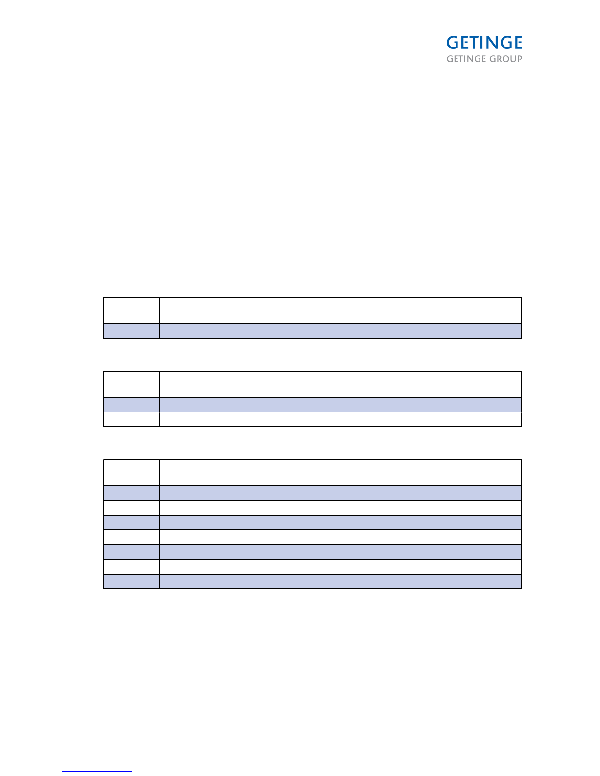
Access areas
The menu tree on OP30 is divided into several access areas. Each area is allowing access to various
screens. The areas are:
Access area:
Access rights to:
A Parameter Settings Parameter screen (2.3) and all submenus
B Time Settings Time settings (2.1.6.1) and all submenus
C Calibration Calibration screen (2.1.6.2) and all submenus
D Boolean Password 1 Used for Boolean password, initiated from Boolean code
E Service Service screen (2.1.6.8) and all submenus.
F DIP switch The DIP switch screen (2.1.6.7) and all submenus
G Non Process Critical
Configuration
Configuration screen (2.1.6.4) and all sub-screens
The Save RAM to Flash screen (2.1.6.9) and all submenus
H Process Critical Configuration System settings screen (2.1.6.5)
I Boolean Code Does not apply to this panel
J Password Setup Password screen (2.1.6.6) and all submenus
K Document Document screen (2.1.6.3) and all submenus
L Boolean Password 2 Used for Boolean password, initiated from Boolean code
After accessing the system menu (2.1.6) and entering the password, the user will only see sub-menus to
(2.1.6) that the user has access to. Other menus will be hidden. When logged in the user can freely move
around in the menu tree. However leaving the system menu by using CANCEL or HOME will log out user.
Next time user tries to access the system menu, the password question will show again. If a user tries to
access an area that does not belong to the users access rights, a message “No Access” will be
displayed.
Page 26 of 166
<Doc_TEC><Doc_6001341502><Rel.A><Lang_en>
Page 27
Password system in the standard 9100-Series machine of Getinge Disinfection AB
Password
Users are defined in screen (2.1.6.6). In screen (2.1.6.6.1) users will be entered with a name, a password
and areas the user has access to (A through L). Passwords may be numerical or alphanumerical. The
password must have a minimum of 3 characters and a maximum of 6 characters. Upper case or lower
case letters do not matter.
Different users may not have the same password. This shall be checked when entering a new password.
The authorization groups are as following:
• Operator (no password requested for start).
• Main operator
• Supervisor
• Service
Operator
Access
code:
Access rights to:
- No authorization to access areas A through L
Main operator
Access
code:
Access rights to:
A Authorization to modify the program, adjustable parameters (A parameters).
D Authorization to acknowledge alarms and start password protected programs.
Supervisor
Access
code:
Access rights to:
A Authorization to modify the program, adjustable parameters (A parameters).
B Authorization to modify time settings
C Authorization to use calibration function.
D Authorization to acknowledge alarms and start password protected programs.
G Authorization to modify the non-process-critical configuration, extended parameters
J Authorization to define new users and change passwords.
K Authorization to the documentation system.
Page 27 of 166
<Doc_TEC><Doc_6001341502><Rel.A><Lang_en>
Page 28
Service
Access
code:
Access rights to:
A Authorization to modify the program, adjustable parameters (A parameters).
B Authorization to modify time settings
C Authorization to use calibration function.
D Authorization to acknowledge alarms and start password protected programs.
E Authorization to service menu.
F Authorization to change dipswitches.
G Authorization to modify the non-process-critical configuration, extended parameters
H Authorization to modify the process-critical configuration, system setup.
I Authorization to change Boolean codes.
J Authorization to define new users and change passwords.
K Authorization to the documentation system.
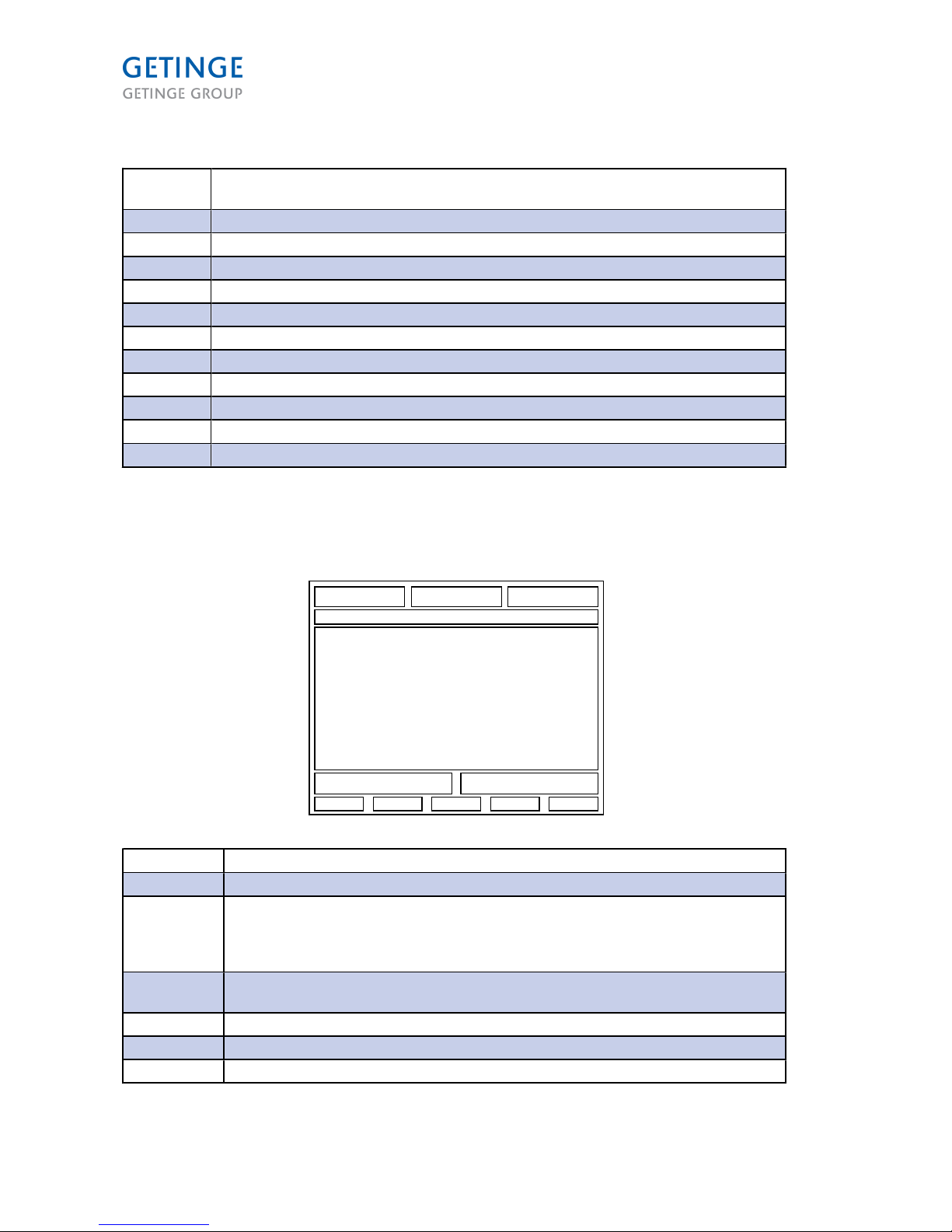
Screen Layout
Button:
1 2 3
4
5
6 7
8 9 10 11 12
000555
Section
Description
Section 1-3: Process value or Parameter value
Section 4: Cycle number and name + Phase name and sub number
This field is also linked to the Process Ready LED in terms of colors. If the process is
normal with no errors, a green light appears. If errors it is displayed red. If a test process,
it blinks with the same function as above.
Section 5: Main screen for text values, bar graphs, trend curves, parameter input data, test
functions, messages, system messages, etc.
Section 6: Alarm messages (tripping)
Section 7: Information and system messages (Non-critical)
Section 8-12: Softkey buttons
Page 28 of 166
<Doc_TEC><Doc_6001341502><Rel.A><Lang_en>
Page 29

Colors:
000556
1 2 3
4
5
6 7
8 9 10 11 12
Section 4 If the phase is in progress, the area showing the current phase, is displayed in light blue.
• If there is an alarm when a normal sterilization process is running, the area is displayed in red. *
• If there is an alarm when a test process is running, the area will blink in red. *
• After normal sterilization process is completed, the area is displayed in green. *
• After a test process is completed, the area is blinking in green. *
* Those functions are linked to the LEDs on the panel and can be programmed with the application
software.
Button description
The following buttons/keys are panel controlled:
• 5 program buttons
• 4 cursor buttons
• 1 ENTER button
Following buttons/keys are program-controlled:
• 1 acknowledge alarm key
• 1 door open
• 1 door close
• 1 start
LED description
Following LEDs are program-controlled:
• Start Available
• Door(s) Closed
• Door(s) Locked
• In Progress
• Process Error
• Process Complete
• Door Open Available
• Door Close Available
Page 29 of 166
<Doc_TEC><Doc_6001341502><Rel.A><Lang_en>
Page 30

Buzzer
The buzzer in the control panel is program-controlled.
Cold Start Screen (0.1)
This screen is displayed when the OP30 panel is cold started. It will show while the panel boots up and
starts up communication with the PACS, before the Main Process Screen comes on. As this screen is
showing, all LEDs on the panel will be lit for test.
PACS 3500
000546
Panel screen
Process screen
When the washer-disinfector has started up, the Cold Start Screen is replaced by either screen 1.1, 1.2
or 1.3. If no active selection is made, screen 1.1 appears after start-up.
Screens (1.1), (1.2) and (1.3) display the values for the process.
These screens contain the "MENU", "SELECT PROGRAM" and "EDIT VALUES" buttons, which brings up
other screens.
Page 30 of 166
<Doc_TEC><Doc_6001341502><Rel.A><Lang_en>
Page 31

Details (1.1)
49,1 C
WASH1 TEMP SP
P1 HC SHORT
00:12:24
01 STANDBY
00:02:22
A34 I/O FAULT
00:03:00
WASH1 TIME
128,1 C
DRYER TEMP
SETUP
SELECT
CYCLE
PARA-
METERS
CHAMBER TEMP
17,2 C
INDEPENDENT TEMP
38,1 C
DISCHARGE PRESS
0.000 BAR
DRYER TEMP
22,6 C
DRY FILTER DIFF PR
BOOSTER TEMP
2,03 mBar
21,3 C
1
32
11
7
12
13
6
5
4
8
9
10
14
15
1. WASH1 TEMP SP
2. WASH1 TIME
3. DRYER TEMP
4. PARAMETERS
5. SELECT CYCLE
6. SETUP
7. A34 I/O FAULT
8. BOOSTER TEMP
9. DRY FILTER DIFF PR
10. DRYER TEMP
11. DISCHARGE PRESS
12. INDEPENDENT TEMP
13. CHAMBER TEMP
14. STANDBY
15. HC SHORT
Page 31 of 166
<Doc_TEC><Doc_6001341502><Rel.A><Lang_en>
Page 32

Plotgraph (1.2)
49,1 C
WASH1 TEMP SP
P1 HC SHORT 00:12:24
01 STANDBY 00:02:22
A34 I/O FAULT
00:03:00
WASH1 TIME
128,1 C
DRYER TEMP
SET UP
SELECT
CYCLE
PARA-
METERS
DISCHARGE PRESS
WASH1 TEMP SP
BAR
C
000714
1
32
8
7
9
10
6
5
4
11
12
1. WASH1 TEMP SP.
2. WASH1 TIME
3. DRYER TEMP
4. PARAMETERS
5. SELECT CYCLE
6. SETUP
7. A34 I/O FAULT
8. GRAPH
9. WASH1 TEMP SP
10. DISCHARGE PRESS
11. STANDBY
12. HC SHORT
Page 32 of 166
<Doc_TEC><Doc_6001341502><Rel.A><Lang_en>
Page 33

Bar graph (1.3)
49,1 C
WASH1 TEMP SP
P1 HC SHORT 00:12:24
01 STANDBY 00:02:22
A34 I/O FAULT
00:03:00
WASH1 TIME
128,1 C
DRYER TEMP
SET UP
PARA-
METERS
CHAMBER TEMP
DISCHARGE PRESS
38,1 °C 0.000 BAR
00:19
TIME REMAINING
000715
SELECT
CYCLE
1
32
9
10
8
7
6
11
12
4
5
1. WASH1 TEMP SP
2. WASH1 TIME
3. DRYER TEMP
4. DISCHARGE PRESS
5. TIME REMAINING
6. PARAMETERS
7. SELECT CYCLE
8. SETUP
9. A34 I/O FAULT
10. CHAMBER TEMP
11. STANDBY
12. HC SHORT
Page 33 of 166
<Doc_TEC><Doc_6001341502><Rel.A><Lang_en>
Page 34

Menus (2.1)
49,1 C
WASH1 TEMP SP
P1 HC SHORT 00:12:24
01 STANDBY 00:02:22
A34 I/O FAULT
00:03:00
WASH1 TIME
128,1 C
DRYER TEMP
CANCEL
DETAILS
PLOTGRAPH
BAR GRAPH
SYSTEM MENU
ABOUT
317
000
17.2 C
17.6 C
0.000 BAR
22.6 C
0.06 mBAR
21.3 C
PRINT LAST CYCLE
SELECT PACS
7
2
8
9
1
3
4
5
6
1. CANCEL
2. A34 I/O FAULT
3. ABOUT
4. SYSTEM MENU
5. SELECT PACS
6. PRINT LAST CYCLE
7. BAR GRAPH
8. PLOTGRAPH
9. DETAILS
Menus of popup list boxes. A scroll list is displayed if there are more selections available than
what is visible. The previous screen can still be seen behind the list.
CANCEL opens the Main Process Screen
DETAILS make screen (1.1) into the Main Process Screen.
PLOT GRAPH makes screen (1.2) into the Main Process Screen.
BAR GRAPH makes screen (1.3) into the Main Process Screen.
PRINT LAST CYCLE is only available during set-up
SELECT PACS is only displayed if the system has more than one PACS.
SYSTEM MENU requires a password to modify settings in PACS.
DEVICE INFO opens the device info screen.
Page 34 of 166
<Doc_TEC><Doc_6001341502><Rel.A><Lang_en>
Page 35

Details (2.1.1)
DETAILS is selected by highlighting the text in the display using the cursor buttons. When the DETAILS
text is highlighted, press ENTER. When DETAILS is selected, screen (1.1) becomes the process screen
while you go up one level in the menu tree and end up in the process screen.
49,1 C
WASH1 TEMP SP
P1 HC SHORT
00:12:24
01 STANDBY
00:02:22
A34 I/O FAULT
00:03:00
WASH1 TIME
128,1 C
DRYER TEMP
SETUP
SELECT
CYCLE
PARA-
METERS
CHAMBER TEMP
17,2 C
INDEPENDENT TEMP
38,1 C
DISCHARGE PRESS
0.000 BAR
DRYER TEMP
22,6 C
DRY FILTER DIFF PR
BOOSTER TEMP
2,03 mBar
21,3 C
1
32
11
7
12
13
6
5
4
8
9
10
14
15
1. WASH1 TEMP SP
2. WASH1 TIME
3. DRYER TEMP
4. PARAMETERS
5. SELECT CYCLE
6. SETUP
7. A34 I/O FAULT
8. BOOSTER TEMP.
9. DRY FILTER DIFF PR
10. DRYER TEMP
11. DISCHARGE PRESS
12. INDEPENDENT TEMP
13. CHAMBER TEMP
14. STANDBY
15. HC SHORT
Page 35 of 166
<Doc_TEC><Doc_6001341502><Rel.A><Lang_en>
Page 36

Plotgraph (2.1.2)
When PLOT GRAPH is selected, the screen (1.2) becomes the process screen, while you go up one level
in the menu tree and end up in the process screen.
49,1 C
WASH1 TEMP SP
P1 HC SHORT 00:12:24
01 STANDBY 00:02:22
A34 I/O FAULT
00:03:00
WASH1 TIME
128,1 C
DRYER TEMP
SET UP
SELECT
CYCLE
PARA-
METERS
DISCHARGE PRESS
WASH1 TEMP SP
BAR
C
000714
1
32
8
7
9
10
6
5
4
11
12
1. WASH1 TEMP SP.
2. WASH1 TIME
3. DRYER TEMP
4. PARAMETERS
5. SELECT CYCLE
6. SETUP
7. A34 I/O FAULT
8. GRAPH
9. WASH1 TEMP SP
10. DISCHARGE PRESS
11. STANDBY
12. HC SHORT
Page 36 of 166
<Doc_TEC><Doc_6001341502><Rel.A><Lang_en>
Page 37

Bar graph (2.1.3)
When BAR GRAPH is selected, screen (1.3) becomes the process screen, while you go up one level in
the menu tree and end up in the process screen.
49,1 C
WASH1 TEMP SP
P1 HC SHORT 00:12:24
01 STANDBY 00:02:22
A34 I/O FAULT
00:03:00
WASH1 TIME
128,1 C
DRYER TEMP
SET UP
PARA-
METERS
CHAMBER TEMP
DISCHARGE PRESS
38,1 °C 0.000 BAR
00:19
TIME REMAINING
000715
SELECT
CYCLE
1
32
9
10
8
7
6
11
12
4
5
1. WASH1 TEMP SP
2. WASH1 TIME
3. DRYER TEMP
4. DISCHARGE PRESS
5. TIME REMAINING
6. PARAMETERS
7. SELECT CYCLE
8. SETUP
9. A34 I/O FAULT
10. CHAMBER TEMP
11. STANDBY
12. HC SHORT
Page 37 of 166
<Doc_TEC><Doc_6001341502><Rel.A><Lang_en>
Page 38

Print last cycle menu (2.1.4)
49,1 C
WASH1 TEMP SP
P1 HC SHORT 00:12:24
01 STANDBY 00:02:22
A34 I/O FAULT
00:03:00
WASH1 TIME
128,1 C
DRYER TEMP
CANCEL
PLOTGRAPH
BAR GRAPH
SYSTEM MENU
SELECT PACS
ABOUT
000716
DETAILS
17.2 C
17.6 C
0.000 BAR
22.6 C
0.06 mBAR
21.3 C
PRINT LAST CYCLE
1
2
1. CANCEL
2. PRINT LAST CYCLE
PRINT LAST CYCLE is only shown in standby mode.
The menu item brings you to the CONFIRM PRINT screen (2.1.4.1).
CANCEL returns to default screen.
Page 38 of 166
<Doc_TEC><Doc_6001341502><Rel.A><Lang_en>
Page 39

Confirm Print last cycle (2.1.4.1)
49,1 C
WASH1 TEMP SP
P1 HC SHORT 00:12:24
01 STANDBY 00:02:22
A34 I/O FAULT
00:03:00
WASH1 TIME
128,1 C
DRYER TEMP
CANCEL
HOME NO
YES
PRINT LAST CYCLE
000717
3
2
1
4
5
1. YES
2. NO
3. HOME
4. CANCEL
5. PRINT LAST CYCLE
CANCEL reverts to the process screen.
NO opens the previous screen (2.1.4)
YES prints last cycle and opens previous menu (2.1.4)
Page 39 of 166
<Doc_TEC><Doc_6001341502><Rel.A><Lang_en>
Page 40

Select PACS (2.1.5)
49,1 C
WASH1 TEMP SP
P1 HC SHORT 00:12:24
01 STANDBY 00:02:22
A34 I/O FAULT
00:03:00
WASH1 TIME
128,1 C
DRYER TEMP
CANCEL
WASHER
SUPERVISOR
000718
2
3
1
1. CANCEL
2. WASHER
3. SELECT PACS
CANCEL reverts to default process screen.
ENTER button saves the PACS ID in the panel memory and start communication to the selected PACS.
The screen closes and returns to default process screen.
Page 40 of 166
<Doc_TEC><Doc_6001341502><Rel.A><Lang_en>
Page 41

System menu (2.1.6)
49,1 C
WASH1 TEMP SP
P1 HC SHORT 00:12:24
01 STANDBY 00:02:22
A34 I/O FAULT
00:03:00
WASH1 TIME
128,1 C
DRYER TEMP
ENTER PASSWORD
PASSWORD:
CANCEL DELETE OK
A
K
U
!
.
2
B
L
V
”
:
3
C
M
W
#
+
4
D
N
X
%
SPACE
5
E
O
Y
&
6
F
P
Z
(
7
G
Q
Å
)
8
H
R
Ä
\
-
9
I
S
Ö
,
/
0
J
T
Ü
;
=
000719
1
4
3
2
1
1. OK
2. DELETE
3. CANCEL
4. PASSWORD
DELETE removes the last character in the string. Entering the correct password and pushing OK moves
to SYSTEM MENU (2.1.6).
Page 41 of 166
<Doc_TEC><Doc_6001341502><Rel.A><Lang_en>
Page 42

TIME REMAINING
DISCHARGE PRESS
0.000 BAR
49,1 C
WASH1 TEMP SP
P1 HC SHORT 00:12:24
01 STANDBY 00:02:22
A34 I/O FAULT
00:03:00
WASH1 TIME
128,1 C
DRYER TEMP
CANCEL
HOME
000720
PLOTGRAPH
BAR GRAPH
ABOUT
DETAILS
SYSTEM MENU
TIME SETTINGS
CALIBRATION
DOCUMENTATION
CONFIGURATION
SYSTEM SETUP
PASSWORD
1
2
1. CANCEL
2. TIME SETTINGS
CANCEL returns to the menu screen (2.1). The system menu is a series of pop-up list boxes. If more
selections are available than are visible then a scroll bar should indicate this.
Page 42 of 166
<Doc_TEC><Doc_6001341502><Rel.A><Lang_en>
Page 43

Time settings (2.1.6.1)
TIME REMAINING
0.000 BAR
49,1 C
WASH1 TEMP SP
P1 HC SHORT 00:12:24
01 STANDBY 00:02:22
A34 I/O FAULT
00:03:00
WASH1 TIME
128,1 C
DRYER TEMP
CANCEL
HOME
000721
PLOTGRAPH
BARGRAPH
ABOUT
DETALS
SYSTEM MENU
TIME SETTING
CALIBRATION
DOCUMENTATION
CONFIGURATION
SYSTEM SETUP
PASSWORD
CALENDAR
ALARM CLOCK
DISCHARGE PRESS
3
1
2
1. SYSTEM MENU
2. TIME SETTINGS
3. CALENDAR
Page 43 of 166
<Doc_TEC><Doc_6001341502><Rel.A><Lang_en>
Page 44

Calendar (2.1.6.1.1)
49,1 C
WASH1 TEMP SP
P1 HC SHORT 00:12:24
01 STANDBY 00:02:22
A34 I/O FAULT
00:03:00
WASH1 TIME
128,1 C
DRYER TEMP
CANCEL HOME OK
002629
CALENDAR
TIME 11:36:34 HH:MM:SS
DATE 2013/12/17 YYYY/MM/DD
4
2 1
3
1. OK
2. CANCEL
3. DATE
4. TIME
Select the value to be changed using the button arrows and confirm with ENTER. When a value is
selected, the screen will be displayed in SAVE mode. Modify the time and date using the arrow buttons.
Confirm with the SAVE button when the time and date are correct. When the values are confirmed, the
Time settings screen reappears (2.1.6.1).
Page 44 of 166
<Doc_TEC><Doc_6001341502><Rel.A><Lang_en>
Page 45

Alarm clock (2.1.6.1.2)
49,1 C
WASH1 TEMP SP
P1 HC SHORT 00:12:24
01 STANDBY 00:02:22
A34 I/O FAULT
00:03:00
WASH1 TIME
128,1 C
DRYER TEMP
CANCEL
HOME
OK
ALARM CLOCK
(HH:M) MTOTFLS
000722
1
3
2
1. WEEKDAYS
2. A SYMBOL DISPLAYS HERE IF THERE IS AN ACTIVE ALARM
3. TIME
When there is an alarm clock in the system, the time appears in the field under (HH:MM) and the
weekdays when the alarm clock is active are MTWTFSS. If the alarm is active on Mondays, a 1 is
displayed under the M, if the alarm is inactive, a 0 is displayed.
Page 45 of 166
<Doc_TEC><Doc_6001341502><Rel.A><Lang_en>
Page 46

Calibration (2.1.6.2)
TIME REMAINING
DISCHARGE PRESS
0.000 BAR
49,1 C
WASH1 TEMP SP
P1 HC SHORT 00:12:24
01 STANDBY 00:02:22
A34 I/O FAULT
00:03:00
WASH1 TIME
128,1 C
DRYER TEMP
CANCEL
HOME
000723
PLOTGRAPH
BAR GRAPH
ABOUT
DETAILS
SYSTEM MENU
TIME SETTINGS
CALIBRATION
DOCUMENTATION
CONFIGURATION
SYSTEM SETUP
PASSWORD
MANUAL
AUTOMATIC
DOSE MONITOR
3
2
1
1. HOME
2. CANCEL
3. MANUAL
Page 46 of 166
<Doc_TEC><Doc_6001341502><Rel.A><Lang_en>
Page 47

Manual calibration (2.1.6.2.1)
49,1 C
WASH1 TEMP SP
P1 HC SHORT 00:12:24
01 STANDBY 00:02:22
A34 I/O FAULT
00:03:00
WASH1 TIME
128,1 C
DRYER TEMP
CANCEL
OK
MANUAL CALIBRATION
SENSOR GAIN OFFSET VALUE
00 CHAMBER TEMP 1,000 0,0 49,1
01 DRYER TEMP 1,000 0,0 128,0
02 DRAIN TEMP 1,000 0,0 9,999
03 BOOSTER TEMP 1,000 0,0 1,205
05 DISCHARGE PRESS 1,000 0,0 43,1
06 CONDUCTIVITY FR 1,000 0,0 9,999
000724
1
1. VALUE
The "Value" field cannot be edited. It displays the current sensor value.
The PRINT button is displayed in standby mode and prints a list of all specified sensors.
Page 47 of 166
<Doc_TEC><Doc_6001341502><Rel.A><Lang_en>
Page 48

Automatic calibration (2.1.6.2.2)
49,1 C
WASH1 TEMP SP
P1 HC SHORT 00:12:24
01 STANDBY 00:02:22
A34 I/O FAULT
00:03:00
WASH1 TIME
128,1 C
DRYER TEMP
CANCEL
AUTOMATIC CALIBRATION
SENSOR CALIBRATE
00 CHAMBER TEMP YES
01 DRYER TEMP NO
02 DRAIN TEMP NO
03 BOOSTER TEMP NO
05 DISCHARGE PRESS NO
06 CONDUCTIVITY FR NO
000725
2
1
1. CALIBRATE YES/NO
2. CANCEL
Default value is NO. When any sensor is set to YES and this is confirmed with ENTER, the NEXT button
appears in the bottom right corner. NEXT opens the AUTOMATIC CALIBRATION HIGH/LOW (2.1.8.2.2.2)
screen.
If a sensor is set to YES, the other sensors change color and cannot be selected.
Page 48 of 166
<Doc_TEC><Doc_6001341502><Rel.A><Lang_en>
Page 49

Automatic calibration setting low (2.1.6.2.2.1)
49,1 C
WASH1 TEMP SP
P1 HC SHORT 00:12:24
01 STANDBY 00:02:22
A34 I/O FAULT
00:03:00
WASH1 TIME
128,1 C
DRYER TEMP
CANCEL
LOW
SAVE
SCROLL
UP
SCROLL
DOWN
+/-
AUTOMATIC CALIBRATION
SENSOR GAIN OFFSET VALUE
00 CHAMBER TEMP 1,000 0,0 49,1
LOW REF 0.0 HIGH REF 0.0
000726
1
1. LOW SAVE
The LOW SAVE button is used to confirm low reference value and to open screen (2.1.6.2.2.2).
Page 49 of 166
<Doc_TEC><Doc_6001341502><Rel.A><Lang_en>
Page 50

Automatic calibration setting Hi (2.1.6.2.2.2)
49,1 C
WASH1 TEMP SP
P1 HC SHORT 00:12:24
01 STANDBY 00:02:22
A34 I/O FAULT
00:03:00
WASH1 TIME
128,1 C
DRYER TEMP
CANCEL
HIGH
SAVE
SCROLL
UP
SCROLL
DOWN
+/-
AUTOMATIC CALIBRATION
SENSOR GAIN OFFSET VALUE
00 CHAMBER TEMP 1,000 0,0 49,1
LOW REF 0.0 HIGH REF 0.0
000727
2
1
3
1. HIGH REF
2. HIGH SAVE
3. CANCEL
CANCEL opens the Select automatic sensor calibration (2.1.6.2.2).
Use the HIGH SAVE button to confirm the reference HIGH and open the screen where a calibration
protocol can be printed (2.1.6.2.2.3).
The values for increasing and compensation as recalculated.
Page 50 of 166
<Doc_TEC><Doc_6001341502><Rel.A><Lang_en>
Page 51

Automatic calibration setting print calibration protocol (2.1.6.2.2.3)
49,1 C
WASH1 TEMP SP
P1 HC SHORT 00:12:24
01 STANDBY 00:02:22
A34 I/O FAULT
00:03:00
WASH1 TIME
128,1 C
DRYER TEMP
YES
NO
AUTOMATIC CALIBRATION
PRINT CALIBRATION PROTOCOL?
000728
2
1
1. NO
2. YES
NO opens the CALIBRATION menu (2.1.8.2)
YES prints calibration protocol using the logged in name as signature and opens CALIBRATION (2.1.8.2).
Page 51 of 166
<Doc_TEC><Doc_6001341502><Rel.A><Lang_en>
Page 52

Dose monitor calibration (2.1.6.2.3)
49,1 C
WASH1 TEMP SP
P1 HC SHORT 00:12:24
01 STANDBY 00:02:22
A34 I/O FAULT
00:03:00
WASH1 TIME
128,1 C
DRYER TEMP
CANCEL CALIB
001814
DOSE MONITOR SELECTION
DOSE MONITOR
DET PUMP 1
DET PUMP 2
DET PUMP 3
DET PUMP 4
3
4
1
2
1. CALIB
2. DET PUMP 1
3. DOSE MONITOR
4. DOSE MONITOR SELECTION
The CALIB button is used to confirm the selected dosage monitor and to enter the DOSE MONITOR
CALIBRATION menu (2.1.8.2.3.2).
Page 52 of 166
<Doc_TEC><Doc_6001341502><Rel.A><Lang_en>
Page 53

Dose monitor calibration - measured volume (2.1.8.2.3.2)
49,1 C
WASH1 TEMP SP
P1 HC SHORT 00:12:24
01 STANDBY 00:02:22
A34 I/O FAULT
00:03:00
WASH1 TIME
128,1 C
DRYER TEMP
CANCEL SET MAN
001812
DOSE MONITOR CALIBRATION
DET PUMP 1
DESIRED VOLUME:
MEASURED VOLUME:
ml
DOSE MONITOR TYPE UNIT FACTOR
0.154PC
0.0
0.0
3
2
4
1
1. FACTOR
2. MAN
3. SET
4. MEASURED VOLUME
Press MAN for manual calibration and enter factor. Press SET to confirm the desired volume and select
the MEASURED VOLUME field. The dose pump will then start. Use the MAN button to select the
FACTOR field.
Page 53 of 166
<Doc_TEC><Doc_6001341502><Rel.A><Lang_en>
Page 54

Dose monitor calibration - desired volume (2.1.8.2.3.3)
DOSE MONITOR CALIBRATION
DOSE MONITOR TYPE UNIT FACTOR
DET PUMP 1 PC ml 0.130
DESIRED VOLUME: 200.0
MEASURED VOLUME: 180.0
49.1 C
CHAMBER TEMP
P1 HC SHORT 00:12:24
01 STANDBY 00:02:22
A34 I/O FAULT
1.202
DISCHARGE PRESS
128.1 C
DRYER TEMP
CANCEL CALC
001813
1
1. CALC
Use the CALC button to confirm the measured volume and to return to the menu to select the dose
monitor (2.1.6.2.3). Recalculate the factor.
Page 54 of 166
<Doc_TEC><Doc_6001341502><Rel.A><Lang_en>
Page 55

Calibrating the dose monitor - factor (2.1.8.2.3.4)
49,1 C
WASH1 TEMP SP
P1 HC SHORT 00:12:24
01 STANDBY 00:02:22
A34 I/O FAULT
00:03:00
WASH1 TIME
128,1 C
DRYER TEMP
CANCEL SET MAN
001811
DOSE MONITOR CALIBRATION
DET PUMP 1
DESIRED VOLUME:
MEASURED VOLUME:
ml
DOSE MONITOR TYPE UNIT FACTOR
0.154PC
0.0
0.0
1
2
1. SET
2. DOSE MONITOR
Use the SET button to confirm the factor and to return to the menu to select the dose monitor (2.1.6.2.3.)
Documentation (2.1.6.3)
TIME REMAINING
DISCHARGE PRESS
0.000 BAR
49,1 C
WASH1 TEMP SP
P1 HC SHORT 00:12:24
01 STANDBY 00:02:22
A34 I/O FAULT
00:03:00
WASH1 TIME
128,1 C
DRYER TEMP
CANCEL
HOME
000729
PLOTGRAPH
BAR GRAPH
ABOUT
DETAILS
SYSTEM MENU
TIME SETTINGS
CALIBRATION
DOCUMENTATION
CONFIGURATION
SYSTEM SETUP
PASSWORD
PRINT CYCLE SETUP
PRINTER
PRINT LOGG VALUES
Page 55 of 166
<Doc_TEC><Doc_6001341502><Rel.A><Lang_en>
Page 56

Select program to print (2.1.6.3.1)
49,1 C
WASH1 TEMP SP
P1 HC SHORT 00:12:24
01 STANDBY 00:02:22
A34 I/O FAULT
00:03:00
WASH1 TIME
128,1 C
DRYER TEMP
CANCEL
HOME
PRINT
PRINT
ALL
OK
PRINTOUT CYCLE SETUP
P01 HC SHORT
000730
2
1
3
4
1. PRINT ALL
2. PRINT
3. PO1 HC SHORT
4. PRINTOUT CYCLE SETUP
PRINT prints the highlighted program.
PRINT ALL prints all programs.
Page 56 of 166
<Doc_TEC><Doc_6001341502><Rel.A><Lang_en>
Page 57

Printer (2.1.6.3.2)
49,1 C
WASH1 TEMP SP
P1 HC SHORT 00:12:24
01 STANDBY 00:02:22
A34 I/O FAULT
00:03:00
WASH1 TIME
128,1 C
DRYER TEMP
CANCEL
HOME
OK
PRINTER
1
01:00
00:03
MODE
SLOW LOG INTERVAL:
FAST LOG INTERVAL:
000731
1
2
3
1. FAST LOG INTERVAL
2. SLOW LOG INTERVAL
3. MODE
MODE is a numerical toggle field with the values 1, 2, 3, 4, 5.
LONG and SHORT LOG INTERVAL can be set with values between 00:00-59:59.
Page 57 of 166
<Doc_TEC><Doc_6001341502><Rel.A><Lang_en>
Page 58

Log values for printer (2.1.6.3.3)
49,1 C
WASH1 TEMP SP
P1 HC SHORT 00:12:24
01 STANDBY 00:02:22
A34 I/O FAULT
00:03:00
WASH1 TIME
128,1 C
DRYER TEMP
CANCEL
HOME
DELETE
NEXT
LIST
OK
PRINT LOG VALUES
DEFINITION LIST
1
CHAMBER TEMP
INDEPENDENT TEMP
DISCHARGE PRESS
DRYER TEMP
1
2
3
4
5
6
000732
3
2
4
5 1
1. LIST NO 1 OF 3
2. OK
3. DELETE
4. NEXT LIST
5. DEFINITION LIST
NEXT LIST selects next definition list (3 lists available). If the last list is selected then it cycles back to the
first list.
Press the ENTER key to open Printer log value type selection screen (2.1.6.3.3.1).
Press DELETE to clear the selected field and set the screen in SAVE mode.
Page 58 of 166
<Doc_TEC><Doc_6001341502><Rel.A><Lang_en>
Page 59

Printer log value type selection (2.1.6.3.3.1)
49,1 C
WASH1 TEMP SP
P1 HC SHORT 00:12:24
01 STANDBY 00:02:22
A34 I/O FAULT
00:03:00
WASH1 TIME
128,1 C
DRYER TEMP
CANCEL
PRINT LOG VALUES
DEFINITION LIST
2
ANALOG INPUT
ANALOG OUTPUT
FO CALCULATION
TP CONVERTER
FUNCTION CALCULATION
COMPARATOR
A1
A0
FO
TP
FC
CP
000733
1
1. PRINT LOG VALUES
The ENTER button opens the Printer log value item selection (2.1.8.3.3.1.1) screen.
Page 59 of 166
<Doc_TEC><Doc_6001341502><Rel.A><Lang_en>
Page 60

Printer log value item selection (2.1.6.3.3.1.1)
49,1 C
WASH1 TEMP SP
P1 HC SHORT 00:12:24
01 STANDBY 00:02:22
A34 I/O FAULT
00:03:00
WASH1 TIME
128,1 C
DRYER TEMP
CANCEL
PRINT LOG VALUES
DEFINITION LIST
2
CHAMBER TEMP
DRYER TEMP
DRAIN TEMP
BOOSTER TEMP
DISCHARGE PRESS
CONDUCTIVITY FR
AI00
AI01
AI02
AI03
AI05
AI06
000734
1
2
1. SELECTED FIELD
2. PRINT LOG VALUES
ENTER opens the PRINTER LOG VALUE (2.1.8.3.3.3) screen in save mode and inserts the new value in
the selected field.
Page 60 of 166
<Doc_TEC><Doc_6001341502><Rel.A><Lang_en>
Page 61

Configuration (2.1.6.4)
TIME REMAINING
DISCHARGE PRESS
0.000 BAR
49,1 C
WASH1 TEMP SP
P1 HC SHORT 00:12:24
01 STANDBY 00:02:22
A34 I/O FAULT
00:03:00
WASH1 TIME
128,1 C
DRYER TEMP
CANCEL
HOME
000735
PLOTGRAPH
BARGRAPH
ABOT
DETAILS
SYSTEM MENU
TIME SETTINGS
CALIBRATION
DOCUMENTATION
CONFIGURATION
SYSTEM SETUP
PASSWORD
EDIT CYCLES
MACHINE NAME
LANGUAGE DATE UNITS
PANEL SETUP
EXTENDED PARAMETERS
3
1
2
1. SYSTEM MENU
2. CONFIGURATION
3. EDIT CYCLES
Page 61 of 166
<Doc_TEC><Doc_6001341502><Rel.A><Lang_en>
Page 62

Edit cycles (2.1.6.4.1)
49,1 C
WASH1 TEMP SP
P1 HC SHORT 00:12:24
01 STANDBY 00:02:22
A34 I/O FAULT
00:03:00
WASH1 TIME
128,1 C
DRYER TEMP
CANCEL HOME OK
000736
EDIT CYCLES
1 HC SHORT
3
2
1
1. OK
2. HC SHORT
3. EDIT CYCLES
When the cycle number is highlighted, ENTER will allow the number to be edited using the up/down
cursor keys to increase/decrease the number. If two or more numbers are equal when SAVE is pushed, a
message "TWO OR MORE SEQ. NUMBERS EQUAL" will be displayed for three seconds and then return
to save mode.
When cycle name is selected, ENTER will move to the menu below (2.1.6.4.1.1).
Page 62 of 166
<Doc_TEC><Doc_6001341502><Rel.A><Lang_en>
Page 63

Enter name (2.1.6.4.1.1)
49,1 C
WASH1 TEMP SP
P1 HC SHORT 00:12:24
01 STANDBY 00:02:22
A34 I/O FAULT
00:03:00
WASH1 TIME
128,1 C
DRYER TEMP
ENTER NAME
NAME:
CANCEL DELETE
CAPS
LOCK
OK
A
K
U
!
.
2
B
L
V
”
:
3
C
M
W
#
+
4
D
N
X
%
SPACE
5
E
O
Y
&
F
P
Z
(
7
G
Q
Å
)
8
H
R
Ä
\
-
9
I
S
Ö
,
/
0
J
T
Ü
;
=
000737
1 6
2
1
3
4
1. OK
2. CANCEL
3. NAME
4. ENTER NAME
CANCEL reverts to previous screen (2.1.8.4.1) in SAVE mode.
OK closes screen and reverts to (2.1.8.4.1) in SAVE mode, and fill in the NAME field.
Page 63 of 166
<Doc_TEC><Doc_6001341502><Rel.A><Lang_en>
Page 64

Machine name (2.1.6.4.2)
49,1 C
WASH1 TEMP SP
P1 HC SHORT 00:12:24
01 STANDBY 00:02:22
A34 I/O FAULT
00:03:00
WASH1 TIME
128,1 C
DRYER TEMP
CANCEL HOME OK
000738
MACHINE NAME
NAME 9128
1
2
1. NAME
2. OK
Pressing the ENTER button in the NAME field moves you to (2.1.6.4.2.1).
Page 64 of 166
<Doc_TEC><Doc_6001341502><Rel.A><Lang_en>
Page 65

Machine name entry (2.1.6.4.2.1)
49,1 C
WASH1 TEMP SP
P1 HC SHORT 00:12:24
01 STANDBY 00:02:22
A34 I/O FAULT
00:03:00
WASH1 TIME
128,1 C
DRYER TEMP
ENTER NAME
NAME:
CANCEL DELETE
CAPS
LOCK
OK
A
K
U
!
.
2
B
L
V
”
:
3
C
M
W
#
+
4
D
N
X
%
SPACE
5
E
O
Y
&
F
P
Z
(
7
G
Q
Å
)
8
H
R
Ä
\
-
9
I
S
Ö
,
/
0
J
T
Ü
;
=
000739
1 6
3
2
1
4
1. OK
2. DELETE
3. CAPS LOCK
4. CANCEL
CANCEL opens the previous screen (2.1.8.4.2) in the Read mode.
SHIFT LOCK activates the caps lock.
DELETE removes the last character in the string.
OK closes the screen and opens (2.1.8.4.2) in Save mode, and insert the field NAME.
Page 65 of 166
<Doc_TEC><Doc_6001341502><Rel.A><Lang_en>
Page 66

Language and date units (2.1.6.4.3)
49,1 C
WASH1 TEMP SP
P1 HC SHORT 00:12:24
01 STANDBY 00:02:22
A34 I/O FAULT
00:03:00
WASH1 TIME
128,1 C
DRYER TEMP
CANCEL HOME OK
000740
LANGUAGE DATE UNITS
LANGUAGE
DATE FORMAT
PRESSURE UNITS
TEMP UNITS
ENGLISH
YY/MM/DD
BAR
C
2
3
4
1
1. TEMP UNITS
2. PRESSURE UNITS
3. DATE FORMAT
4. LANGUAGE
All fields are toggle fields.
LANGUAGE field value: Choose language by scrolling with the arrows keys.
DATE FORMAT field values DD/MM/YY, MM/DD/YY, YY/MM/DD
PRESSURE UNITS field values BAR, PSI, kPa
TEMPERATURE UNITS field values C, F
Page 66 of 166
<Doc_TEC><Doc_6001341502><Rel.A><Lang_en>
Page 67

Panel setup (2.1.6.4.4)
49,1 C
WASH1 TEMP SP
P1 HC SHORT 00:12:24
01 STANDBY 00:02:22
A34 I/O FAULT
00:03:00
WASH1 TIME
128,1 C
DRYER TEMP
CANCEL SAVE
000741
PANEL SETUP
DEFAULT MENU:
PARAMETER EDIT:
SCREEN SAVER:
CONFIRM SAVE/CANCEL:
DETAILS
FULL
20 (MIN)
NO
6
3
4
5
2
1
1. SAVE
2. CANCEL
3. CONFIRM SAVE/CANCEL
4. SCREEN SAVER
5. PARAMETER EDIT
6. DEFAULT MENU
SCREENSAVER numeric field.
All other fields are on/off fields.
Default values:
START MENU:DEATAILS (DETAILS, PLOT GRAPH, BAR GRAPH)
EDIT PARAMETER: FAST (FAST, FULL)
SCREENSAVER: 10 MIN (00-99 MIN)
CONFIRM SAVE/CANCEL: YES (YES, NO)
Screensaver = Background lighting off, delayed timer only active during startup if the keyboard is not
activated
Page 67 of 166
<Doc_TEC><Doc_6001341502><Rel.A><Lang_en>
Page 68

Edit parameters (2.1.6.4.5)
49,1 C
WASH1 TEMP SP
P1 HC SHORT 00:12:24
01 STANDBY 00:02:22
A34 I/O FAULT
00:03:00
WASH1 TIME
128,1 C
DRYER TEMP
CANCEL HOME OK
247000
EDIT PARAMETERS
P: DRY TIME 00:06:00
2
1
1. OK
2. EDIT PARAMETERS
49,1 C
WASH1 TEMP SP
P1 HC SHORT 00:12:24
01 STANDBY 00:02:22
A34 I/O FAULT
00:03:00
WASH1 TIME
128,1 C
DRYER TEMP
CANCEL HOME OK
347000
EDIT PARAMETERS
P: DRY TIME 00:06:00
DRY TIME
00:06:00 hh:mm:ss
( 00:01:00 - 00:30:00)
2
1
1. OK
2. EDIT PARAMETERS
Press ENTER to open the Editing menu for the selected field.
ENTER saves the value, closes the screen and reverts to (2.1.6.4.5) SAVE mode.
Page 68 of 166
<Doc_TEC><Doc_6001341502><Rel.A><Lang_en>
Page 69

OP-Panel selectable parameters
PRE RINSE STANDARD
VALUE (type)
PF00 P RINSE SELECTOR: value 0.1
Pre rinse selector (Main parameter for selecting or deselecting the whole
pre rinse.)
0 (P)
CT00 P RINSE FILL TYPE: value 1, 2, 3, 4, 5 (CW, HW, CW+HW, booster,
HCW)
Switch for selecting rinse water type (parameter for selecting type of water
to be used in the pre-rinse.
1=Cold water, 2=Hot water, 3=Mixed cold and hot water, 4=Filling from
booster tank, 5= High quality water.)
1 (P)
LI00 P RINSE TEMP SP-value 0-90°C
Set pre-rinse temperature.
0°C (P)
TI00 P RINSE TIME: value 0-60 min
Pre rinse time at selected pre rinse temperature.
1 min (P)
PF16 P RINSE GUARANTEE: value 0.1
Switch for guarantee for pre-rinse temperature. (0=pre-rinse time starts
directly whatever temperature achieved, 1=pre-rinse time starts when set
pre-rinse temperature reached)
1 (P)
Page 69 of 166
<Doc_TEC><Doc_6001341502><Rel.A><Lang_en>
Page 70

WASH 1 STANDARD
VALUE (type)
PF01 WASH1 SELECTOR: value 0.1
Wash 1 selector (Main parameter for selecting or deselecting the whole
wash 1.)
1 (P)
CT01 WASH1 FILLTYPE: value 1, 2, 3, 4, 5 (CW, HW, CW+HW, booster, HCW)
Switch for water type for Wash 1 (parameter for selecting water type to be
used in wash 1
1=cold water, 2=hot water, 3=mixture of cold and hot water, 4=filling from
booster tank, 5=high quality water).
3 (P)
LI01 WASH1 TEMP SP-value 20-90°C
Wash 1 temperature set point.
60°C (P)
TI00 WASH1 TIME: value 0-60 min
Wash 1 time at selected wash 1 temperature set point
2 min (P)
LI07 WASH1 DOS TEMP: value 0-60°C
Wash 1 detergent dosing temperature set point.
45°C (P)
CT06 WASH1 DOS PUMP: value 0, 1, 2, 3, 4
Wash 1 detergent dosing pump selector (0=no pump, 1=pump 1, 2=pump
2, 3=pump 3, 4=pump 4)
1 (P)
PF20 WASH1 TANK: value 0.1
Switch for saving tank for wash 1. (0=no saving tank used when filling and
draining wash 1, 1=saving tank 1 always used for filling and emptying wash
1) (saving tank 1 always dedicated to wash 1, saving tank 2 and always
final wash)
1 (P)
PF27 WASH1 DOS TYPE: value 0-1 (normal amount based, Conductivity
monitor)
Wash 1 detergent dosing type selector. (0=detergent dose based on
normal amount,
1=Conductivity controlled, detergent dosing at preset conductivity for
water and detergent mixture)
0 (P)
LI32 WASH1 DOSCOND SP: value 0-5000 µS/cm
Set conductivity for detergent dosing for wash 1. (It is very important if this
function is used that the conductivity sensor is properly checked and
calibrated, and recalibrated every second month, and that if the detergent
types are changed, a new start up has to be performed.)
Affects the process if PF27 is 1 only.
1000 µS/cm (P)
PF25 WASH1 SOAK: value 0.1
Wash 1 soak selector. (0=no soak function, 1=soak function in 1-10 min
after 1-10 min of washing). The soak function is used when you want to
pause the main pump somewhere during the ongoing wash, e.g. the main
pump, and everything else, stops after 1 min of washing and is kept
stopped for 1 min and the washing will go on for the rest of the selected
total washing time.
0 (P)
Page 70 of 166
<Doc_TEC><Doc_6001341502><Rel.A><Lang_en>
Page 71

WASH 1 STANDARD
VALUE (type)
TI10 WASH1 SOAK TIME: value 0-10 min
Wash 1 soak time set point. (The time everything is paused)
Only affects the process if PF25 is 1.
1 min (P)
TI11 WASH1 WAITSOAK: value 0-10 min
Wash 1 wait for soak time set point. (The waiting time before everything is
paused)
Only affects the process if PF25 is 1.
1 min (P)
PF17 WASH1 GUARANTEE: value 0.1
Wash 1 temperature guarantee selector. (0= wash 1 time starts directly
whatever temperature achieved, 1= wash 1 time starts at selected wash 1
temperature set point achieved)
1 (P)
RINSE1 STANDARD
VALUE (type)
PF03 RINSE1 SELECTOR value 0.1
Rinse 1 selector (Main parameter for selecting or deselecting the entire
rinse 1.)
0 (P)
CT03 RINSE1 FILLTYPE: value 1, 2, 3, 4, 5 (CW, HW, CW+HW, booster, HCW)
Rinse 1 water type selector (parameter for selecting water to be used in
rinse 1
1=cold water, 2=hot water, 3=mixture of cold and hot water, 4=filling from
booster tank, 5=high quality water).
2 (P)
TI03 RINSE1 TIME: value 0-60 min
Time for rinse 1.
1 min (P)
Page 71 of 166
<Doc_TEC><Doc_6001341502><Rel.A><Lang_en>
Page 72

WASH2, NEUTRALIZING, CHEM DISINFEC. STANDARD
VALUE (type)
PF02 FWASH WASH2 SEL: value 0.1
Wash 2 selector (Main parameter for selecting or deselecting the whole
wash 2.)
One and only one of the three selectors Wash 2, Neutralizing, Chemical
disinfection can be selected at the same time.
0 (P)
PF08 FWASH NEUTR SEL: value 0.1
Neutralizing (goods) selector (Main parameter for selecting or deselecting
the whole neutralizing.)
One and only one of the three selectors Wash 2, Neutralizing, Chemical
disinfection can be selected at the same time.
0 (P)
PF09 FWASH CHEM SEL: value 0.1
Chemical disinfection selector (Main parameter for selecting or deselecting
the whole chemical disinfection.)
One and only one of the three selectors Wash 2, Neutralizing, Chemical
disinfection can be selected at the same time.
0 (P)
CT02 FWASH FILLTYPE: value 1, 2, 3, 4, 5 (CW, HW, CW+HW, booster, HCW)
Water type for final wash 1 (parameter for selecting type of water to be
used during final was.
1=cold water, 2=hot water, 3=mixed cold and hot value, 4=Filling from
booster tank, 5= High quality water).
3 (P)
LI02 F WASH TEMP SP-value 20-90°C
Final Wash temperature set point.
60°C (P)
TI02 FWASH TIME: value 0-60 min
Final Wash time at selected wash 2 temperature set point
2 min (P)
LI08 FWASH DOS TEMP: value 0-60°C
Final Wash detergent dosing temperature set point.
45°C (P)
CT07 FWASH DOS PUMP: value 0, 1, 2, 3, 4
Final Wash detergent dosing pump selector (o=no pump, 1=pump 1,
2=pump 2, 3=pump 3, 4=pump 4)
2 (P)
PF21 FWASH TANK2: value 0.1
Switch for saving tank for final wash. (0=no saving tank used for filling and
draining final wash,
1=saving tank 2 used when filling and emptying final wash) (saving tank 1
always used for final wash 1, saving tank 2 always for final wash)
1 (P)
PF28 FWASH DOS TYPE: value 0-1 (normal amount based, Conductivity
monitor)
Switch for type of detergent dosing for final wash. (0=detergent dose
based on normal amount, 1=Conductivity controlled, detergent dosing
based on set conductivity of the water and detergent mixture)
0 (P)
Page 72 of 166
<Doc_TEC><Doc_6001341502><Rel.A><Lang_en>
Page 73

WASH2, NEUTRALIZING, CHEM DISINFEC. (Continue) STANDARD
VALUE (type)
LI33 FWASH DOSCOND SP: value 0-5000 µS/cm
Selected conductivity for detergent dosage of final wash. (It is very
important if this function is used that the conductivity sensor is properly
checked and calibrated, and recalibrated every second month, and that if
the detergent types are changed a new start up has to be performed.)
Affects the process if PF28 is 1 only.
1600 µS/cm (P)
PF26 FWASH SOAK: value 0.1
Final Wash soak selector. (0=no soak function, 1=soak function in 1-10
min after 1-10 min of washing). The soak function is used when you want
to pause the main pump somewhere during the ongoing wash, e.g. the
main pump, and everything else, stops after 1 min of washing and is kept
stopped for 1 min and the washing will go on for the rest of the selected
total washing time.
0 (P)
TI12 F WASH SOAK TIME: value 0-10 min
Final wash soak time set point. (The time everything is paused)
Affects the process if PF26 is 1 only.
1 min (P)
TI13 FWASH WAITSOAK: value 0-10 min
Final Wash wait for soak time set point. (The waiting time before everything
is paused)
Affects the process if PF26 is 1 only.
1 min (P)
PF18 FWASH GUARANTEE: value 0.1
Final Wash temperature guarantee selector. (0= final wash time starts
directly whatever temperature achieved, 1= final wash time starts at
selected final wash temperature set point achieved).
1 (P)
Page 73 of 166
<Doc_TEC><Doc_6001341502><Rel.A><Lang_en>
Page 74

RINSE2 STANDARD
VALUE (type)
PF10 RINSE2 SELECTOR: value 0.1
Rinse 2 selector (Main parameter for selecting or deselecting the whole
rinse 2.)
0 (P)
CT05 RINSE2 FILLTYPE: value 1, 2, 3, 4, 5 (CW, HW, CW+HW, booster, HCW)
Rinse 2 water type selector (parameter for selecting water to be used in
rinse 2
1=cold water, 2=hot water, 3=mixture of cold and hot water, 4=filling from
booster tank, 5=high quality water).
2 (P)
LI10 RINSE2 TEMP SP: value 0-90°C
Rinse 2 temperature set point.
0°C (P)
TI07 RINSE2 TIME: value 0-60 min
Rinse 2 time at selected rinse 2 temperature set point.
1 min (P)
CT14 RINSE2 LOOPS: value 1-3
Rinse 2 number of desired loops 1-3.
1 (P)
PF13 RINSE2 GUARANTEE: value 0.1
Rinse temperature guarantee selector 2. (0=rinse time starts directly
whatever temperature achieved, 1=rinse time starts when selected rinse
temperature is reached)
1 (P)
Page 74 of 166
<Doc_TEC><Doc_6001341502><Rel.A><Lang_en>
Page 75

FINAL RINSE / DISINFECTION STANDARD
VALUE (type)
PF04 FRINSE SELECTOR: value 0.1
Final rinse selector (Main parameter for selecting or deselecting the whole
final rinse.)
0 (P)
CT04 FRINSE FILLTYPE: value 1, 2, 3, 4, 5 (CW, HW, CW+HW, booster, HCW)
Final rinse water type selector (parameter for selecting type of water to be
used in final rinse.
1=cold water, 2=hot water, 3=mixture of cold and hot water, 4=filling from
booster tank, 5=high quality water).
2 (P)
LI03 FRINSE TEMP SP-value 20-90°C
Final rinse temperature set point.
90°C (P)
TI04 FRINSE TEMP TIME: value 0-60 min
Final rinse time at selected final rinse temperature set point.
1 min (P)
PF14 P RINSE GUARANTEE: value 0.1
Selector for final rinse temperature guarantee. (0=final rinse time starts
directly whatever temperature achieved, 1= rinse time starts when set
rinse temperature is achieved)
1 (P)
LI09 FRINSE DOS TEMP: value 0-85°C
Final rinse dose temperature set point.
85°C (P)
CT08 FRINSE DOS PUMP: value 0, 1, 2, 3, 4
Final rinse dose pump type selector (Parameter for selecting type of pump
to be used in the final rinse dose,
0=no dose, 1= dose pump, 1 2=dose pump 2 3=dose pump 3 4=dose
pump 4).
2 (P)
PF39 FRINSE CC: value: 0.1
Conductivity control of the final rinse (Main parameter for selecting or
deselecting the conductivity control of the final rinse.)
0 (P)
LI50 FRINSE COND SP: value 0-500 µS/cm
Conductivity final rinse set point.
Valid if PF39 is 1 only.
250 µS/cm (P)
PF30 DISINF: value 0.1
Disinfection selector (Main parameter for selecting or deselecting the
disinfection.)
Possibility to deselect the nomenclature disinfection.
1 (P)
PF34 DISINF Ao PRINT: value 0.1
Disinfection Ao printed (Selector if Ao value printed.)
1 (P)
PF35 DISINF Ao CONTR: value 0.1
Disinfection Ao controlled (Selector if disinfection is controlled by Ao
instead of temperature and time.)
1 (P)
LI51 DISINF Ao SP: value 0-6000 sec
Disinfection Ao set point.
Valid if PF35 is 1 only.
600 sec. (P)
Page 75 of 166
<Doc_TEC><Doc_6001341502><Rel.A><Lang_en>
Page 76

DESCALING STANDARD
VALUE (type)
PF05 DESCALE SELECTOR value 0.1
Descaling selector (main parameter for activating or deactivating the
descaling).
To be used with emptying/drying only. In order to create a descaling
cycle. Cannot be combined with other phases.
Descaling includes saving tank 1 if DS24 is 1. (saving tank 1 is installed)
0 (P)
TI17 DESCALING TIME: value 0-60 min
Descaling time.
10 min (P)
AFTER TREATMENT STANDARD
VALUE (type)
PF11 ATREAT SEL: value 0.1
After treatment selector (Main parameter for selecting or deselecting the
after treatment.)
0 (P)
PF37 ATREAT AWRFS: value 0.1
After treatment with automatic water rack flush system (main parameter
for activating or deactivating after treatment with automatic water rack
flush system).
1 (P)
PF38 ATREAT DFR: value 0.1
After treatment direct final rinse (Main parameter for selecting or
deselecting the after treatment direct final rinse.)
1 (P)
TI20 ATREAT AWRFSTIME: value 0-2 min
Time for after treatment with automatic water rack flush system.
Valid if PF37 is 1 only.
2 min (P)
TI12 ATREAT DFR TIME: value 0-2 min
After treatment direct final rinse time.
Valid if PF38 is 1 only.
2 min (P)
Page 76 of 166
<Doc_TEC><Doc_6001341502><Rel.A><Lang_en>
Page 77

DRAIN/DRYING STANDARD
VALUE (type)
PF07 DRYING SELECTOR: value 0.1
Drying selector (Main parameter for selecting or deselecting the drying.)
Drying cannot be deselected; only the type of draining can be selected
(See PF32).
1 (P)
TI05 DRY TIME: value 0-30 min
Drying time.
5 min (P)
LI04 DRY TEMP SP: value 20-120°C
Set drying time temperature
110°C (P)
LI06
DRY MAX CHAMBER: value 0-90°C
Maximum drying temperature in the chamber. Normally reduced when
sterilizing items that cannot handle temperatures above 90°C.
90°C (P)
PF33 DRY TILT: value 0.1
Dry tilt (Parameter for selecting or deselecting the tilt.)
1 (P)
PF32 FINAL DRAIN TYPE: value 0.1 (normal, partly)
Final drain type (parameter for selecting normal or partial drain for the final
draining.)
If normal is selected, all the contents of the wash drain is emptied.
If partial is selected the chamber drains until CHAMBER LEVEL H has lost
its signal. (about 60 l left in the sump) Note! This is normally very hot water
that will be reused in the next cycle.
0 (P)
PF23 DRAIN TANK1: value 0.1
Drain tank 1 (Parameter for selecting or deselecting draining of tank 1.)
Main purpose for this parameter is a possibility to create drain cycles.
0 (P)
PF24 DRAIN TANK2: value 0.1
Drain tank 2 (Parameter for selecting or deselecting draining of tank 2.)
Main purpose for this parameter is a possibility to create drain cycles.
0 (P)
Page 77 of 166
<Doc_TEC><Doc_6001341502><Rel.A><Lang_en>
Page 78

General
GENERAL
Parameters valid for all selected cycles.
STANDARD
VALUE (type)
LI24 GDOS1 AMT LNG: value 20-1000 ml
General dosing 1 amount for long set point for detergent.
The system automatically selects this value if the saving tank is empty.
375 ml (P)
LI25 GDOS1 AMT SHT: value 20-1000 ml
General dosing 1 amount for short set point for detergent.
The system automatically selects this value if the saving tank is full.
100 ml (P)
LI26 GDOS2 AMT LNG: value 20-1000 ml
General dosing amount 2 for long set point for detergent.
The system automatically selects this value if the saving tank is empty.
375 ml (P)
LI27 GDOS2 AMT SHT: value 20-1000 ml
General dosing amount 2 for short set point for detergent.
The system automatically selects this value if the saving tank is full.
100 ml (P)
LI28 GDOS3 AMT LNG: value 20-1000 ml
General dosing amount 3 for long set point for detergent.
The system automatically selects this value if the saving tank is empty.
200 ml (P)
LI29 GDOS2 AMT SHT: value 20-1000 ml
General dosing amount 3 for short set point for detergent.
The system automatically selects this value if the saving tank is full.
100 ml (P)
LI30 GDOS4 AMT LNG: value 20-1000 ml
General dosing amount 4 for long set point for detergent.
The system automatically selects this value if the saving tank is empty.
200 ml (P)
LI31 GDOS4 AMT SHT: value 20-1000 ml
General dosing amount 4 for short set point for detergent.
The system automatically selects this value if the saving tank is full.
100 ml (P)
PF15 G WASHDOSTEMP ON: value 0.1
General wash dose temperature on (parameter for deactivating
temperature conditions prior to dosing detergent. N.B. Only deactivate
when the temperature conditions are known. Risk of foam and poor
cleaning results) Bypass LI07, 08, 09.
1 (P)
TI14
A FILL FROM TANK value 20-50 sec
General timer for when the washer-disinfector is filled with material from
the saving tank. Type values: 90 liters tank = 25 sec, 150 liters tank = 40
sec.
25 sek (P)
TI06 G DRAIN TIME: value 0-2 min
Set time for general draining. (Drainage time for emptying the washerdisinfector without saving tanks).
Starts when the CHAMBER LEVEL H doesn't have a signal. About 60 l left
in the chamber.
40 sec (P)
TI16 G DRAIN THR T1T2: value 0-2 min
General emptying through tank 1 or tank 2. (Drainage time used for
draining off all water through saving tank 1 or 2. 90 l remains in the tank
and the remainder is fed down the drain). Starts when the CHAMBER
LEVEL H doesn't have a signal. About 60 l left in the chamber.
40 sec (P)
Page 78 of 166
<Doc_TEC><Doc_6001341502><Rel.A><Lang_en>
Page 79

GENERAL
Parameters valid for all selected cycles.
STANDARD
VALUE (type)
TI15 G DRAIN TO T1T2: value 0-2 min
General drain to tank 1 or tank 2. (draining time used to drain the washerdisinfector to one of the tanks without filling and then saving the rest in the
sump.
Used with drainage neutralizer and descaling).
Starts directly when the drain pump starts.
45 sec (P)
TI09 G DR SHORT TIME: value 0-2 min
Short time set point for general drainage. (draining timer used when the
washer already is partly drained before e.g. after neutralization of remaining
content when using drain neutralization.)
Starts directly when the drain pump starts if CHAMBER LEVEL H has lost
its signal.
20 sec (P)
PF29 G DRAIN NEUTR: value 0.1
General drain neutralization (Parameter for selecting or deselecting the
drain neutralization.)
Note: Check that the correct chemicals are used.
0 (P)
LI76 G A NEUTR pH L: value 6-10
General alarm, neutralizing pH low. The limit is used when using drain
neutralization with pH monitoring. If the pH value is below the limit after
drain neutralization, an alarm is generated and the process fails.
7 (P)
LI77 G A NEUTR pH H: value 7-11
General alarm, neutralizing pH high. The limit is used when using drain
neutralization with pH monitoring. If the pH value is over the limit after drain
neutralization, an alarm is generated and the process fails.
9 (P)
TI08 G LOWPOINT DRAIN: value 0-10 min
General low point for drainage. Used when the washer is equipped with an
extra low point drain valve in order to drain the washer completely.
2 min (P)
LI41 G TEMP DRAIN L: value 0-70°C
General temperature for drain low-low. When the drainage cooling is
installed, this is the temperature when the cooling valves are shut off when
falling below the limit.
30°C (P)
LI42 G TEMP DRAIN H: value 30-70°C
General temperature for drain high. When the drainage cooling system is
installed, this is the temperature at which the cooling valve opens when the
limit is exceeded and the drain pump restarts when falling below the limit.
40°C (P)
LI43 G TEMP DRAIN HH: value 30-70°C
General temperature for drain high-high. When the drainage cooling is
installed, this is the temperature at which the drain pump stops because
the limit is exceeded.
50°C (P)
CR06 G TEMP BOOST SP: value 70-93°C
General temperature for booster tank. This temperature is maintained in
the booster tank during standby unless the time-out booster TI139 has
expired.
90°C (P)
Page 79 of 166
<Doc_TEC><Doc_6001341502><Rel.A><Lang_en>
Page 80

GENERAL
Parameters valid for all selected cycles.
STANDARD
VALUE (type)
CT12 G TANK1 FILL: value 5-100
Filling for general tank 1. This is the number of coils in which the water can
be recycled before the system is automatically drained and restarted with
clean water.
10 (P)
CT13 G TANK2 FILL: value 5-100
Filling for general tank 2. This is the number of coils in which the water can
be recycled before the system is automatically drained and restarted with
clean water.
10 (P)
TI39 G TIME OUT BOOSTER: value 0-99 h
General time-out for booster tank. This is the time that passes before the
booster tank switches to standby depending on temperature and level
control.
10 h (P)
TI50 G CH LEVEL H DEL: value 5 sec -1 min
General level for high delay. Delay time during water filling to get a stable
water level during operation.
5 sec (P)
PF36 G PASS THROUGH: value 0.1
General pass through. Parameter for activating and deactivating pass
through. Its only purpose is to create a pass through cycle.
0 (P)
PF40 G START PASSWORD: value 0.1
General start password. Parameter for activating or deactivating start
password when starting the cycle.
0 (P)
Page 80 of 166
<Doc_TEC><Doc_6001341502><Rel.A><Lang_en>
Page 81

Configuring parameter type (2.1.6.4.6)
49,1 C
WASH1 TEMP SP
P1 HC SHORT 00:12:24
01 STANDBY 00:02:22
A34 I/O FAULT
00:03:00
WASH1 TIME
128,1 C
DRYER TEMP
CANCEL HOME OK
000744
CONFIGURE PARAMETER TYPE
DRY TIME 00:06:00 A
The parameter type is set by default to type P. This menu allows the user to change
the parameter type from "P" to "A". (If the end user wants to print the parameter)
1. Select the parameter with the arrow button.
2. Press the ENTER button.
3. Change the parameter type with the arrow button.
4. Save
Note: If the parameter is a P-type parameter, a supervisor's password is required
to make any changes. If the parameter is an A-type parameter, an operator's
password is required to make any changes.
Page 81 of 166
<Doc_TEC><Doc_6001341502><Rel.A><Lang_en>
Page 82

System setup (2.1.6.5)
49,1 C
WASH1 TEMP SP
P1 HC SHORT 00:12:24
01 STANDBY 00:02:22
A34 I/O FAULT
00:03:00
WASH1 TIME
128,1 C
DRYER TEMP
CANCEL HOME OK
000746
SYSTEM SETUP
NOD ID:
CYCLE CHAR. LOCK:
PRINT LAST CYCLE:
1
NO
NO
2
3
1
1. PRINT LAST CYCLE
2. CYCLE CHAR. LOCK
3. NOD ID
All fields are editable.
Node Id field is numerical.
The Program name limit field is a toggle field (YES/NO).
Extra print field is a toggle field (YES/NO).
Default settings are programmed with CS1000, stored in PACS RAM and downloaded to the panel
during startup.
Page 82 of 166
<Doc_TEC><Doc_6001341502><Rel.A><Lang_en>
Page 83

Passwords (2.1.6.6)
49,1 C
WASH1 TEMP SP
P1 HC SHORT 00:12:24
01 STANDBY 00:02:22
A34 I/O FAULT
00:03:00
WASH1 TIME
128,1 C
DRYER TEMP
CANCEL HOME PRINT
ACESS
AREAS
ADD/
DELETE
000748
PASSWORD ACCESS AREAS
SERVICE
OPERATOR
OPERATOR
NAME PASSWORD
ABCDEFGHIJKL
XXXX
XXXX
XXXX
Y
NNNYNNNN NNN
NYNYNNNN NNY
1
5 4 3
2
1 ACCESS AREAS
2. Y/N
3. ADD/DELETE
4 ACCESS AREAS
5. PRINT
ACCESS AREA fields A-L are toggle fields with the values Y (YES) and N (NO). A Y under the letter A
means that the user or service technician has authorization to access area A (see screen 2.1.6.6.1).
"ACCESS AREA" opens the screen (2.1.6.6.1) where you can see what access areas A-L mean. For
example, a Y under the letter A means that the password provides access to the Parameter settings.
”PRINT” prints password report.
"ADD/DELETE" moves to menu (2.1.6.6.2).
Page 83 of 166
<Doc_TEC><Doc_6001341502><Rel.A><Lang_en>
Page 84

Access areas (2.1.6.6.1)
49,1 C
WASH1 TEMP SP
P1 HC SHORT 00:12:24
01 STANDBY 00:02:22
A34 I/O FAULT
00:03:00
WASH1 TIME
128,1 C
DRYER TEMP
CANCEL
000749
A - PARAMETER SETTINGS
B - CALENDAR
C - CALIBRATION
D - BOOLEAN PASSWORD01
E - SERVICE
F - HARDWARE SETUP
G - CONFIGURATION
H - SYSTEM DEFINITION
OK
4
5
6
1
2
3
7
8
1. H- SYSTEM DEFINITION
2. G- CONFIGURATION
3. F- HARDWARE SETUP
4. E- SERVICE
5. D- BOOLEAN PASSWORD01
6. C - CALIBRATION
7. B- CALENDAR
8. A- PARAMETER SETTINGS
The list will include following text:
A - Parameter settings
B - Calendar
C - Calibration
D - Boolean password1
E - Service
F - Hardware setup
G - Non process critical configuration
H - Process critical configuration
I - Boolean code
J - Password setup
K - Document
L - Boolean password2
Page 84 of 166
<Doc_TEC><Doc_6001341502><Rel.A><Lang_en>
Page 85

Add/Delete users (2.1.6.6.2)
49,1 C
WASH1 TEMP SP
P1 HC SHORT 00:12:24
01 STANDBY 00:02:22
A34 I/O FAULT
00:03:00
WASH1 TIME
128,1 C
DRYER TEMP
CANCEL
ADD
USER
DELETE
USER
000750
PASSWORD ACCESS AREAS
SERVICE
OPERATOR
OPERATOR
NAME PASSWORD
ABCDEFGHIJKL
XXXX
XXXX
XXXX
Y
NNNYNNNN NNN
NYNYNNNN NNY
1
3
2
1 ACCESS AREAS
2. Y/N
3. DELETE USER
DELETE USER removes the user the cursor is on and goes to SAVE mode.
ACCESS AREAS to move to menu (2.1.8.6.2.1)
The viewing and editing of users, follow these rules:
1. A password administration user ("Access Y-user") can only edit other users with the same or a
combination of ("Access Y-user") access areas.
2. A ("Access Y-user") has only access to others users from areas that ("Access Y-user") has
access to. Non-allowable access areas are grayed out and cannot be switched.
3. A (”Access Y-user”) cannot delete himself/herself or edit his/hers own access.
Page 85 of 166
<Doc_TEC><Doc_6001341502><Rel.A><Lang_en>
Page 86

Enter name (2.1.6.6.2.1)
49,1 C
WASH1 TEMP SP
P1 HC SHORT 00:12:24
01 STANDBY 00:02:22
A34 I/O FAULT
00:03:00
WASH1 TIME
128,1 C
DRYER TEMP
ENTER NAME
NAME:
CANCEL DELETE
CAPS
LOCK
OK
A
K
U
!
.
2
B
L
V
”
:
3
C
M
W
#
+
4
D
N
X
%
SPACE
5
E
O
Y
&
F
P
Z
(
7
G
Q
Å
)
8
H
R
Ä
\
-
9
I
S
Ö
,
/
0
J
T
Ü
;
=
000751
1 6
2 1
3
1. OK
2. CANCEL
3. NAME
OK moves to password entry screen (2.1.6.6.2.1.1). CANCEL reverts back to screen (2.1.8.6.2) in SAVE
mode. The NAME field needs to be least one character long.
Page 86 of 166
<Doc_TEC><Doc_6001341502><Rel.A><Lang_en>
Page 87

Enter password (2.1.6.6.2.1)
49,1 C
WASH1 TEMP SP
P1 HC SHORT 00:12:24
01 STANDBY 00:02:22
A34 I/O FAULT
00:03:00
WASH1 TIME
128,1 C
DRYER TEMP
ENTER PASSWORD
PASSWORD:
CANCEL DELETE OK
a
k
u
!
.
2
b
l
v
”
:
3
c
m
w
#
+
4
d
n
x
%
space
5
e
o
y
&
6
f
p
z
(
7
g
q
å
)
8
h
r
ä
\
-
9
i
s
ö
,
/
0
j
t
ü
;
=
000752
1
2
1
1. OK
2. CANCEL
The password needs to be at least three characters long.
OK moves to screen (2.1.6.6.2).
CANCEL reverts back to screen (2.1.8.6.2) in SAVE mode.
Page 87 of 166
<Doc_TEC><Doc_6001341502><Rel.A><Lang_en>
Page 88

DIP switches (2.1.6.7)
49,1 C
WASH1 TEMP SP
P1 HC SHORT 00:12:24
01 STANDBY 00:02:22
A34 I/O FAULT
00:03:00
WASH1 TIME
128,1 C
DRYER TEMP
CANCEL HOME PRINT OK
001810
DIPSWITCHES
DS00
DS01
DS02
DS03
DS04
DS05
CLEAN SIDE DOOR
BOOSTER TANK
PC DISK LOG
DETERGENT 3
DETERGENT 4
WASTE WATER COOL
DESCRIPTION STATUS
1
1
0
0
0
0
1
5 4 3 2
1. STATUS 1/0
2. OK
3. PRINT
4 HOME
5. CANCEL
The STATUS field is a toggle field where 1 = active and 0 = inactive.
CANCEL opens the System menu screen (2.1.6)
HOME opens the process screen.
PRINT prints that DIP switch list.
OK activates SAVE mode.
Page 88 of 166
<Doc_TEC><Doc_6001341502><Rel.A><Lang_en>
Page 89

DIP switch Optionally Description
DS00 CLEAN SIDE DOOR Activated if door on the clean side is installed.
DS01 BOOSTER TANK Activated if the booster tank is installed. To deselect filling from
the booster tank in the wash program, use the parameters from
the wash program (CT00, CT01,
CT02, CT03, CT04, CT05)
DS02 PC DISK LOG Activated if the machine will create a log on the PC.
DS03 DETERGENT 3 Activated if a 3rd dose pump is installed. Settings whether a
specific wash program will use the 3rd dose pump are set using
the parameters (CT06, CT07, CT08, PF29)
DS04 DETERGENT 4 Activated if a 4th dose pump is installed. Settings whether a
specific wash program will use the 4th dose pump are set using
the parameters (CT06, CT07, CT08, PF29)
D S05 WASTE WATER COOL Activated if waste cooling is installed. If the waste cooling is
activated it runs through all wash programs.
DS06 SUPERVISOR Activated if PACS 3500 Supervisor is installed. If PACS 3500
Supervisor is activated, it runs through all wash programs.
DS07 FINAL RINSE CC Activated if Final rinse conductivity check is installed. Settings for
whether a specific wash program will use the Final rinse
conductivity check are set in parameter PF39.
DS08 LOOP RUN Activated if the machine will be run in loop run mode (only for
tests).
DS09 DRYING FILTER Activated if differential pressure sensor is installed above the
drying filter. If the DIP switch is activated, it runs through all
washing programs.
DS10 150 L SAVE TANKS Activated if the machine uses a saving tank.
DS11 DISINF A0 CONTR Activated if the machine has to calculate the A0 value (according
to EN ISO 15883-1). Setting for specific wash program is set in
parameter PF35.
DS12 EXTERNAL PRINTER Activated if the machine needs to use an external printer.
DS13 SERVICE MESSAGE Activated if service messages are used.
DS14 NO ALARM PASSW. Activated if password needed to acknowledge the alarm.
DS15 NETCOM Activated if NetCom is installed.
DS16 DIR FINAL RINSE Activated if equipment for direct final rinse is installed. Settings for
whether a specific wash program will use the function are set in
parameters PF11 and PF37.
DS17 AWRFS Activated if the machine will use the AWRFS (only USA) option.
Settings whether a specific wash program will use the function
are made in parameters PF11 and PF37.
DS18 COND CHECK DOS Activated if the machine will use conductivity-controlled dosing.
Settings for whether a specific wash program will use the function
are set in parameters PF27 and PF28.
DS19 pH MEASUREMENT Activated if the machine will use neutralization by measuring the
pH value. Settings whether a specific wash program will use the
function are set in parameter PF29.
DS20 NEUTR FROM ACID Activated if the machine will use acidic water neutralization.
DS21 NEUTR FROM ALK Activated if the machine will neutralize the base water.
Page 89 of 166
<Doc_TEC><Doc_6001341502><Rel.A><Lang_en>
Page 90

DIP switch Optionally Description
DS22 SPLIT WATER Activated if the machine will use the wash trolley that is designed
for docking.
DS23 LOW POINT DRAIN Activated if a valve for low point drain is installed. If the function is
activated, all washing programs are affected. Settings for timer for
individual program are set in parameter TI08.
DS24 SAVE TANK 1 Activated if saving tank 1 is installed. Settings whether a specific
wash program will use the function are set in parameter PF20.
DS25 SAVE TANK 2 Activated if saving tank 2 is installed. Settings whether a specific
wash program will use the function are set in parameter PF21.
DS26 HTM2030 TEST ON Activated if a HTM2030 test is to be run. (UK only)
DS27 HQ WATER Activated if the valve for treated water is installed. Settings
whether a specific wash program will use the function are set in
parameters CT00, CT01, CT02, CT03, CT04 and CT05.
DS28 BREEZE PRESENT Activated if the breeze loading and unloading system is installed.
DS29 SPARE Standby
DS30 TILT Activated if cart connection equipment is installed. Settings
whether a specific wash program will use the function are set in
parameter PF33.
DS31 ELECTRIC HEATED Activated if the machine is heated with electricity.
Service (2.1.6.8)
TIME REMAINING
DISCHARGE PRESS
0.000 BAR
49,1 C
WASH1 TEMP SP
P1 HC SHORT 00:12:24
01 STANDBY 00:02:22
A34 I/O FAULT
00:03:00
WASH1 TIME
128,1 C
DRYER TEMP
CANCEL
HOME
000755
PLOTGRAPH
BAR GRAPH
ABOUT
DETAILS
SYSTEM MENU
CONFIGURATION
SYSTEM SETUP
PASSWORD
DIPSWITCHES
SERVICE
SAVE RAM TO FLASH
ERROR LOG
DIAGNOSTIC
PACS ADDRESS
ENTER moves to screen (2.1.8.8.1)
Page 90 of 166
<Doc_TEC><Doc_6001341502><Rel.A><Lang_en>
Page 91

Error log (2.1.6.8.1)
49,1 C
WASH1 TEMP SP
P1 HC SHORT 00:12:24
01 STANDBY 00:02:22
A34 I/O FAULT
00:03:00
WASH1 TIME
128,1 C
DRYER TEMP
CANCEL HOME
MORE
INFO
PRINT OK
000756
ERROR LOG
DESCRIPTION TIME CYCLE No.
13:32 P01
DATE
13/09/04A34 I/O FAULT
2
1
1. PRINT
2. MORE INFO
PRINT prints the list.
MORE INFO moves to screen (2.1.6.8.1.1)
Error log more info (2.1.6.8.1.1)
49,1 C
WASH1 TEMP SP
P1 HC SHORT 00:12:24
01 STANDBY 00:02:22
A34 I/O FAULT
00:03:00
WASH1 TIME
128,1 C
DRYER TEMP
CANCEL OK
000757
ERROR:
DATE:
TIME:
CYCLE:
PHASE:
SUB PHASE:
CYCLE TIME:
CYCLE COUNTER:
A34 I/O FAULT
13/09/04
13:32
P01
PH000 STANDBY
1
00:00:00
23
Page 91 of 166
<Doc_TEC><Doc_6001341502><Rel.A><Lang_en>
Page 92

Diagnostics (2.1.6.8.2)
TIME REMAINING
DISCHARGE PRESS
0.000 BAR
49,1 C
WASH1 TEMP SP
P1 HC SHORT 00:12:24
01 STANDBY 00:02:22
A34 I/O FAULT
00:03:00
WASH1 TIME
128,1 C
DRYER TEMP
CANCEL
HOME
000758
PLOTGRAPH
BAR GRAPH
ABOUT
DETAILS
SYSTEM MENU
CONFIGURATION
SYSTEM SETUP
PASSWORD
DIPSWITCHES
SERVICE
SAVE RAM TO LASH
FELLOGG
DIAGNOSTIK
PACS ADRESSER
ANALOG INPUT
ANALOG OUTPUT
DIGITAL INPUT
DIGITAL OUTPUT
USER FLAG
1
1. ANALOG INPUT
Highlight the function that you want to test by opening a new screen with ENTER.
If there are more options than the display can show, a scroll list appears.
Test of analog input (2.1.6.8.2.1)
49,1 C
WASH1 TEMP SP
P1 HC SHORT 00:12:24
01 STANDBY 00:02:22
A34 I/O FAULT
00:03:00
WASH1 TIME
128,1 C
DRYER TEMP
CANCEL HOME OK
000759
TEST ANALOG INPUT
AI00
AI01
AI02
AI03
AI05
AI06
CHAMBER TEMP
DRYER TEMP
DRAIN TEMP
BOOSTER TEMP
DISCHARGE PRESS
CONDUCTIVITY FR
INPUT ACT.VAL
17.2
22.6
999.9
21.3
0.000
999.9
C
C
C
C
BAR
mS
Screen for viewing only.
Page 92 of 166
<Doc_TEC><Doc_6001341502><Rel.A><Lang_en>
Page 93

Test analog output (2.1.6.8.2.2)
49,1 C
WASH1 TEMP SP
P1 HC SHORT 00:12:24
01 STANDBY 00:02:22
A34 I/O FAULT
00:03:00
WASH1 TIME
128,1 C
DRYER TEMP
CANCEL HOME
MAN
MOD
OK
000760
TEST ANALOG OUTPUT
OUTPUT MODE SET ACT. VAL
2
1
1. MAN MOD
2. CANCEL
MAN MODE
When activating MAN MODE three functions appear:
CANCEL
General function
AUTO/MAN: Toggle auto-man
ACTIVATE: Activates all manual set outputs
If leaving this menu in MAN MODE, a confirmation has to be done. ”CONFIRM MAN MODE SET” Yes or
No.
Page 93 of 166
<Doc_TEC><Doc_6001341502><Rel.A><Lang_en>
Page 94

Test digital input (2.1.6.8.2.3)
49,1 C
WASH1 TEMP SP
P1 HC SHORT 00:12:24
01 STANDBY 00:02:22
A34 I/O FAULT
00:03:00
WASH1 TIME
128,1 C
DRYER TEMP
CANCEL HOME OK
000761
TEST DIGITAL INPUT
DI00
DI01
DI02
DI03
DI04
DI05
MOTOR PROTECT OK
CHAMBER LEVEL HH
M STOP NOT ACT
DOOR SS LOCKED 1
DOOR SS LOCKED 2
DOOR SS UNLOCK 1
INPUT ACT. VAL
1
0
1
1
1
0
Screen for viewing only
Page 94 of 166
<Doc_TEC><Doc_6001341502><Rel.A><Lang_en>
Page 95

Test digital output (2.1.6.8.2.4)
49,1 C
WASH1 TEMP SP
P1 HC SHORT 00:12:24
01 STANDBY 00:02:22
A34 I/O FAULT
00:03:00
WASH1 TIME
128,1 C
DRYER TEMP
CANCEL HOME OK
000762
TEST DIGITAL OUTPUT
11
01
02
03
04
05
CIRC PUMP
DRAIN PUMP
DET PUMP 1
DET PUMP 2
FAN DRYER
DOOR SS THR
OUTPUT MODE ACT. VAL
AUT
AUT
AUT
AUT
AUT
AUT
SET
0
0
0
1
1
1
0
0
0
0
0
0
MAN
MOD
3
2
1
1. MAN MOD
2. CANCEL
3. A34 I/O FAULT
MAN MODE
When activating MAN MODE three functions appear:
CANCEL:
General function
AUTO/MAN: Toggle auto-man
I/O Toggle the output between 1 (Active) and 0 (Inactive)
PULSE Activates the output for 5 sec after 10 sec delay
ACTIVATE: Activates all manual set outputs
If leaving this menu in MAN MODE, a confirmation has to be done. ”CONFIRM MAN MODE SET” Yes or
No.
Page 95 of 166
<Doc_TEC><Doc_6001341502><Rel.A><Lang_en>
Page 96

Test user flag (2.1.8.6.2.5)
49,1 C
WASH1 TEMP SP
P1 HC SHORT 00:12:24
01 STANDY 00:02:22
A34 I/O FAULT
00:03:00
WASH1 TIME
128,1 C
DRYER TEMP
CANCEL
HOME
OK
TEST USER FLAG
FLAG MODE
UF000 CIRC PUMP REQ 0
UF001 INTERMITTENT ON 0
UF002 PRE COOL DRAIN 0
UF004 DOCK CHOICE DONE 0
UF005 DOCK LOADED 0
000763
Screen for viewing only
Test system flag (2.1.6.8.2.6)
49,1 C
WASH1 TEMP SP
P1 HC SHORT 00:12:24
01 STANDBY 00:02:22
A34 I/O FAULT
00:03:00
WASH1 TIME
128,1 C
DRYER TEMP
CANCEL HOME OK
000764
TEST SYSTEM FLAG
SF000
SF001
SF002
SF003
SF004
SF005
INT I2C ERROR
PANEL 1 ERROR
PANEL 2 ERROR
RS232 COM. ERROR
RS485 COM. ERROR
ANYBUS COM. ERROR
FLAG MODE
1
0
0
0
0
0
Screen for viewing only
Page 96 of 166
<Doc_TEC><Doc_6001341502><Rel.A><Lang_en>
Page 97

Test printer (2.1.6.8.2.7)
49,1 C
WASH1 TEMP SP
P1 HC SHORT 00:12:24
01 STANDBY 00:02:22
A34 I/O FAULT
00:03:00
WASH1 TIME
128,1 C
DRYER TEMP
CANCEL HOME PRINT OK
000765
TEST PRINTER
FOLLOWING STRING WILL BE PRINTED:
<ASCII TABELL>
1
1. PRINT
PRINT button will print test page.
Test LEDs and buzzer (2.1.6.8.2.8)
49,1 C
WASH1 TEMP SP
P1 HC SHORT 00:12:24
01 STANDBY 00:02:22
A34 I/O FAULT
00:03:00
WASH1 TIME
128,1 C
DRYER TEMP
CANCEL HOME TEST OK
000766
TEST LED:S & BUZZER
5 SECONDS LED AND BUZZER TEST
1
1. TEST
TEST will perform LED and buzzer test.
Page 97 of 166
<Doc_TEC><Doc_6001341502><Rel.A><Lang_en>
Page 98

Test pulse counter (2.1.6.8.2.9)
49,1 C
WASH1 TEMP SP
P1 HC SHORT 00:12:24
01 STANDBY 00:02:22
A34 I/O FAULT
00:03:00
WASH1 TIME
128,1 C
DRYER TEMP
CANCEL HOME
MAN
MOD
OK
767000
TEST PULSE COUNTER
00
01
02
03
PC DOS1
PC DOS2
PC DOS3
PC DOS4
OUTPUT MODE VALUE
AUTO
AUTO
AUTO
AUTO
SET
9999
9999
9999
9999
0
0
0
0
2
1
1. MAN MOD
2. CANCEL
When activating MAN MODE three functions appear:
CANCEL:
General function
AUTO/MAN: Toggle auto-man
ACTIVATE: Activates all manual set outputs
If leaving this menu in MAN MODE, a confirmation has to be done. ”CONFIRM MAN MODE SET” Yes or
No.
Page 98 of 166
<Doc_TEC><Doc_6001341502><Rel.A><Lang_en>
Page 99

PACS addresses (2.1.6.8.3)
49,1 C
WASH1 TEMP SP
P1 HC SHORT 00:12:24
01 STANDBY 00:02:22
A34 I/O FAULT
00:03:00
WASH1 TIME
128,1 C
DRYER TEMP
CANCEL HOME
DELETE
PACS
ADD
PACS
OK
000769
PACS ADDRESS
9128
PACS NAME ADDRESS
01
4
3
2
6
5
1
1. ADDRESS
2. OK
3. ADD PACS
4. DELETE PACS
5. HOME
6. CANCEL
This list is used in screen PACS to select from.
DELETE PACS removes selected PACS from the list.
All addresses in list can be deleted. If no addresses exist in list, CANCEL, HOME and OK buttons are
hidden to prevent jumping to another menu. ADD PACS inserts empty line after selected PACS and
opens NEW PACS ID screen (2.1.6.8.3.1).
When adding a new address to list, the panel will continue the communication with the same PACS it
communicated with before adding new address.
Page 99 of 166
<Doc_TEC><Doc_6001341502><Rel.A><Lang_en>
Page 100

Enter PACs id (2.1.6.8.3.1)
Note: This screen is also displayed at startup if no communication can be
established with a PACS. Function NA. Used when more than one PACS is used/
system.
49,1 C
WASH1 TEMP SP
P1 HC SHORT 00:12:24
01 STANDBY 00:02:22
A34 I/O FAULT
00:03:00
WASH1 TIME
128,1 C
DRYER TEMP
CANCEL
000770
PACS ADDRESSES
9128
PACSNAMN ADRESS
01
ENTER PACS ID:
VALID ID (1-99)
1
1
2
1. ENTER PACS ID
2. VALID ID (1-99)
Default value is "1".
ENTER key starts communication with new PACS ID. The PACS NAME is requested from PACS. The
screen closes and screen (2.1.6.8.3) opens in SAVE mode.
If no communication can be established after a certain time (to be determined by CS), and error message
will be displayed.
Page 100 of 166
<Doc_TEC><Doc_6001341502><Rel.A><Lang_en>
 Loading...