

Page 1

GETINGE 9100-SERIES
INSTALLATION MANUAL
6001341302
Page 2

Page 3

Contents
PREFACE...................................................................................................................... 4
SAFETY PRECAUTIONS................................................................................................ 5
Important................................................................................................................ 5
Isolator switch......................................................................................................... 5
In an emergency..................................................................................................... 6
Make sure assembly and installation work is carried out by..................................... 6
When the work is complete, check that................................................................... 6
Product liability........................................................................................................ 6
Attention symbols................................................................................................... 6
INSTALLATION REQUIREMENTS.................................................................................. 7
General Description................................................................................................. 7
Model Identification................................................................................................. 7
Utilities and Specifications....................................................................................... 7
Installation Advisory................................................................................................. 7
Washer-disinfector options...................................................................................... 7
Tools and Materials Required................................................................................ 10
INSTALLATION............................................................................................................ 11
Unpacking............................................................................................................ 12
Assembly.............................................................................................................. 16
Venting system..................................................................................................... 52
Electrical connection............................................................................................. 52
Adjusting the limit switch....................................................................................... 54
Washer-disinfector options.................................................................................... 58
Installation drawings.............................................................................................. 65
TECHNICAL DATA....................................................................................................... 81
DOSAGE...................................................................................................................... 85
Hose material on delivery...................................................................................... 85
Available hose materials from Getinge sales companies........................................ 85
Recommendations when Getinge Disinfection AB's detergent is used.................. 85
General recommendations for non-Getinge AB detergents................................... 86
Flow monitoring.................................................................................................... 86
Starting up............................................................................................................ 86
WATER QUALITY......................................................................................................... 87
HANDLING OF WORN-OUT PRODUCTS.................................................................... 88
ADDRESSES............................................................................................................... 89
Page 3 of 92
<Doc_INS><Doc_6001341302><Rel.A><Lang_en>
Page 4

PREFACE
This manual is intended for users of products from Getinge Disinfection AB.
The user manual describes the design and operation of the machine and the maintenance for which the
user is responsible. The installation manual describes the machine's installation. The technical manual
describes necessary information for operators and maintenance personnel. The information in the manual
must be complied with to ensure safe and error-free operation.
Read the manual before use.
Users must read through the manual before using the machine for the first time, as well as familiarizing
themselves with the operation of the machine and its safety instructions. Operators and maintenance
personnel must have completed training through Getinge Academy.
The information in this manual describes the machine as dispatched from Getinge Disinfection AB. There
may be differences due to customization for customers or countries.
The machine is accompanied by the following documentation:
• User manual
• Installation manual
• Declaration of conformity
The following documentation is supplied on CD:
• User manual
• Installation manual
• Electrical diagrams
• Program sheets
The following documentation shall be provided by the sales company to the end-user on request:
• Technical manual
• Spare parts list
Getinge Disinfection AB reserves the right to change the specification and design without prior notice.
The information in this manual was up-to-date on the date that the manual was issued.
© Copyright
The content of this manual must not be copied, in
whole or in part, without written consent from
Getinge Disinfection AB.
Page 4 of 92
<Doc_INS><Doc_6001341302><Rel.A><Lang_en>
Page 5

SAFETY PRECAUTIONS
This machine has a number of built-in safety devices.
To avoid injury, it is highly important not to bypass these safety devices.
If the equipment is used in a manner not specified by the manufacturer this can impair the safety
equipment on the machine.
Operators and maintenance personnel must undergo safety training for the machine. All personnel who
handle chemicals for washing and disinfection must understand the washing process, possible health
hazards and ways of detecting leaks of toxic chemicals.
Operators and maintenance personnel must undergo regular training in the operation and maintenance of
the equipment. There must be a documented list of personnel who have been trained to use the
machine. Trained personal must be tested to verify the training program.
Important
• Take care when handling the chemical agents used in the machine. Read the instructions on
the pack or contact the manufacturer before using the machine for instructions about:
o
if the agent comes into contact with the operator’s eyes or skin or if the vapors are
breathed in, etc.
o
for storage of packs and sorting of empty packs
o
use personal safety equipment such as safety goggles, protective gloves, etc.
• The machine must be connected in accordance with the instructions given in the installation
manual.
• The machine may only be used by adults.
• Installation and servicing may only be done by personnel trained for this machine.
• Never bypass door safety switches.
• Leaks in the system caused by worn seals in the door, for example, must be repaired
immediately.
• Before any welding is done, all cables connected to the control system via connectors and
sockets must be disconnected.
• Before doing any servicing or maintenance work on the machine, isolate it from the electric
power supply and drain all tanks.
• Do not wash down or hose down the machine with water.
• Take care when using corrosive substances.
• Observe safety measures for steam and hot water.
• The machine must not be operated with cladding plates, roof and plinths removed. Doing this
puts at risk the safety and functioning of the machine.
• The electrical cabinet may only be opened by authorized and trained personnel.
• Spare parts may only be obtained from Getinge sales companies.
Isolator switch
The machine must be preceded by a lockable switch for the electric power supply. The switch must be
easily accessible on a wall close to the machine. The installation must conform to and be marked in
accordance with local regulations.
Page 5 of 92
<Doc_INS><Doc_6001341302><Rel.A><Lang_en>
Page 6
In an emergency
• Press the emergency stop.
• Switch off the main power switch.
• Close shutoff valves in the water and any steam supply lines.
Make sure assembly and installation work is carried out by
To avoid the risk of back injury, this equipment should be assembled and installed
by at least two people.
• by qualified personnel.
• in accordance with current local regulations and rules.
When the work is complete, check that
• all parts have been installed according to the installation manual.
• all screws have been properly tightened
• there are no sharp edges on any parts that may come into contact with people
• all hoses, pipes and connections are intact and free from defects
• all the functions of the machine are working properly. Adjust if necessary.
• make sure that no electrical wires or hoses are touching any hot surfaces
• check electrical connections both inside the electrical cabinet and to elements
Carry out an Installation Qualification, an Operating Qualification, and a Performance Qualification
according to ISO 15883 before putting the machine into service.
Incorrect use may result in damage to objects and personal injury.
Product liability
Any modification or incorrect use of the equipment without the approval of Getinge Disinfection AB
negates Getinge Disinfection AB’s product liability.
This product was manufactured by:
GETINGE DISINFECTION AB
Ljungadalsgatan 11, Box 1505
SE-351 15 Växjö, Sweden
Attention symbols
There are warnings, instructions, and advice in this manual that require extra attention. The symbols and
designs used are:
Risk of injuries or machine damage.
Page 6 of 92
<Doc_INS><Doc_6001341302><Rel.A><Lang_en>
Page 7
INSTALLATION REQUIREMENTS
General Description
Washer-disinfectors in Getinge's 9100-Series are large capacity, floor loading jet spray washers for
mechanical washing, intermediate level (A0 value = 600 as standard) thermal disinfection and drying of
moisture and temperature stable hospital carts, sterilization containers, material handling carts, stands
and utensils.
The washer can be installed in a shallow pit or installed at level floor level. When installed in a pit, the floor
of the washer’s chamber is level with the room floor, which allows the direct loading and unloading of
carts. When the washer is installed at floor level, the floor of the chamber is higher than the room floor.
Ramps are then provided as standard equipment to facilitate loading and unloading.
The washer has a number of side spray nozzles arranged on spray arms (on either side of the chamber).
Available as an accessory is a docking mechanism in the floor, for docking wash carts with spray arms.
Detergent and rinse aid solutions are dispensed automatically as a standard feature.
The washer is fitted with one or two doors. Two doors create an airlock function between the soiled and
clean sides of the machine. The doors are horizontal sliding doors. The washer-disinfector is available in
four different sizes: the models 9120, 9125, 9128 and 9122.
Wash chamber interior dimensions
Model
Door Width Door High Load Length
9120 960 (38”) 2000 (80”) 2000 (80”)
9125 960 (38”) 2000 (80”) 2500 (98”)
9128 960 (38”) 2000 (80”) 2850 (112”)
9122 1170 (46”) 2200 (86”) 2200 (86”)
Model Identification
The rating plate for washer-disinfectors in the 9100-Series is affixed to the electrical cabinet. Make a note
of the model type and serial number (S/N) from the rating plate.
TYP:_______________________________________________________________________
SERIENUMMER:____________________________________________________________
Always include the model type and serial number when communicating with Getinge Disinfection AB.
Utilities and Specifications
Utility requirements and specifications are included on the appropriate rough-in drawings (pit mounted or
floor mounted version).
Installation Advisory
Washer-disinfectors are assembled at the factory, tested and then disassembled for shipment. Extensive
on-site reassembly is required. The installation instructions in the Installation Manual are intended as the
primary reference for accomplishing this reassembly. Every effort has been to make this information as
accurate as possible.
Washer-disinfector options
The 9100-Series washer-disinfectors may be equipped with the following options.
Page 7 of 92
<Doc_INS><Doc_6001341302><Rel.A><Lang_en>
Page 8

Size
There are four different models of washer-disinfectors in the 9100 series; see the section Wash chamber
interior dimensions, Page 7. The washer comes in modules; see the section Unpacking, Page 12 .
Dimension and weight of the largest modules
9120 9125 9128 9122
Main module
unit
Dimensions
(mm)
(inches)
1350 × 2440 ×
1203
53 × 96 × 47
1350 × 2440 ×
1203
53 × 96 × 47
1350 × 2440 ×
1203
53 × 96 × 47
1560 × 2640 ×
1203
61 × 104 × 47
Weight (kg)
(lb)
250
551
250
551
250
551
280
617
Chamber
extension
module
Dimensions
(mm)
(inches)
1315 × 2445 × 415
52 × 96 × 16
1315 × 2445 ×
665
52 × 96 × 26
1315 × 2445 ×
840
52 × 96 × 33
1315 × 2445 ×
515
52 × 96 × 20
Weight (kg)
(lb)
105
232
150
331
177
390
138
304
Glass Door Dimensions
(mm)
(inches)
1095 × 2100 × 35
43 × 83 × 1.5
1095 × 2100 ×
35
43 × 83 × 1.5
1095 × 2100 ×
35
43 × 83 × 1.5
1095 × 2100 ×
35
43 × 83 × 1.5
Weight (kg)
(lb)
100
220
100
220
100
220
130
287
Floor Mount or Pit Mount
For a floor-mounted washer-disinfector, ramps are required to access the washer-disinfector. The inner
floor of a pit-mounted washer-disinfector is at the same level as the area's floor.
Right Side or Left Side Service Area
Provide access to components such as plumbing, valves, pumps, tanks, electrical cabinet, etc. The
location of service area on your washer can be located left or right hand.
One or two doors
One door for loading/unloading on the same side, or two doors - one for loading on soiled side and one
for unloading on clean side.
Horizontal or inclined sliding door
As standard, the door opens horizontally, straight to the side. An inclined sliding door is required if the
unit is mounted in a pit with a width of 1900-2400 mm. The sliding doors open toward the service area.
Steam or electric heating
The heating elements for water, drying and the booster tank are heated with the building's steam or
electricity.
Connection for treated water
Connection for treated water in addition to hot and cold water, which are standard.
Page 8 of 92
<Doc_INS><Doc_6001341302><Rel.A><Lang_en>
Page 9

Dosing pumps for detergent
The washer-disinfector comes as standard with two dosing pumps for detergent for process chemicals,
but a third and fourth can also be installed. This allows the chemical disinfection of e.g. heat-sensitive
objects. All dosing pumps for detergents have flow-regulation.
Water-saving tanks
One or two water-saving tanks can be installed in the service area.
Docking for wash cart
A docking mechanism in the floor to dock wash carts equipped with spray arms.
Booster tank
A docking mechanism in the floor to dock wash carts equipped with spray arms.
Automatic spray system for valve rack
The spray system to be used with special carts equipped with this type of spray system.
Waste cooling
Cooling system to adjust the temperature of the waste water that comes from the machine.
Neutralization system for waste water
Neutralization system for adjusting the pH value for the waste water that comes from the machine.
Comes in two versions, time control or pH monitoring.
Conductivity control, final rinse
Conductivity control for the final rinse.
Conductivity control, dosage
Conductivity control for dosage of detergent
Wash cart incline
The Chamber floor can be tilted in the washing phase so that the water on the items can drip off and the
items can dry faster.
Printer, option 1
Thermal printer that provides a printout of activities in the washer-disinfector during the process at a
preset time.
Printer, option 2
Laser printer
Flow sensor with kalrez seal
Flow sensor with kalrez seal for highly concentrated detergent.
Front panels for service area
Cover plates to conceal the service area. The cover plates have a door for easy access to the space.
Page 9 of 92
<Doc_INS><Doc_6001341302><Rel.A><Lang_en>
Page 10

Installation kit
• Manometer, stop valve and filter for water and steam connection.
• Air bleeding kit with drainage hose.
Instrument wash
Instrument wash is a program for the washer-disinfector that cleans, disinfects and dries soiled, heavy
surgical instruments. To use this program, you need a wash cart that is suitable for these type of objects.
Ramp
Washers-disinfectors that are floor-mounted come with a split or whole ramp.
NetCom
Netcom connection
Tools and Materials Required
The following lists the specific tools and materials required at the installation site. Items marked with an
asterisk* are supplied by Getinge Desinfection AB.
• Common hand tools
• Lever
• *Silicone
• *Stainless Steel Nuts, Bolts and Washers
• Dolly
• Ladder
Page 10 of 92
<Doc_INS><Doc_6001341302><Rel.A><Lang_en>
Page 11
INSTALLATION
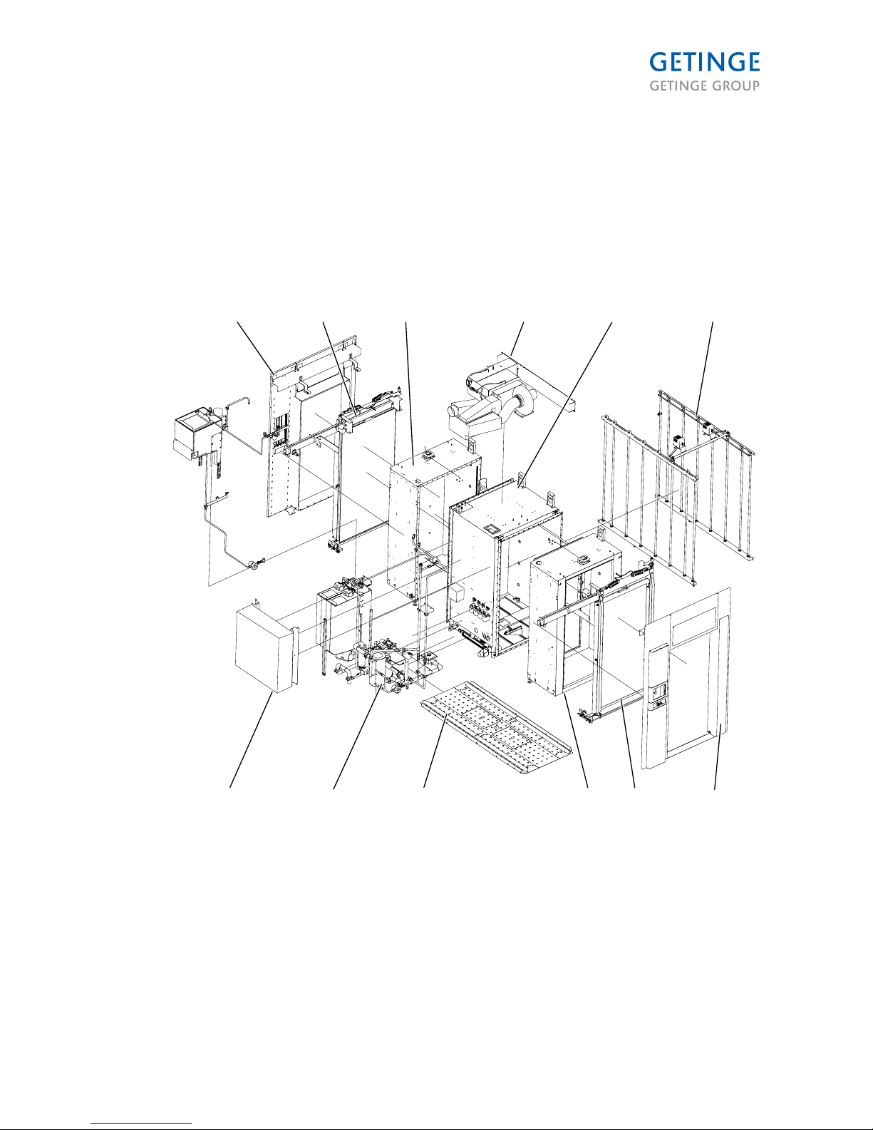
The washer-disinfector is shipped in separate modules. Only personnel from Getinge Desinfection AB or
personnel trained by Getinge Desinfection AB may assemble the modules and install the machine.
Before installation, the installation area must be prepared with connections for water, electricity, steam
and waste water as per the information in Installation drawings, Page 65, TECHNICAL DATA, Page
81 and Electrical connection, Page 52.
An example showing how the machine is delivered in modules.
001726
1
7 8 9 3 2 1
2 3 4 5 6
1. Panel package module (load end, unload
end)
2. Glass Door Module
3. Chamber Extension Module
4. Dryer module
5. Core Module
6. Side spraying module
7. Electrical cabinet module
8. Heater, pump & piping module
9. Chamber Floor Module
Page 11 of 92
<Doc_INS><Doc_6001341302><Rel.A><Lang_en>
Page 12
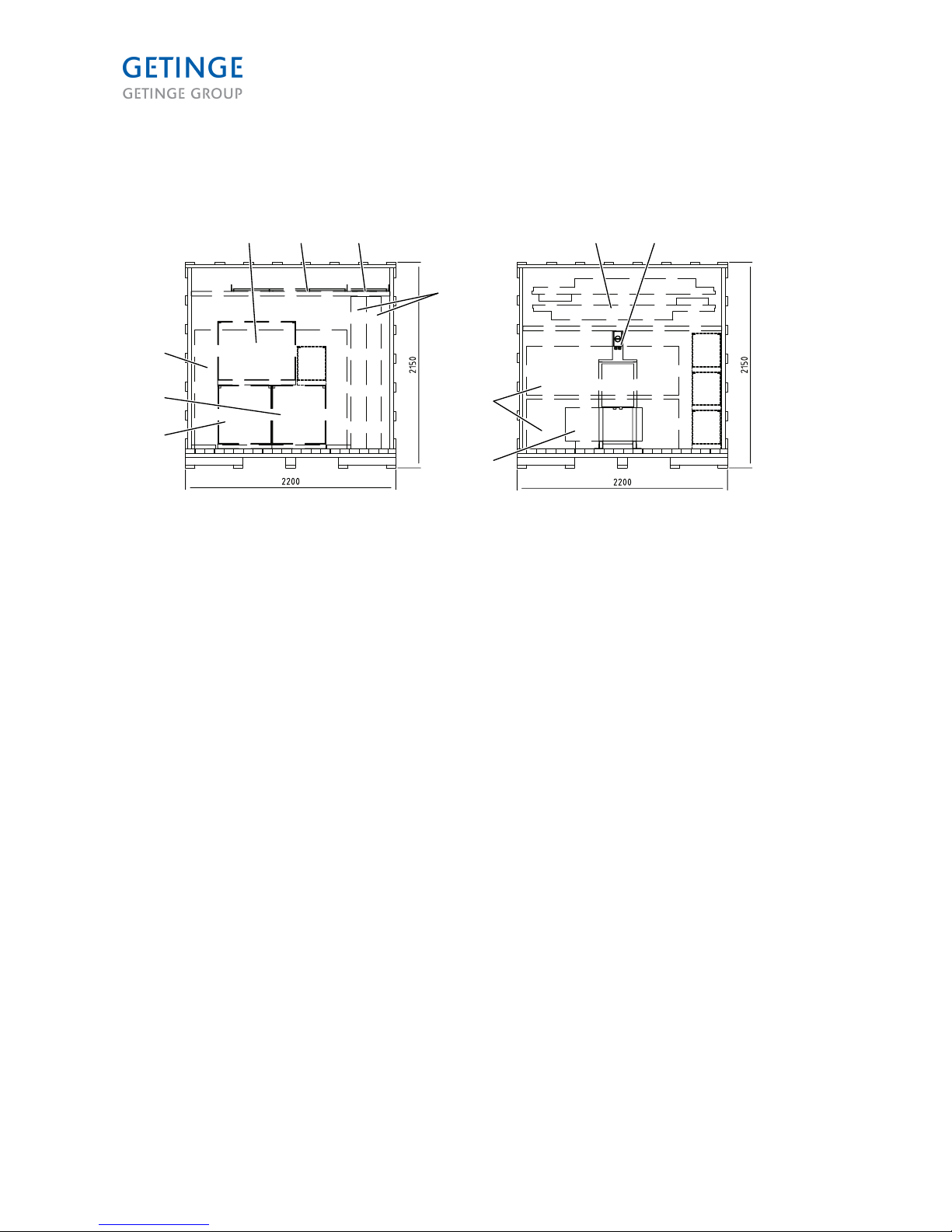
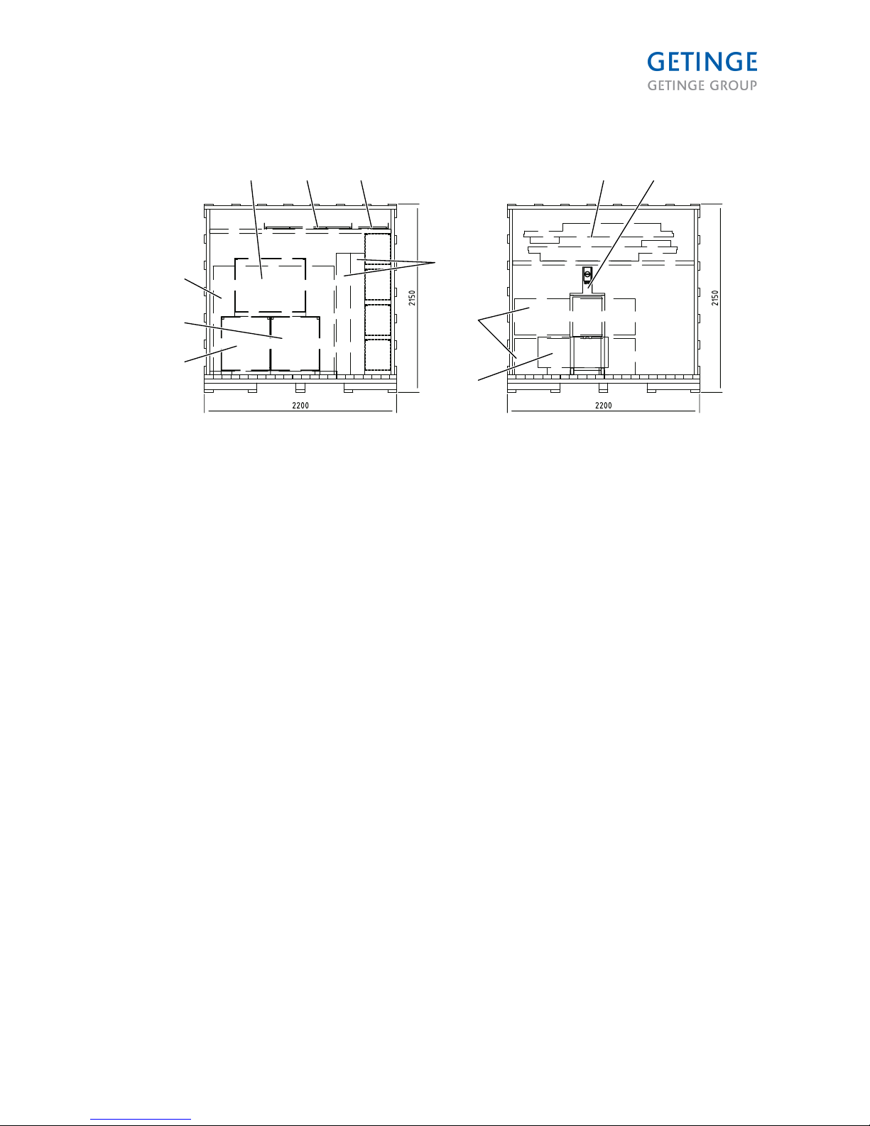
Unpacking
Packaging 9122
R
T
S
S
8
9
104 5
7
11
1
2
3
001728
6
1. Core Module
2. Dryer module
3. Heater, pump & piping module
4. Waste water, saving and booster tank
5. Chamber Floor Module
6. Module with front panel for service door
(option)
7. Glass doors
8. Chamber Extension Module
9. Electrical cabinet
10. Panel package module (load end, unload
end)
11. Transformer, complete
Packaging L=2850 Packaging L=3020
Core Module Chamber Extension Module
Dryer module Transformer, complete
Heater, pump & piping module Electrical cabinet
Glass doors Door rails 2 pcs (S)
Waste water, water-saving tank and booster tank Beams and pipes (R)
Chamber Floor Module Panel package module (load end, unload end)
Door locking lower (T)
Page 12 of 92
<Doc_INS><Doc_6001341302><Rel.A><Lang_en>
Page 13
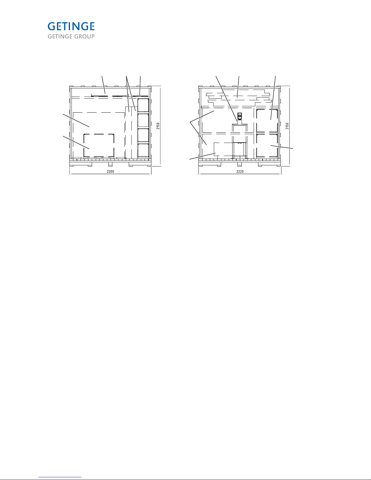
Packaging 9120
4
1
2
3
8
9
5
7
10 11
T
R
S
S
6
001730
1. Core Module
2. Dryer module
3. Heater, pump & piping module
4. Waste water, saving and booster tank
5. Chamber Floor Module
6. Module with front panel for service door
(option)
7. Glass doors
8. Chamber Extension Module
9. Electrical cabinet
10. Panel package module (load end, unload
end)
11. Transformer, complete
Packaging L=2850 Packaging L=2850
Core Module Chamber Extension Module
Dryer module Transformer, complete
Heater, pump & piping module Electrical cabinet
Glass doors Panel package module (load end, unload end)
Waste water, water-saving tank and booster tank
Chamber Floor Module
Door locking lower (T)
Door rails 2 pcs (S)
Beams and pipes (R)
Page 13 of 92
<Doc_INS><Doc_6001341302><Rel.A><Lang_en>
Page 14
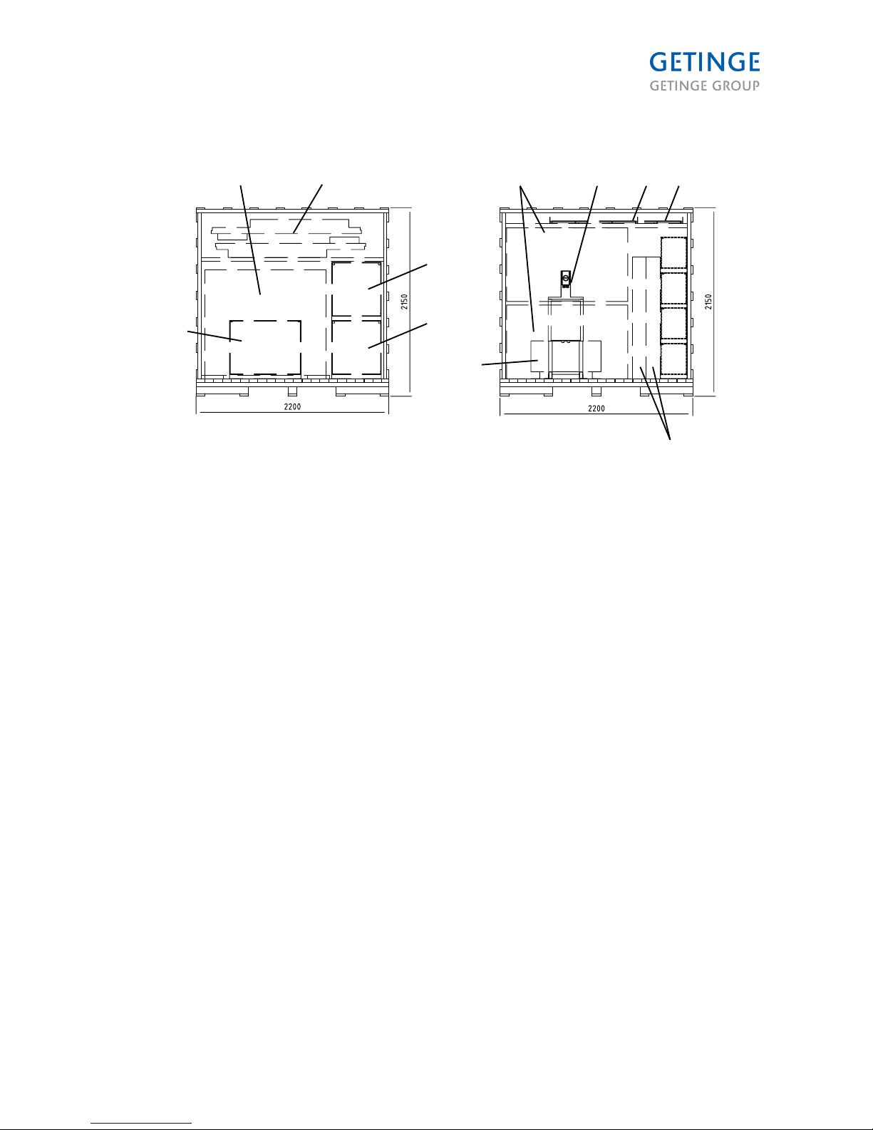
Packaging 9125
3
1
2
6
7
11
8 9 10
T
R
S
S
54
001731
1. Core Module
2. Waste water, saving and booster tank
3. Chamber Floor Module
4. Glass doors
5. Module with front panel for service door
(option)
6. Chamber Extension Module
7. Electrical cabinet
8. Transformer, complete
9. Panel package module (load end, unload
end)
10. Dryer module
11. Heater, pump & piping module
Packaging L=2850 Packaging L=2850
Core Module Chamber Extension Module
Glass doors Dryer module
Waste water, water-saving tank and booster tank Heater, pump & piping module
Chamber Floor Module Transformer, complete
Door locking lower (T) Electrical cabinet
Door rails 2 pcs (S) Panel package module (load end, unload end)
Beams and pipes (R)
Page 14 of 92
<Doc_INS><Doc_6001341302><Rel.A><Lang_en>
Page 15
Packaging 9128
R
S
S
T
2 3 7 8 9 10
1
4
5
6
11
001732
1. Waste water, saving and booster tank
2. Core Module
3. Panel package module (load end, unload
end)
4. Dryer module
5. Heater, pump & piping module
6. Electrical cabinet
7. Chamber Extension Module
8. Transformer, complete
9. Chamber Floor Module
10. Module with front panel for service door
(option)
11. Glass doors
Packaging L=2850 Packaging L=3020
Core Module Chamber Extension Module
Waste water, water-saving tank and booster tank Glass doors
Dryer module Transformer, complete
Heater, pump & piping module Electrical cabinet
Panel package module (load end, unload end) Chamber Floor Module
Door locking lower (T)
Door rails 2 pcs (S)
Beams and pipes (R)
Page 15 of 92
<Doc_INS><Doc_6001341302><Rel.A><Lang_en>
Page 16
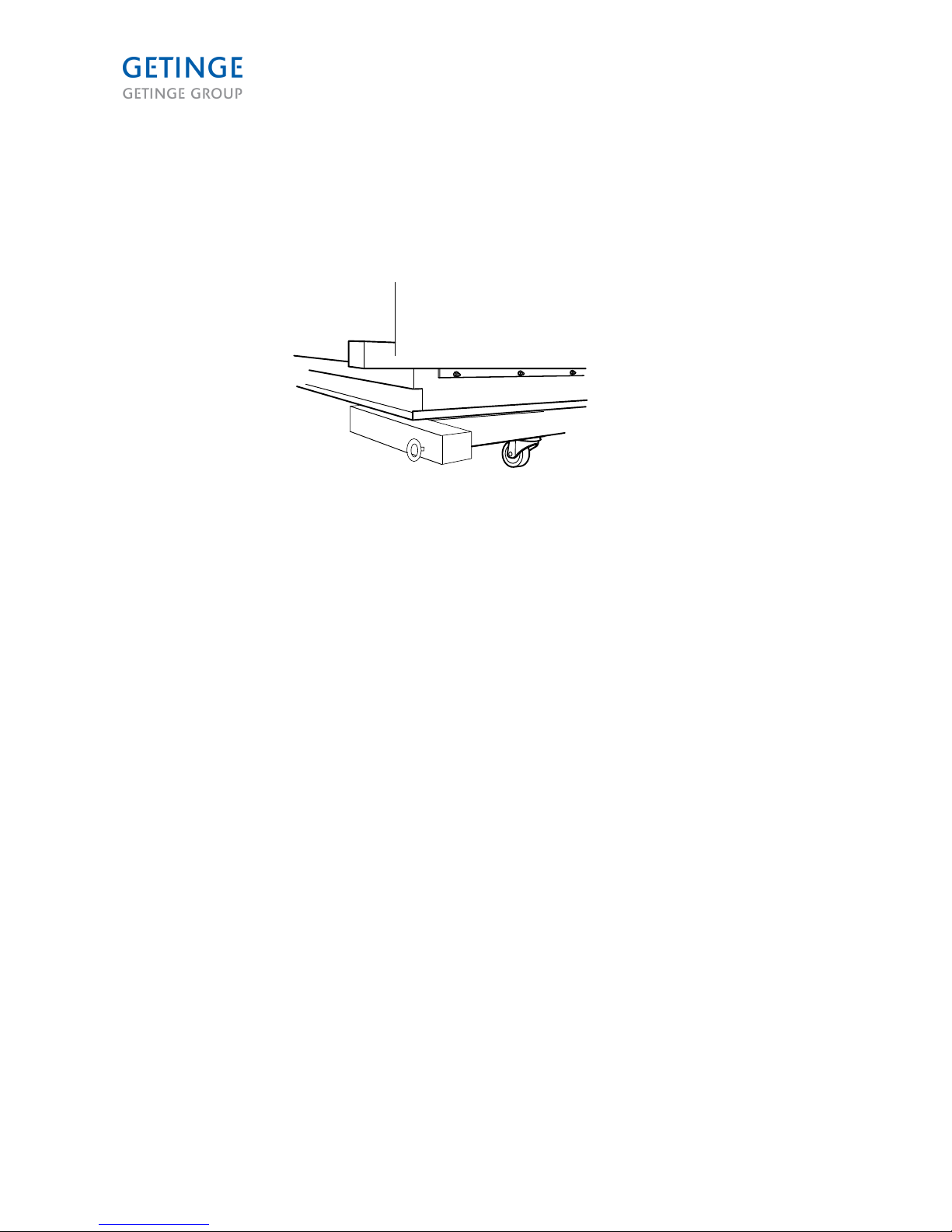
Assembly
Installation begins with assembly of the main modules. This module is affixed to four corner supports.
Four wheels could be mounted on the supports to facilitate transportation to the pit. There are two eye
bolts that can be screwed into the corner supports. These can be used as lifting aids.
• Move the main module and the chamber extension modules to the installation space.
000523
• Measure up exactly where the module will be located. Place four pieces of metal sheeting in the
pit for the module's legs. (The sheeting makes it easier to move the module later on.)
Page 16 of 92
<Doc_INS><Doc_6001341302><Rel.A><Lang_en>
Page 17
• Adjust the adjustable feet, so the module is level with the floor of the room. If the washerdisinfector is to be installed in a pit, it is a good idea to measure the depth of the pit before
adjusting the feet. If the pit's depth is 150 mm, the adjustable feet must be lengthened approx.
50 mm, as illustrated below. This means that the extended length of the feet must be 100 mm
less than the depth of the pit.
50 mm
000634
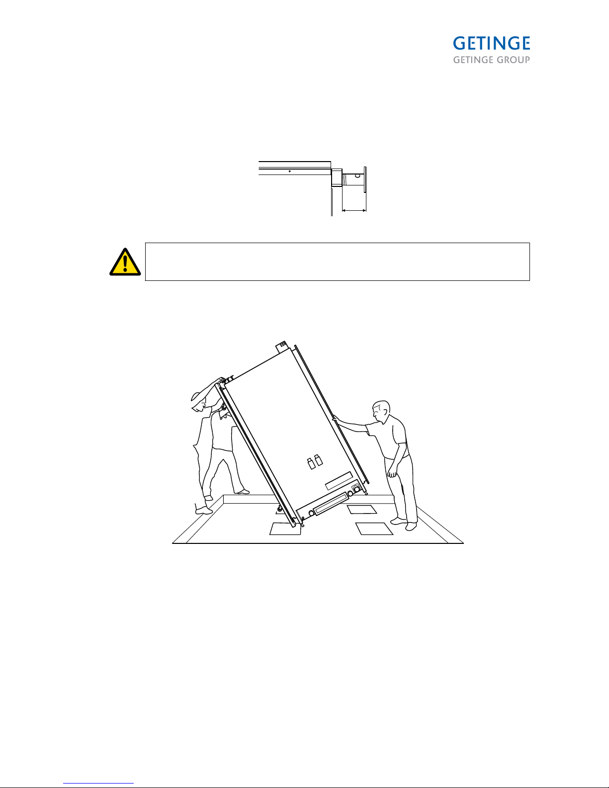
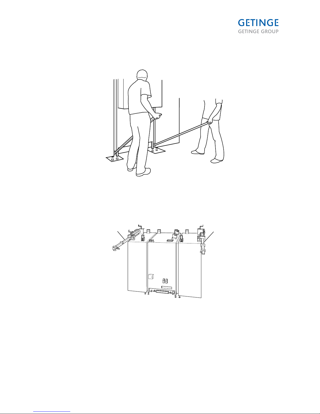
Three people are required for this step. Two to lift the module and one to hold the
rear of the module.
• Lower the lower end of the module into the pit, stand it on the front pair of wheels and push it
towards the middle of the pit. Lift the module into a vertical position and check that the
module's legs are on the pieces of plating.
000524
Page 17 of 92
<Doc_INS><Doc_6001341302><Rel.A><Lang_en>
Page 18
• Remove the packing frame.
• Clean the surface where the sealing strip is to be placed.
• Place the sealing strips on the two ends of the main module.
• Apply silicone in the lower corners of both ends of the module. Apply the silicone from the
corner and about 20 cm up along the edge where the strip will be placed. Also apply silicone
from the corner and about 20 cm in towards the middle of the main module, along the edge
where the strip will be located.
Note: It is very important that the sealing strip follows the edge of the seal plate.
Be sure not to take any short cuts in the corners.
000633
1
1
1
1
1
1
1. Sealing strip
Page 18 of 92
<Doc_INS><Doc_6001341302><Rel.A><Lang_en>
Page 19
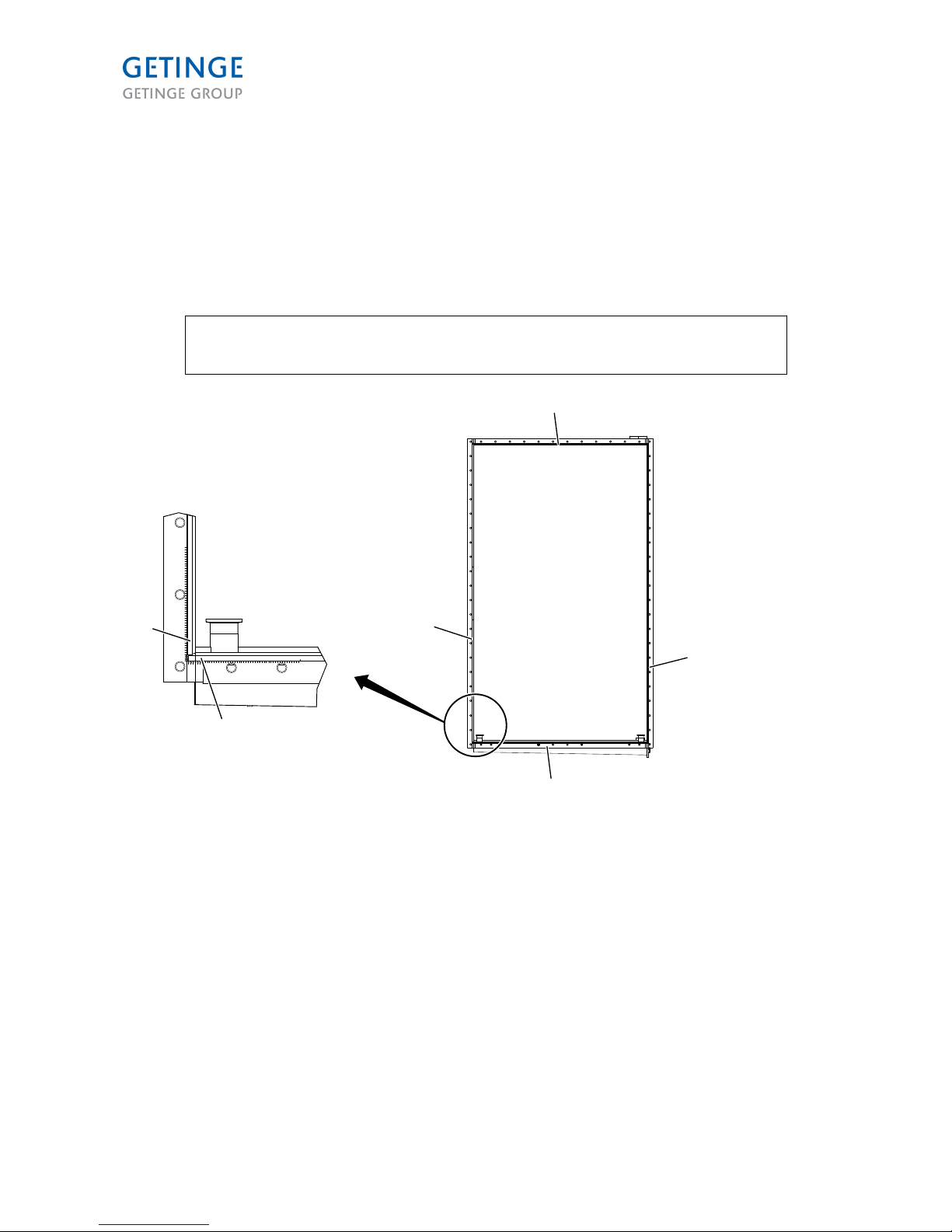
• Repeat the following steps (1-4) for modules with a chamber extension.
1. Get one of the modules with chamber extension and adjust the feet so that the module is level
with the main module. If the washer-disinfector is to be installed in a pit, it is a good idea to
measure the depth of the pit before adjusting the feet. If the pit's depth is 150 mm, the
adjustable feet must be lengthened approx. 50 mm, as illustrated below. This means that the
extended length of the feet must be 100 mm less than the depth of the pit.
50 mm
000634
2. Move the extension module against the main module and insert (do not pull out yet) the top
screw on both sides, to attach the module with chamber extension to the main module.
3. Insert the two guide pins on the floor edge of the chamber extension module into the
corresponding holes in the main module, and move the module for chamber extension towards
the main module.
000635
1
1. Locating pins
Note: Use the silicone seal 732 that comes with the machine. Let the silicone
harden for 12 hours before using the machine.
Page 19 of 92
<Doc_INS><Doc_6001341302><Rel.A><Lang_en>
Page 20
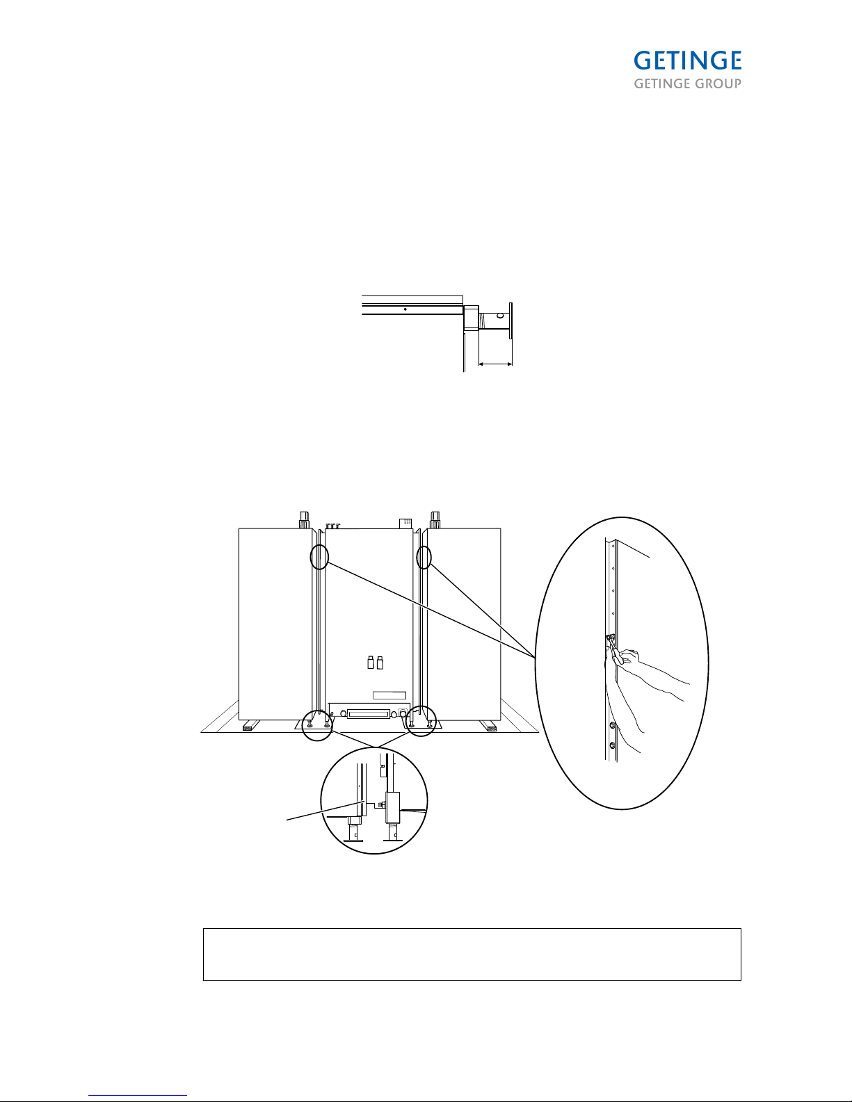
4. Screw the chamber extension module to the main module. Check that the seal is sitting
correctly before screwing on the chamber extension modules. Fill the gap between the modules
on the inner side of the chamber with silicone, the entire lower part and about 20 cm up the
walls.
• Fit the limit switch for closed door to each chamber extension module.
000525
• Adjust the chamber floor in relation to the floor level (tolerance 0 to +2 mm). The chamber floor
must be level with or slightly above the building's floor level. Use a straight-edge ruler and a
level. Check and adjust using the four machine feet and a crowbar.
000521
Page 20 of 92
<Doc_INS><Doc_6001341302><Rel.A><Lang_en>
Page 21
• Position the machine correctly. Use a lever to adjust the position of the machine.
000534
• Check that the floor of the chamber is level with the floor if installing the washer-disinfector in a
pit. Adjust the chamber floor as needed, according to the instructions in previous steps.
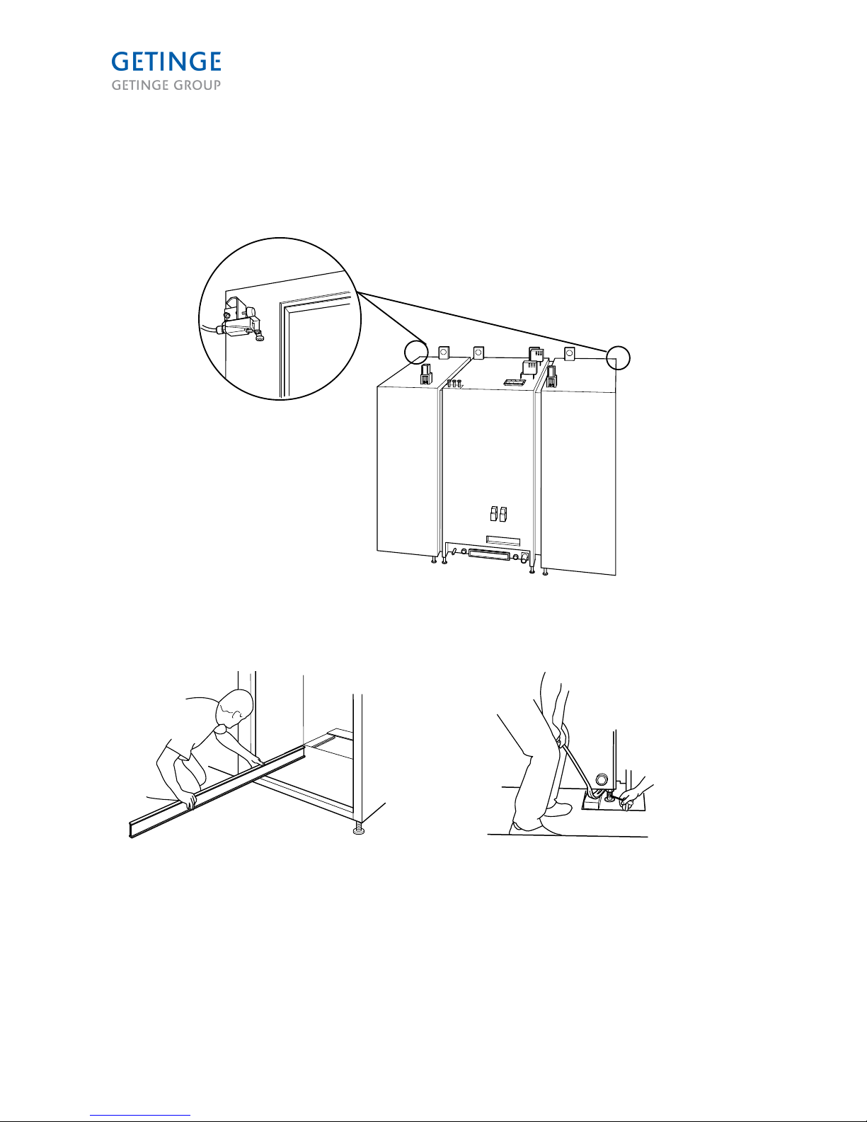
• Lift up and fit the two door rails on the roof.
• Install the distribution canal.
1 1
000637
1. Door rail
Page 21 of 92
<Doc_INS><Doc_6001341302><Rel.A><Lang_en>
Page 22
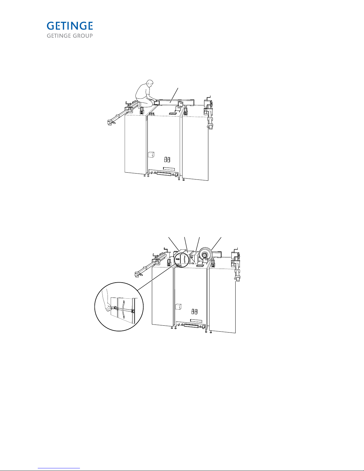
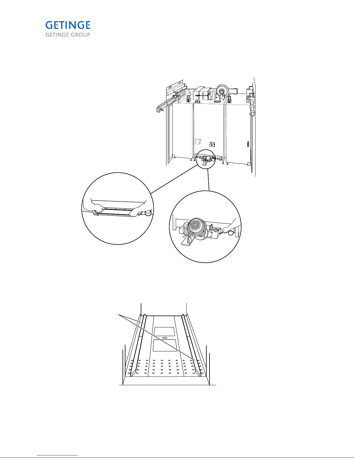
• Install the Dryer module.
• Position the filter and air duct.
1
000638
1. Air duct
• Install the fan.
• Attach the filter and the air duct to the heating element with tension straps.
1 2 3 4
001734
1. Air duct
2. Filter
3. Heating element
4. Fan
Page 22 of 92
<Doc_INS><Doc_6001341302><Rel.A><Lang_en>
Page 23
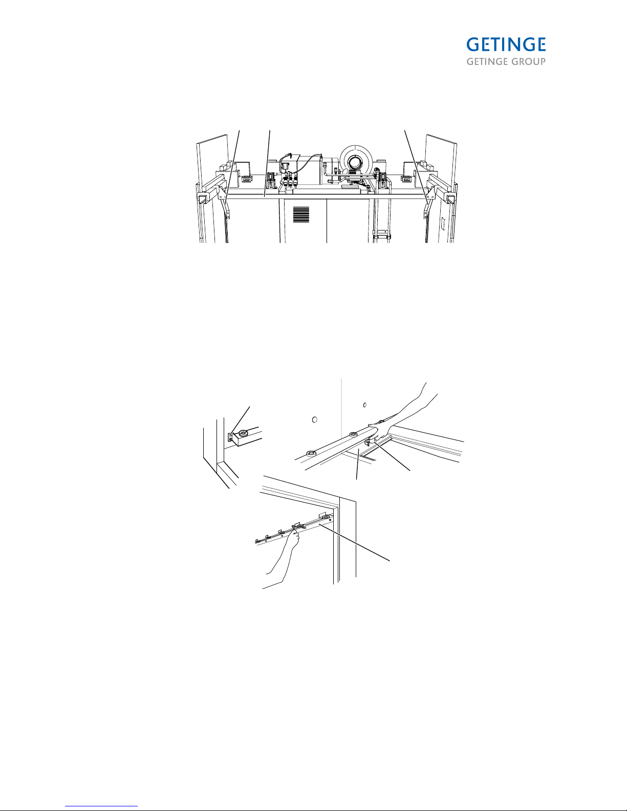
• Install the two brackets and the support beam between them.
1 2
001753
1
1. Brackets
2. Support beam
• Install two distribution pipes inside the chamber. Attach the pipes with a tri-clamp to the water
connection on the underside and with two screws at each end. Start by connecting the
distribution pipe to the water connection on the service side of the machine. Then tighten the
screws.
4
1
2
3
000640
1. Screw
2. End cover
3. Tri-clamp
4. Upper bracket
Page 23 of 92
<Doc_INS><Doc_6001341302><Rel.A><Lang_en>
Page 24
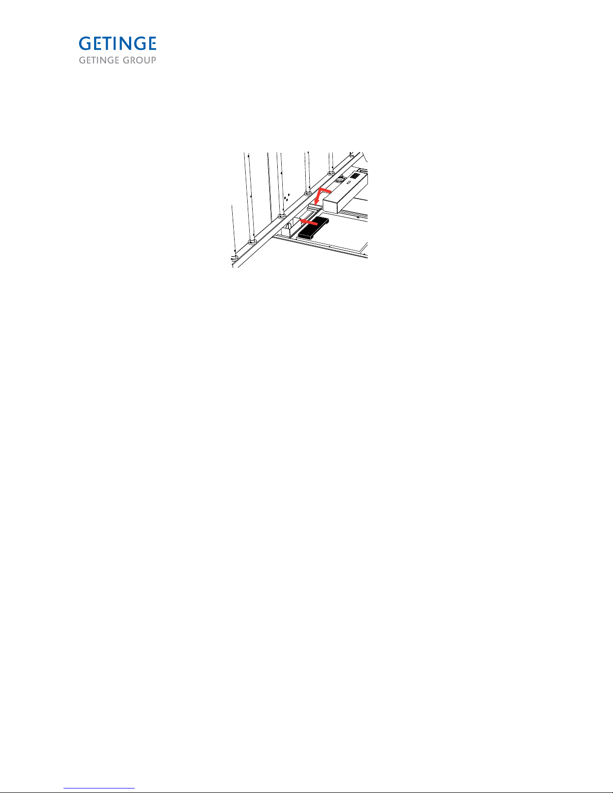
• Fit the blower protection cover (the black cover) over the overflow box. Install metal cover over
the box. Push the slotted metal flap downwards (90° angle) to keep the blow protector in the
proper position. Make sure that the black casing can move freely between the trap and the
edge of the casing.
000520
Page 24 of 92
<Doc_INS><Doc_6001341302><Rel.A><Lang_en>
Page 25
Risk of crushing when the chamber floor is lowered.
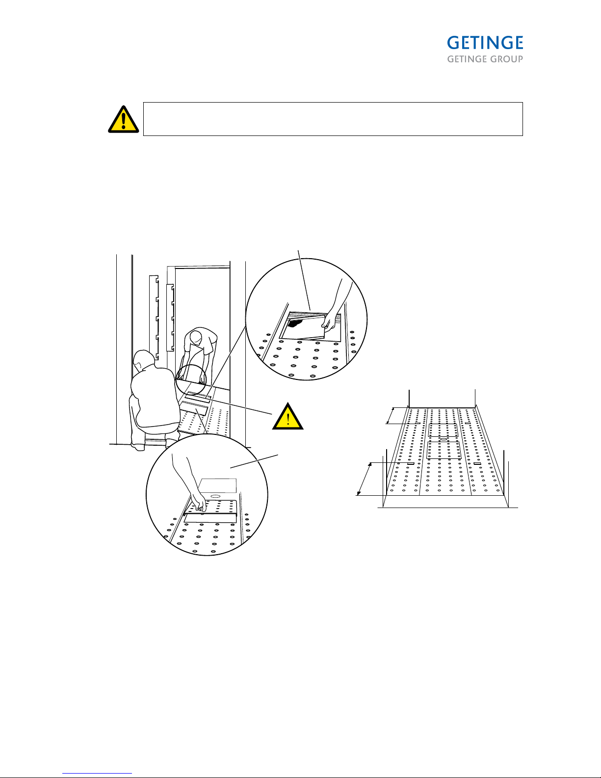
• Install the Chamber floor module. Be careful to place the module in the right direction. The
loading side on the chamber floor is farther from the marks for the wash cart. Check by
measuring or calculating the number of holes before the marks.
• Place four coarse strainers in the two holes on the floor plate and place the service panel over
the two holes. (For 9122 there are also two 105 mm spacers to be placed closest to the
chamber walls.)
B
A
C
001736
2
1
1. Coarse strainer 2 x 4 pce
2. Two service panels
A. Loading side
B. Short
C. Long
Page 25 of 92
<Doc_INS><Doc_6001341302><Rel.A><Lang_en>
Page 26
• Place the sealing for the pump module in its groove (A).
• Install the pump module with seven screws (B).
001735
B
A
• Install the profiles for guiding the goods trolley in the machine (adjustable). Place them so that
the cart docking aligns exactly with the floor docking. (Normally they are placed in the second
line of holes from the wall)
1
001737
1. Profiles
Page 26 of 92
<Doc_INS><Doc_6001341302><Rel.A><Lang_en>
Page 27

• Fit the two upper fittings for the nozzle pipes, (one on either side of the chamber).
• Place the springs in the holes of the distribution pipes and place a teflon washer at the top of
the spring.
000516
• Install the nozzle pipes on both sides. Press them down towards the springs and pass them
through the holes in the upper bracket.
Note: The left arms should point towards the wall. See illustration below.
• Attach the two link arms to run in the reciprocal direction. The holes in the link arms are not
centered. Make sure that the edge closest to the hole is placed against the wall.
1
2
3
000643
1. Nozzles
2. Link arms
3. The edge nearest the hole must be facing the wall.
Page 27 of 92
<Doc_INS><Doc_6001341302><Rel.A><Lang_en>
Page 28
• Install the two long, narrow lifting rods with threads and nuts at the top edge and the eyelet at
the bottom edge (to tilt the chamber).
Screw into the sleeve at the top and tighten the
locknut (A).
Screw the eyelet to the floor plate (B).
A
000532
B
Page 28 of 92
<Doc_INS><Doc_6001341302><Rel.A><Lang_en>
Page 29

• Position the six guard rails in the holders on the wall of the chamber.
000543
Page 29 of 92
<Doc_INS><Doc_6001341302><Rel.A><Lang_en>
Page 30

• Fit the door seals. Hold the outside of each seal part to prevent the sealing strip bladder from
returning to the normal position because of vacuum.
001738
Page 30 of 92
<Doc_INS><Doc_6001341302><Rel.A><Lang_en>
Page 31

• Line up the doors with their mountings in the door rails. Fit screws and nuts. Move the door
sideways to the middle of the door rail. Push the door upwards to insert the brackets into the
rail against the force of the spring, and lower the door into the pit. (If this method does not work
because there is too little space in the pit, lower the door into the pit first and then insert from
below, so the door can be attached to the brackets.)
000530
• The wire should be treaded as shown in the illustration below.
000531
Page 31 of 92
<Doc_INS><Doc_6001341302><Rel.A><Lang_en>
Page 32

• Install the thresholds with three screws on each side.
• Place two plastic slider blocks on the moving part of the threshold.
1
000644
1. Plastic sliding blocks
• Place the electrical cabinet with the door facing down.
1
2
3
000636
• Fit two temporary supports with four screws and four nuts.
1. Electrical cabinet
2. Temporary supports for installing the electrical
cabinet
3. Wood beams
Page 32 of 92
<Doc_INS><Doc_6001341302><Rel.A><Lang_en>
Page 33

• Stand the cabinet up with the help of the temporary supports. Place some wooden blocks
against the legs of the machine to get the right point of rotation.
001733
Note: Make sure that the lifting eyes are correctly tightened.
• Hang the cabinet from the top edge of the machine in the main module.
• Remove the temporary supports and secure the electrical cabinet with four screws.
000536
Page 33 of 92
<Doc_INS><Doc_6001341302><Rel.A><Lang_en>
Page 34

• Place the lower plastic guide in the hole.
• Insert the first of the two upper plastic guides on to the rod and place the rod in the upper
bracket.
• Insert the rod into the lower plastic guide.
• Position the lower locking plate of the upper bracket and tighten the plastic guide from below.
• Place the second upper plastic guide on the rod from above and the locking plate from below.
Tighten the plastic guide.
000645
1
2
1. Upper plastic guides
2. Lower plastic guides
Page 34 of 92
<Doc_INS><Doc_6001341302><Rel.A><Lang_en>
Page 35

• Fit outer plates with panel (nine screws at the bottom edge and four screws at the top edge).
• Install and adjust the black round piece of Delrin so that the threshold plate can be moved
easily but is held back by the back edge.
• Adjust the height as needed in the manner described earlier.
2
1
3
000648
1. Screws at the top edge
2. Screws at the bottom edge
3. Delrin block
• Apply silicone to the joint between the threshold and the extension module. Clean the surface
before applying the silicone.
002927
Page 35 of 92
<Doc_INS><Doc_6001341302><Rel.A><Lang_en>
Page 36

• Install pipe bends (90°) with a tri-clamp.
001739
• Attach the link arms from the piston rod to the rod and attach the door closure emergency
release spring (two on each side of the machine).
000646
1
1. Link arm
Page 36 of 92
<Doc_INS><Doc_6001341302><Rel.A><Lang_en>
Page 37

• Install the support beams for the “door sealing shafts”.
1
2
000647
1. Support leg beam
2. Screws
Page 37 of 92
<Doc_INS><Doc_6001341302><Rel.A><Lang_en>
Page 38

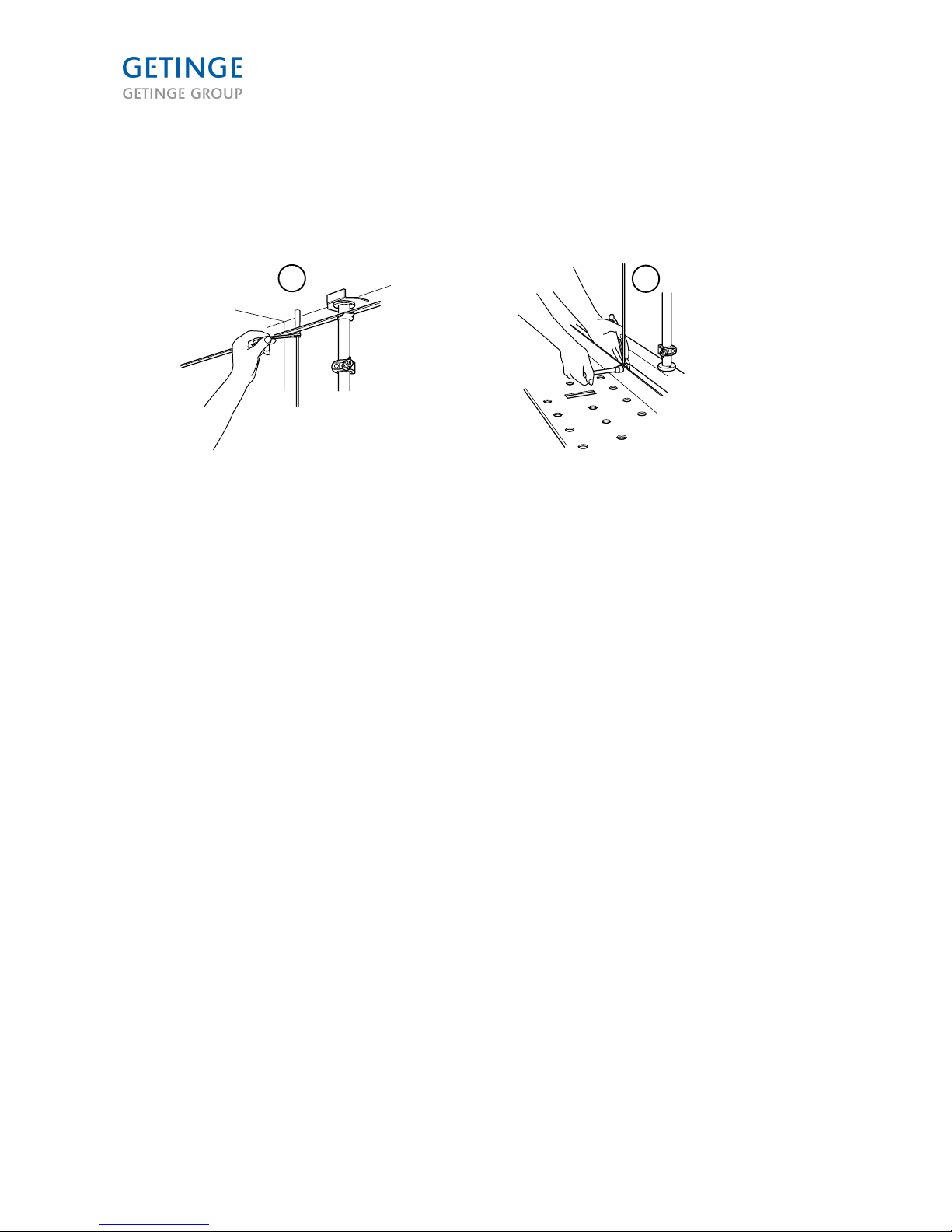
• Pull the safety line inside the chamber through the hole in the chamber wall.
000527
• Install the bracket with the safety line switch on the outside. Connect the hook from the wire
end to the bottle screw. Next connect the bottle screw to the safety wire's switch.
• Secure the end of the wire to the eyelet inside the chamber using a pin.
4
1
2
3
000649
1. Bracket
2. Safety line breaker
3. Bottle screw
4. Eyelet in chamber
• Adjust with bottle screw, so the arrow aligns with the line at the position indicator.
1
001740
1. Position indicator
Page 38 of 92
<Doc_INS><Doc_6001341302><Rel.A><Lang_en>
Page 39

• Install all the cable ducts (18) and the cable tray.
001741
K209
K206
K104
K208
K207
K107
K205
K106
K105
K109
K212
K110
K213
K108
K101
K201
K211
K102
K103
K202
K204
K203
K210
Model 9120
Marking on drawing Quantity Length (mm) Installed/Not installed
K 205/106 1 Not installed
K 206/210 2 2000 Not installed
K105 1 440 Not installed
K 208/213/108/110/209 5 1000 All installed except K 209
K 204 1 750 Installed
K 203 1 590 Installed
K 103 1 690 Installed
K 107.2/109.2 2 500 Not installed
K 207/212 4 590 Not installed
K 107.1/109.1 2 660 Not installed
Page 39 of 92
<Doc_INS><Doc_6001341302><Rel.A><Lang_en>
Page 40

Model 9120
Marking on drawing Quantity Length (mm) Installed/Not installed
K 211 1 270 Not installed
K 104 1 330 Not installed
K 102 1 400 Installed
K 202 1 600 Installed
K 101/201 2 1000 Not installed
Model 9122
Marking on drawing Quantity Length (mm) Installed/Not installed
K 205/106 1 Not installed
K 206/210 2 2000 Not installed
K 105 1 650 Not installed
K 208/213/209 3 1000 All installed except K 209
K 108/110 2 1300 Installed
K 204 1 750 Installed
K 103/203 2 800 Installed
K 107/109/207/212 4 1300 Not installed
K 211 1 270 Not installed
K 104 1 330 Not installed
K 102 1 440 Installed
K 202 1 600 Installed
K 101/201 2 1000 Not installed
Model 9125
Marking on drawing Quantity Length (mm) Installed/Not installed
K 205/106 1 Not installed
K 206/210 2 2000 Not installed
K105 1 440 Not installed
K 208/213/108/110/209 5 1000 All installed except K 209
K 204 1 750 Installed
K 203 1 590 Installed
K 103 1 690 Installed
K 107/109/207/212 4 1000 Not installed
K 102/211 2 400 K102 Not installed, K211
Installed
K 104 1 470 Not installed
K 202 1 600 Installed
K 101/201 2 1000 Not installed
Page 40 of 92
<Doc_INS><Doc_6001341302><Rel.A><Lang_en>
Page 41

Model 9128
Marking on drawing Quantity Length (mm) Installed/Not installed
K 205/106 1 Not installed
K 206/210 2 2000 Not installed
K105 1 440 Not installed
K 208/213/108/110/209 5 1000 All installed except K 209
K 204 1 750 Installed
K 203 1 590 Installed
K 103 1 690 Installed
K 107/109/207/212 4 1000 Not installed
K 102 1 400 Not installed
K 104 1 650 Not installed
K 202/211 2 600 K 202 Installed, K211 Not
installed
K 101/201 2 1000 Not installed
• The electrical cables are connected and coiled at the various loads. Draw the cables in the
cable ducts as shown in the illustrations below and connect them in the electrical cabinet.
• The cables for 230/400 V must be placed in the cable duct/tray with the number K1xx (cable
ducts for 24 V cables have number K2xx) as shown in the illustration on the previous page. All
cables for 230/400 V must be connected to the electrical cabinet via cable duct K102 at the
cabinet entrance on the left side. If the object is on the right side of the electrical cabinet, the
cables must be drawn over the machine in the cable tray marked K106 above the chamber.
Place remaining cable in the cable tray on top of the machine marked K106.
A
001742
A. 230 V/400 V cables
Page 41 of 92
<Doc_INS><Doc_6001341302><Rel.A><Lang_en>
Page 42

• The cables for 24 V must be placed in a cable duct/tray with the munber number K2xx as
shown in the illustration on the previous page. All cables for 24 V must be connected to the
electrical cabinet via cable duct K202 at the entrance to the cabinet on the right side. If the
object to which the cable is to be drawn is on the left side of the cabinet, the cables must be
drawn over the machine via cable tray marked K205 above the chamber. Place excess cable in
the cable tray on the top of the machine marked K205.
A
1
1
001743
1. Cable split
A 24 V Cables
Page 42 of 92
<Doc_INS><Doc_6001341302><Rel.A><Lang_en>
Page 43

• Connect the cable from the door modules, soiled side (SS) and clean side (CS, option) to the
cable splits. Connect from the SS door equipment to cable split X215 with cables 251...
Connect from the CS door equipment to cable split X220 with cables 261...
000540
-X257 (C.S)
-X267 (S.S)
-X256 (C.S)
-X266 (S.S)
-X255 (C.S)
-X265 (S.S)
-X252 (C.S)
-X262 (S.S)
-X251 (C.S)
-X261 (S.S)
-X220 (C.S)
-X215 (S.S)
Jack
Cable label Destination
1 -X251
-X261
Door SS Unlock 1 Switch S02.1
Door CS Unlock 1 Switch S06.1
2 -X252
-X262
Door SS Unlock 2 Switch S02.2
Door CS Unlock 2 Switch S06.2
3 Not used.
4 Not used.
5 -X255
-X265
Door SS Threshold Switch S11
Door CS Threshold Switch S12
6 -X256
-X266
Door SS Locked 1 Switch S01.1
Door CS Locked 1 Switch S05.1
7 -X257
-X267
Door SS Locked 1 Switch S01.2
Door CS Locked 1 Switch S05.2
8 Not used.
Page 43 of 92
<Doc_INS><Doc_6001341302><Rel.A><Lang_en>
Page 44

• Install the two chamber temperature sensors for the chamber in the chamber wall.
000528
• Install the transmitter for differential pressure and the temperature sensor on the dryer unit.
2
1
001744
1. Temperature sensor
2. Transmitter for differential pressure
Page 44 of 92
<Doc_INS><Doc_6001341302><Rel.A><Lang_en>
Page 45

• The air hoses are secured and coiled at the various loads. Draw the air hoses and attach them
as shown in the illustration below and connect them to the respective air valve.
001745
PORT B PORT A
Y31 DOOR LOCK (CS) 530 Y21 DOOR LOCK (SS) 527
RESERVE Y22 FILL FROM BOOSTER TANK 535
Y18 NEUTRALIZATION 534 Y17 LOW LEVEL - DRAINAGE 533
Y30 THRESHOLD (CS) FRONT INTAKE 526 Y30 THRESHOLD (CS) 525
Y20 THRESHOLD (SS) FRONT INTAKE 524 Y20 THRESHOLD (SS) 523
Y09 SPLIT WATER CIRCUIT 518 Y09 SPLIT WATER CIRCUIT 517
Y19 WASH CART INCLINE 514 Y04 FILTER DRAINAGE 513
Y14 FROM WASTE WATER TANK 2 512 Y13 TO WASTE WATER TANK 2 511
Y12 FROM WASTE WATER TANK 1 510 Y11 TO WASTE WATER TANK 1 509
Y10 AVRFS 508 Y10 DRAINAGE TANK 507
Y06 STEAM, CHAMBER 506 Y05 STEAM, DRYER UNIT 505
Y07 STEAM, BOOSTER TANK 504 Y03 HQ WATER 503
Y02 HOT WATER 502 Y01 COLD WATER 501
Page 45 of 92
<Doc_INS><Doc_6001341302><Rel.A><Lang_en>
Page 46

• Install the heater module with a “tri-clamp”.
1
CW HW DW
001746
1. Heater module
• Install the filter pipe module with a tri-clamp.
1
001747
1. Strainer pipe module
Page 46 of 92
<Doc_INS><Doc_6001341302><Rel.A><Lang_en>
Page 47

• Install the waste water tank with two screws. Secure the hose on the drainage pump with hose
clamps.
1. Tanks
2. Hose to drain pump
• Install the waste water pipe between tank and drain. Install the hose between the filter pipe and
the drain.
1 2
001749
1. Drain pipes
2. Hose
Page 47 of 92
<Doc_INS><Doc_6001341302><Rel.A><Lang_en>
Page 48

• Install the vent pipe.
001750
1
1. Vent pipe
Page 48 of 92
<Doc_INS><Doc_6001341302><Rel.A><Lang_en>
Page 49

• Install the lower part of the steam pipe in the chamber wall and to the pipe at the heater
module.
1
001751
1. Lower part of steam pipe
Page 49 of 92
<Doc_INS><Doc_6001341302><Rel.A><Lang_en>
Page 50

• Install the upper steam pipe unit between the pipe in the lower steam pipe section and the
heating element. Attach the module on the chamber wall.
• Connect the air hoses to the two valves on the steam pipe unit.
• Install the steam pipes on top of the chamber.
1
001752
2 4
3
3
1. Steam pipe
2. Heating element
3. Valve
4. Upper steam pipe unit
Page 50 of 92
<Doc_INS><Doc_6001341302><Rel.A><Lang_en>
Page 51

• Install the heat exchanger and let the outer end rest on the support beam. Attach the hose
using hose clamps. Do not forget the drainage hose.
1 2
001754
1. Heat exchanger
2. Hose
The water can leak from the spillway during a process or if a problem arises.
• Run the draining hoses from the thresholds to the gully.
002882
Page 51 of 92
<Doc_INS><Doc_6001341302><Rel.A><Lang_en>
Page 52

• Place the casing that covers the cables on the respective cable ducts.
• Fit the cover panels on the clean and soiled sides.
557100
0
1
1
1. Cover panel
Venting system
The venting system shall have an air gap of at least 50 mm direct after the exhaust. See drawing no.
5018514 for more information.
50 mm
1
001756
1. Not supplied by Getinge
Electrical connection
The electrical installation may only be performed by an authorized electrician.
The power supply cable is connected to the incoming connection terminals and the protective earth
connects to the ”PE” connection terminal.
Page 52 of 92
<Doc_INS><Doc_6001341302><Rel.A><Lang_en>
Page 53

Installation category
The electrical installation should be made in accordance with CAT II
Main switch
Om maskinen värms upp med ånga utan transformator måste maskinen förses med en separat, låsbar
brytarenhet i elförsörjningen. Huvudbrytaren ska sitta lättillgänglig på en vägg nära maskinen.
Installationen måste utföras och märkas enligt lokala bestämmelser. (Eluppvärmda maskiner har en
matningsbrytare och maskiner med transformator en huvudbrytare.)
Power supply cable transformer
Transformatorn ska anslutas till elskåpet av behörig elektriker. Kontrollera att anslutningsalternativen i
transformatorn är korrekt inställda för den aktuella installationen. Påsarna med kiselgel ska tas bort från
elskåpet och transformatorn innan maskinen används.
Power supply cable steam heated
Ingående kopplingsstyrkablar med en diameter på mellan AWG 18- 1/0. Matningskabeln måste
dimensioneras enligt lokala bestämmer men får inte vara mindre än AWG 12.
Power supply cable electrically heated
Ingående kopplingsstyrkablar med en diameter på mellan AWG 6- 1/0. Matningskabeln måste
dimensioneras enligt lokala bestämmer men får inte vara mindre än AWG 1/0.
Eluppvärmda maskiner måste skyddas med en säkring med egenskaperna 100 A kurva C.
EL
Rekommenderad
servicefrånkoppling
Primär transformator
Full belastningsström
Sekundär transformator Full
belastningsström (maskin)
Ånguppvärmning
200 V 50/60 Hz 3+PE 20 A kurva C 15,5 A 7,3 A
208 V 50/60 Hz 3+PE 20 A kurva C 15,2 A 7,3 A
220 V 50/60 Hz 3+PE 20 A kurva C 14,7 A 7,3 A
230 V 50/60 Hz 3+PE 20 A kurva C 14,3 A 7,3 A
240 V 50/60 Hz 3+PE 20 A kurva C 14,0 A 7,3 A
380 V 50/60 Hz 3+PE 16 A kurva C 8,5 A 7,3 A
400 V 50/60 Hz 3N+PE 16 A kurva C - (Ingen transformator) 7,3 A
415 V 50/60 Hz 3N+PE 16 A kurva C 7,1 A 7,3 A
480 V 50/60 Hz 3+PE 10 A kurva C 6,9 A 7,3 A
600 V 50/60 Hz 3+PE 10 A kurva C 5,0 A 7,3 A
Eluppvärmning
400 V 50/60 Hz 3N+PE 100 A kurva C - (Ingen transformator) 90 A
Page 53 of 92
<Doc_INS><Doc_6001341302><Rel.A><Lang_en>
Page 54

Adjusting the limit switch
Adjusting the pressure stabilizer
The pressure stabilizer is placed on the electrical cabinet and adjusted by pulling up the control knob and
then turning it. Adjust the stabilizer so the barometer displays 0.5 MPa of pressure.
001762
Open door
Manually open the door enough so the entire door is outside the door opening. Adjust the mechanical
end stop so it is against the door when the door is open all the way. The mechanical end stop consists of
an adjustable angle bracket and an adjustable rubber stopper.
001757
The switch's mounting is adjustable in two directions, which is used to adjust the switch's point of
impact. When adjusting for an open door, make sure that the point of impact for activated/non-activated
switches is distinct and that the breakpoint is not in the switch's outer area.
Page 54 of 92
<Doc_INS><Doc_6001341302><Rel.A><Lang_en>
Page 55

Closed door
Close the door manually so the door is symmetrical to the door opening. The mechanical end stop
consists of an adjustable angle plate that is adjusted according to the door.
With the door in a closed position, adjust the limit switch so it is activated by the door. The switch's
mounting allows for horizontal adjustment. When adjusting for an open door, make sure that the point of
impact for activated/non-activated switches is distinct and that the breakpoint is not in the switch's outer
area.
S04
001758
Adjusting the restrictor check valve
For smooth operation when opening and closing doors and when locking the threshold lock, use
restrictor check valves. Maneuver the doors manually by having a person hold down the button
to
open or the button to close while another person adjusts by turning the knob on the flow limiter.
001763
Page 55 of 92
<Doc_INS><Doc_6001341302><Rel.A><Lang_en>
Page 56

Crush protection, door
The switch for the door's crush protection is adjustable horizontally. Adjust the sensor's position so it is
as close to the crush protection plate as possible, without being activated.
15°
15°
001759
The sensor's joint can be adjusted as needed to achieve the right position.
Check that the point of impact for activated/non-activated switches is distinct and that the breakpoint is
not in the switch's outer area.
Threshold cylinder switch
The cylinder for threshold control is fitted with a sensor that indicates when the cylinder is fully extended.
2
1
001760
1. Sensor D1/D0
2. Sensitivity point
Activate manual mode for the digital output that controls the threshold cylinder
Test digital output
(2.1.6.8.2.4)
. Move the cylinder to its outer position. Move the sensor along the cylinder until it is
becomes activated, which is indicated by the sensor's built-in LED. Mark the position with a line on the
cylinder at the same level as the sensor's sensitivity point, which is marked on the sensor. Then continue
to move the sensor until it becomes non-activated, and mark this position on the cylinder. Place the
sensor so that its sensitivity point is centered between both marks.
Verify that the adjustment is correct by moving the threshold forward and backward. Adjust the restrictor
check valves to achieve a gentle and fluid motion.
Page 56 of 92
<Doc_INS><Doc_6001341302><Rel.A><Lang_en>
Page 57

Door locking switch
Two cylinders are used for door locking. The cylinders are fitted with two sensors, which indicate when
the door is locked or unlocked.
2
1
001761
1. Sensitivity point
2. Sensor D1/D0
Activate manual mode for the digital output that controls door locking
Test digital output (2.1.6.8.2.4)
.
Place the cylinder in its retracted position and move the sensor outward from the center until the sensor
is activated. Any activation is indicated by a built-in LED. Mark the position on the cylinder at the sensor's
sensitivity point. Continue to move the sensor until the sensor again becomes non-activated, and mark
the position. Position and fasten the sensor so the sensitivity point is centered between the marks.
Place the cylinder in its fully extended position and repeat the marking step and adjustment of the sensor
for the unlocked position. Make the same adjustment with the other cylinder.
Page 57 of 92
<Doc_INS><Doc_6001341302><Rel.A><Lang_en>
Page 58

Washer-disinfector options
One or two saving tanks
1 2
001764
1. Saving tank 1
2. Saving tank 2
Page 58 of 92
<Doc_INS><Doc_6001341302><Rel.A><Lang_en>
Page 59

Docking for items cart
1
001765
1. Cart docking
Page 59 of 92
<Doc_INS><Doc_6001341302><Rel.A><Lang_en>
Page 60

Waste cooling
1
001766
1. Waste cooling
Booster tank
1
001767
1. Booster tank
Page 60 of 92
<Doc_INS><Doc_6001341302><Rel.A><Lang_en>
Page 61

Neutralization system for waste water (pH sensor)
1
001768
1. pH sensor
Page 61 of 92
<Doc_INS><Doc_6001341302><Rel.A><Lang_en>
Page 62

Neutralization system for waste water (only time control)
1
001769
1. Neutralization system for waste water
Connection for treated water
1
001771
1. High-quality water valve
Page 62 of 92
<Doc_INS><Doc_6001341302><Rel.A><Lang_en>
Page 63

3rd and 4th dosage pump
1 2
001773
1. 3rd dosage pump
2. 4th dosage pump
Page 63 of 92
<Doc_INS><Doc_6001341302><Rel.A><Lang_en>
Page 64

Drying filter
2
1
001774
1. HEPA-filter
2. Heat exchanger
Page 64 of 92
<Doc_INS><Doc_6001341302><Rel.A><Lang_en>
Page 65

Installation drawings
9120, 9125, 9128 two doors, pit installation
577100
Page 65 of 92
<Doc_INS><Doc_6001341302><Rel.A><Lang_en>
Page 66

9120, 9125, 9128 one door, left, pit installation
677100
Page 66 of 92
<Doc_INS><Doc_6001341302><Rel.A><Lang_en>
Page 67

9120, 9125, 9128 one door, right, pit installation
777100
Page 67 of 92
<Doc_INS><Doc_6001341302><Rel.A><Lang_en>
Page 68

9120, 9125, 9128 pit installation
001778
Page 68 of 92
<Doc_INS><Doc_6001341302><Rel.A><Lang_en>
Page 69

9120, 9125, 9128 two doors, pit installation
977100
Page 69 of 92
<Doc_INS><Doc_6001341302><Rel.A><Lang_en>
Page 70

9120, 9125, 9128 one door, left, floor installation
0
87100
Page 70 of 92
<Doc_INS><Doc_6001341302><Rel.A><Lang_en>
Page 71

9120, 9125, 9128 one door, right, floor installation
001781
Page 71 of 92
<Doc_INS><Doc_6001341302><Rel.A><Lang_en>
Page 72

9120, 9125, 9128, front panels service
FRONT, Floor "RH"
FRONT, Pit "RH"
FRONT, "LH" LOAD
A
A
LOAD END (LH)
LOAD END
(RH)
LOAD END (LH)
* Loading ramp,
(floor mounted)
* Loading ramp,
(floor mounted)
2803 [9'-2
3
8
"] - Unit height
2650 [8'-8
3
8
"] - Unit height
3000 [9'-10
1
8
"] - Rec. Height (ceiling)
2670 [8'-9
1
8
"] - Rec. Wall opening
2820 [9'-3"] - Rec. Wall opening
3150 [10'-4"] - Rec. Height (ceiling)
2810 [9'-2
5
8
"] - Rec. Wall opening
2784 [9'-1
5
8
"] - Barrier Trim panels
100 [0'-3
7
8
"]
970 [3'-2
1
4
"]
1270 [4'-2"]
- Rec. Service access
1218 [3'-11
7
8
"]
Electrical
Fallback
1225 [4'-
1
4
"]1225 [4'-
1
4
"]
L1 - Unit Length
13 [0'-
1
2
"]
200 [0'-7
7
8
"]
Rec. dist.
to wall
100 [0'-3
7
8
"]
BARRIER TRIM PANELS
"Hinged door"
Not included in machine
152 [0'-6"]
9120 9125 9128 9027L12500 3000 3350 3150
[L1]
8'-2 3/8" 9'-10 1/8" 10'-11 7/8"
10'- 4"
120 [0'-4
3
4
"]MAX
Rec. wall thickness
002939
Page 72 of 92
<Doc_INS><Doc_6001341302><Rel.A><Lang_en>
Page 73

9122 double doors, pit installation
Page 73 of 92
<Doc_INS><Doc_6001341302><Rel.A><Lang_en>
Page 74

9122 one door, left, pit installation
001783
Page 74 of 92
<Doc_INS><Doc_6001341302><Rel.A><Lang_en>
Page 75

9122 one door, right, pit installation
Page 75 of 92
<Doc_INS><Doc_6001341302><Rel.A><Lang_en>
Page 76

9122 pit installation
Page 76 of 92
<Doc_INS><Doc_6001341302><Rel.A><Lang_en>
Page 77

9122 double doors, floor installation
Page 77 of 92
<Doc_INS><Doc_6001341302><Rel.A><Lang_en>
Page 78

9122 one door, left, floor installation
001787
Page 78 of 92
<Doc_INS><Doc_6001341302><Rel.A><Lang_en>
Page 79

9122 one door, right, floor installation
001788
Page 79 of 92
<Doc_INS><Doc_6001341302><Rel.A><Lang_en>
Page 80

9122, front panels service
A
A
LOAD END
(LH)
LOAD END
(RH)
* Loading ramp,
(floor mounted)
* Loading ramp,
(floor mounted)
LOAD END
(LH)
FRONT, "LH" LOAD
3003 [9'-10
1
4
"] - Unit height
2850 [9'-4
1
4
"] - Unit height
3200 [10'-6"] - Rec. height (ceiling)
FRONT, Floor "RH"
FRONT, Pit "RH"
2700 [8'-10
1
4
"] - Unit length
2991 [9'-9
3
4
"] - Barrier Trim panels
1225 [4'-
1
4
"] 1225 [4'-
1
4
"]
73 [0'-2
7
8
"]
3020 [9'-10
7
8
"] - Rec. Wall opening
152 [0'-6"]
2870 [9'-5"] - Rec. wall opening
3020 [9'-10
7
8
"] - Rec. wall opening
3350 [10'-11
7
8
"] - Rec. height (ceiling)
200 [0'-7
7
8
"]
Rec. dist.
to wall
Barrier Trim
31 [0'-1
1
4
"]
15 [0'-
5
8
"]
127 [0'-5"] 940 [3'-1"]
(Hook door)
BARRIER TRIM PANELS;
"Hooked door" (US-model)
Not included in machine
1270 [4'-2"]
- Rec. Service access
330 [1'-1"]
1217 [3'-11
7
8
"]
Electrical
Fallback
120 [0'-4
3
4
"]MAX
Rec. wall thicknes
2994 [9'-9
7
8
"] - Barrier Trim panels
100 [0'-3
7
8
"]
970 [3'-2
1
4
"]
BARRIER TRIM PANELS;
"Hinged door"
Not included in machine
Other measurement, see "hooked door"
002940
Page 80 of 92
<Doc_INS><Doc_6001341302><Rel.A><Lang_en>
Page 81

TECHNICAL DATA
UTILITY REQUIREMENTS
Utility Connection Pressure,
rec.
measuremen
t
Recommended
9100
Comments
CW = Cold water
See notes 1, 2 and 3
Tri-clamp ø25
pipe ø18xi
2-8 bar > 100 l/min Alt. connection thread 3/4”
Temp. 5-20°C (see Water
Quality chapter)
HW = Hot water
See notes 1, 2 and 3
Tri-clamp ø25
pipe ø18xi
2-8 bar > 100 l/min Alternative connection
thread 3/4" Temp. 45-60°C
(see chapter water quality)
HQW = High Quality
Water (option)
Tri-clamp ø25
pipe ø18xi
2-8 bar > 100 l/min Alt. connection thread 3/4”
Temp. 5-90°C (see Water
Quality chapter)
CA = compressed
air
1/4” thread 5-8 bar 10 l/min Air free from oil and water
G = gully Not Applicable Not Applicable > 200 l/min
Temp. max. 93°C
D = process
drainage (dict)
ø50 Not Applicable > 200 l/min
Temp. max. 93°C
ø80 floor drain Temp. max
60°C with drainage cooling
S = steam 1” thread 2-4 bar 300-400 kg/h Dynamic steam pressure
C = condensate 3/4” thread Not Applicable Connection point at floor
level may not exceed 0.3
bar
EX = exhaust
See note 5
ø160 Not Applicable Normal vol. >800
m3/h Forced
ventilation during
drying 1200-2000
m³/h
Connection to building
ventilation system with air
gap
E = Electrical See Electrical connection
chapter or CD Electrical
diagrams
ENVIRONMENTAL REQUIREMENTS
Temperature service area 5–30°C (41–86°F)
Relative humidity Max 80% at 31°C
Main supply voltage fluctuations Not to exceed ±10% of nominal voltage
Max. altitude above sea level for operation Standard if <1000 m above sea level.
Special if >1000 m above sea level
Diff pressure elimination in glass doors
Page 81 of 92
<Doc_INS><Doc_6001341302><Rel.A><Lang_en>
Page 82

OPERATING REQUIREMENTS
Surface temp clean and soiled sides <50°C
Humidity level Humidity dropping to less than 40% after approx 5
min drying
Noise level, see note 14 Approx 65 db (A) Inbuilt machine
Radiant heat loss Clean side 2.25 kW
Soiled side 0.90 kW
Service area 5-10 kW
Power consumption Steam heated Max 5.2 KW
Electrically heated max. 65 kW
Air exhaust during drying 800 m³/h
Page 82 of 92
<Doc_INS><Doc_6001341302><Rel.A><Lang_en>
Page 83

weights and dimensions
Outer Dimensions
9120 Width: 2650 mm Height: 2800 mm Depth: 2500 mm
9125 Width: 2650 mm Height: 2800 mm Depth: 3000 mm
9128 Width: 2650 mm Height: 2800 mm Depth: 3350 mm
9122 (LS) Width: 2860 mm Height: 3000 mm Depth: 2700 mm
Effective Chamber dimensions
9120 Width: 960 mm Height: 2000 mm Depth: 2000 mm
9125 Width: 960 mm Height: 2000 mm Depth: 2500 mm
9128 Width: 960 mm Height: 2000 mm Depth: 2850 mm
9122 Width: 1170 mm Height: 2200 mm Depth: 2200 mm
Minimum clearance (the area required to install the unit)
9120 Width: 3200 mm Height*: 3150 mm Depth**: 2500 mm
9125 Width: 3200 mm Height*: 3150 mm Depth**: 3000 mm
9128 Width: 3200 mm Height*: 3150 mm Depth**: 3350 mm
9122 Width: 3400 mm Height*: 3350 mm Depth**: 2700 mm
Chamber
9120 Width: 1350 mm Height*: 2440 mm Depth**: 1200 mm
9125 Width: 1350 mm Height*: 2440 mm Depth**: 1200 mm
9128 Width: 1350 mm Height*: 2440 mm Depth**: 1200 mm
9122 Width: 1560 mm Height*: 2640 mm Depth**: 1200 mm
Weight 9120: 250 kg 9122: 280 kg 9125: 250 kg 9128: 250 kg
End section
9120 Width: 1315 mm Height*: 2445 mm Depth**: 415 mm
9125 Width: 1315 mm Height*: 2445 mm Depth**: 665 mm
9128 Width: 1315 mm Height*: 2445 mm Depth**: 840 mm
9122 Width: 1525 mm Height*: 2645 mm Depth**: 515 mm
Weight 9120: 105 kg 9122: 138 kg 9125: 150 kg 9128: 177 kg
Glass Door
9120 Width: 1095 mm Height*: 2100 mm Depth**: 35 mm
9125 Width: 1095 mm Height*: 2100 mm Depth**: 35 mm
9128 Width: 1095 mm Height*: 2100 mm Depth**: 35 mm
9122 Width: 1305 mm Height*: 2300 mm Depth**: 35 mm
Weight 9120: 110 kg 9122: 130 kg 9125: 100 kg 9128: 100 kg
Total Weight
9120: 1400 kg 9122: 1650 kg 9125: 1500 kg 9128: 1600 kg
Page 83 of 92
<Doc_INS><Doc_6001341302><Rel.A><Lang_en>
Page 84

Notes:
1. It is the customer's responsibility to insure by use of pressure regulators or other means that
maximum specified pressures are not exceeded.
2. It is the customer's responsibility to eliminate water or steam hammer conditions should they
occur in the service pipes.
3. It is the customer's responsibility to ensure that water supplies are properly protected against
internal cross connection according to local building and pipe regulations.
4. It is the customer's responsibility to provide a properly sized and located drainage system in
accordance with the relevant national regulations in the area. Consider what other equipment is
connected to drain to eliminate slow drainage or backup. If conditions dictate that the washerdisinfector will dump water directly into the pit, the pit should be watertight.
5. It is the customer's responsibility to provide a service area with a ventilation system according
to the following specifications:
Alt.1) A system with a constant draught of 1200-1200 m³/h.
Alt 2) A system with a basic draught of 500-800 m³/h and a controlled forced draught during
drying (1200-2000 m3/h). (When forced draught ventilation is required, it is signal-activated.)
The system should be a well-functioning, corrosion proof & watertight ventilation system. Direct
the ventilation back towards the washer-disinfector.
6. It is the customer's responsibility to complete all electrical connections using properly sized
wiring in accordance with national regulations.
7. It is the customer's responsibility to provide a fused switch in all electrical supply lines to the
washer-disinfector area.
8. The noise level value applies when the washer-disinfector and service area are built in.
Measured 1 meter in front of the washer and 1.5 m above floor level.
*) The measurement refers to a floorstanding unit. Deduct 150 mm for units installed in a pit
**) Measurements refer to double door installation. Deduct 200 mm for a door.
Page 84 of 92
<Doc_INS><Doc_6001341302><Rel.A><Lang_en>
Page 85

DOSAGE
Hose material on delivery
The machines come with the following hose material:
Transport hoses Pump hose
503645300, Tygon 503611700, Norprene
Depending on the agent used, the hose in the dosing pump may be replaced to achieve more favorable
operation. The hoses in the hose pumps are exposed both to chemical wear and mechanical wear. It is
therefore important that the correct hose material is selected with regard to the chosen detergent to
achieve safe operation and satisfactory service life. The hoses in the hose pumps are wear parts with an
anticipated service life of one year.
Available hose materials from Getinge sales companies
Article number
Pump hose Design
503611700 Norprene Black with white text
503611701 Tygon Transparent, clear
503611702 Tygon Transparent, yellow
503611703 Silicone Transparent, matt
503611704 Fluran Black
Note: Calibration must always be done after a pump hose replacement. See
"Technical Manual."
Recommendations when Getinge Disinfection AB's detergent is
used
The following hose materials are tested for the following detergents:
Detergent
Recommended pump hose
GETINGE CLEAN HEAVY SOIL DETERGENT
503611600, Norprene
GETINGE CLEAN UNIVERSAL DETERGENT
503611600, Norprene
GETINGE CLEAN ENZYMATIC DETERGENT
503611600, Norprene
GETINGE MIS DETERGENT
503611600, Norprene
GETINGE CLEAN NEUTRALIZER
503611603, Silicon
GETINGE CLEAN NEUTRALIZER PLUS
503611600, Norprene
GETINGE CLEAN RINSE AID
503611603, Silicon
GETINGE CLEAN INSTRUMENT LUBRICANT
503611602, Tygon
Page 85 of 92
<Doc_INS><Doc_6001341302><Rel.A><Lang_en>
Page 86

General recommendations for non-Getinge AB detergents
Type Recommended pump hose
Alkaline detergents 503611700, Norprene
Acidic detergents (dishwasher detergent, fabric
softener, neutral)
503611703, Silicone
Enzymes 503611700, Norprene
Lubricants 503611702, Tygon
Variations may occur as the chemical composition of different detergents on the market can vary
considerably. For example, Silicone 503611703 is recommended for acidic agents based on citric acid,
while Fluran 503611704 is recommended for acidic agents based on phosphoric acid. Contact the
current detergent supplier if uncertain about which hose to select.
Flow monitoring
Getinge Disinfection AB's washer-disinfectors are type-tested using Getinge Disinfection AB's own
process chemical range, Getinge Clean. The washer-disinfector, including the dosing equipment, is
adapted and tested with these agents. If process chemicals with a higher viscosity than 10 cSt are used,
there is a risk that monitoring is not working to satisfaction.
The user has sole responsibility for drawing up a hands-on routine to ensure that the dosing system
works.
Starting up
The operation of detergent dosing is checked in the factory using water. When starting up, calibration
with the agent in question must be carried out for the machine to work properly. See the section
Dose
monitor calibration (2.1.6.2.3)
Page 86 of 92
<Doc_INS><Doc_6001341302><Rel.A><Lang_en>
Page 87

WATER QUALITY
It is the customer’s responsibility to supply the washer-disinfector with water of
the right quality.
The quality of the water used in all stages of cleaning is important for good cleaning results. The water
used in each step should be compatible with:
• The material that the washer-disinfector is made of.
• The chemicals used in the process.
• Process requirements for the various stages of the process
The main factors for good water quality are:
Hardness High hardness will cause limescale deposits in the washer-disinfector,
leading to poor cleaning results.
Ionic contaminants A high concentration of ionic contaminants may cause corrosion and
pitting on stainless steel.
Heavy metals such as iron, manganese or copper cause instruments to
tarnish.
Microbial contaminants Items to be washed are treated for microorganisms and their residual
products, which may cause fever-like symptoms if they get into the human
body. Use water that does not increase the biological load.
Sanitary chemicals High concentrations of, and high exposure to, sanitary chemicals may
cause corrosion and pitting on stainless steel.
Getinge Disinfection AB recommends that water used in the pre-rinsing, washing and final rinsing phases
should be of drinking quality in accordance with the guidelines. Recommended water quality is drinking
water with max. 5°dH. Detailed information about acceptable water quality can be found in “Guidelines
for Drinking Water Quality, 3rd Edition” published by WHO.
Follow local standards if they are stricter that Getinge Disinfection AB's recommendations. Especially
when treated water is used for the final washing/disinfection phase. A typical specification for treated
water is:
pH
5.5 to 8
Conductivity <30 µs.cm-1
TDS <40 mg/l
Maximum hardness <50 mg/l
Chlorine <10 mg/l
Heavy metals <10 mg/l
Phosphates <0.2 mg/l as P2O5
Silicates <0.2 mg/l as SiO2
Endotoxins <0.25 EU/ml
Total number of micro-organisms <100 per 100 ml
Additional advice should also be obtained from the manufacturers of chemical and medical equipment.
Page 87 of 92
<Doc_INS><Doc_6001341302><Rel.A><Lang_en>
Page 88

HANDLING OF WORN-OUT PRODUCTS
This product and its accessories comply with the requirements in the WEEE directive (Waste Electrical &
Electronic Equipment) 2002/96/EC. Worn-out products must be disposed of at recycling stations in
accordance with local regulations. If required, contact your reseller for more information.
Note: The product may be contaminated and has to be disinfected before
recycling.
000052
Page 88 of 92
<Doc_INS><Doc_6001341302><Rel.A><Lang_en>
Page 89

ADDRESSES
Australia
Getinge Australia PTY Ltd
PO Box 50
Bulimba QLD 4171
Austrailia
Cust Support: 1300 155 500
Phone: +61 7 3399 3311
Fax: +61 7 3395 6712
E-mail:
info@getinge.com.au
Belgium
Getinge NV
Vosveld 4 B-2
B-2110 Wijnegem
Belgium
Phone: +32-33 542 865
E-mail:
info@getinge.be
Canada
Getinge Canada Ltd
6685, Millcreek drive
Unit 3-5
Mississauga, Ontario L5N5M5
Canada
Phone: +1-905-629-8777
E-mail:
customercare@getinge.ca
China
Getinge (Suzhou) Co.Ltd
No.158, Fang Zhou Road,
Suzhou Industrial Park
215 021 Suzhou
Jiangsu Province P.R. China
Phone: +86-51 262 838 966
E-mail:
info@getinge.com.cn
China
Getinge Shanghai Trading Co.Ltd.
No.3, Lane 128, Lin Hong Road
Changing District
200335 Shanghai China
Phone: +86-21 6197 3999
E-mail:
info@getinge.com.cn
Denmark
Getinge Danmark A/S
Industriparken 44 B
DK-2750 Ballerup
Denmark
Phone: +45 45 93 27 27
Fax: +45 45 93 41 20
E-mail:
getinge.denmark@getinge.com
Finland
Getinge Finland AB
Niittykatu 8
FI-02200 Espoo
Finland
Phone: +35-89 6824 120
E-mail:
getinge.finland@getinge.com
France
Getinge France SAS
BP 49, avenue du Canada
ZA de Courtaboeuf
Les Ulis, FR-91942
France
Phone: +33-1 64 86 89 00
E-mail:
getinge.france@getinge.fr
Germany
Getinge Vertrieb & Service GmbH
Kehler Strasse 31
764 37 RASTATT
Gemany
Phone: +49-7222 932 306
Fax: +49-7222 932 597
E-mail:
info.inco-de@getinge.com
Italy
Getinge S.p.A
via Poggio Verde, 34
00148 Roma
Italy
Phone: +39-06 656 631
E-mail:
info@getinge-it
Japan
Getinge Japan K.K.
3-9-2 Tatsumi,
Koto-ku, Tokyo
135-0053 JAPAN
Phone: +81-3-6758-2280
Netherlands
Getinge b.v.
Biezenwei 21
4004 MB Tiel
The Netherlands
Phone: +31 (0)344-809900
Fax: +31 (0)344-640885
E-mail:
info@getinge.nl
Page 89 of 92
<Doc_INS><Doc_6001341302><Rel.A><Lang_en>
Page 90

Norway
Getinge Norge A/S
Strandveien 13
1366 Lysaker
Norway
Phone: +47-23 03 52 00
E-mail:
info@getinge.no
Poland
Getinge Poland sp. z o. o.
ul. Osmańska 14,
PL-02-823 Warszawa
Polen
Phone: +48-22 882 06 26
E-mail:
office@getinge.pl
Singapore
Getinge International Far East Pte.
Ltd
20 Bendemeer Road,
#06-02, Cyberhub Building
Singapore, SG-339914
Phone: +65-6396 7298
E-mail:
info.sg@getinge.com
Spain
Getinge Iberica SL
C/ marie Curie, 5
Edificio Alfa, Planta 6a
28521 Rivas Vaciamadrid
Spain
Phone: +34-916 78 26 26
E-mail:
administracion@getinge.es
Sweden
Getinge Sverige AB
P O Box 69
SE-310 44 Getinge
Sweden
Phone: +46 10 335 30 00
E-mail:
info@getinge.com
Switzerland
Getinge ALFA AG
Weidenweg 17
4310 Rheinfelden
Switzerland
www.getingealfa.ch
Phone: +41-61 836 15 15
E-mail:
info@alfo.ag
United Kingdom
Getinge UK Ltd
Orchard Way Calladine Park
Sutton-In-Ashfield
Notts NG 17 1JU
United Kingdom
Phone: +44-1623510033
E-mail:
sales@getinge.co.uk
USA
Getinge USA Inc.
1777 East Henrietta Road
Rochester, NY 14623-3133
USA
Phone: +1-800-475-9040
E-mail:
info.northamerica@geting.com
Page 90 of 92
<Doc_INS><Doc_6001341302><Rel.A><Lang_en>
Page 91

Page 92

www.getinge.com
 Loading...