

Page 1
SPLIT TYPE
ROOM AIR CONDITIONER
F L O O R C O N S O L E /
U N D E R C E ILIN G
DUA L ty p e
Models Indoor unit
ABG14FBBJ
ABG14UBBJ
ABG18FBBJ
ABG18UBBJ
ABG24FBBJ
ABG24UBBJ
Outdoor unit
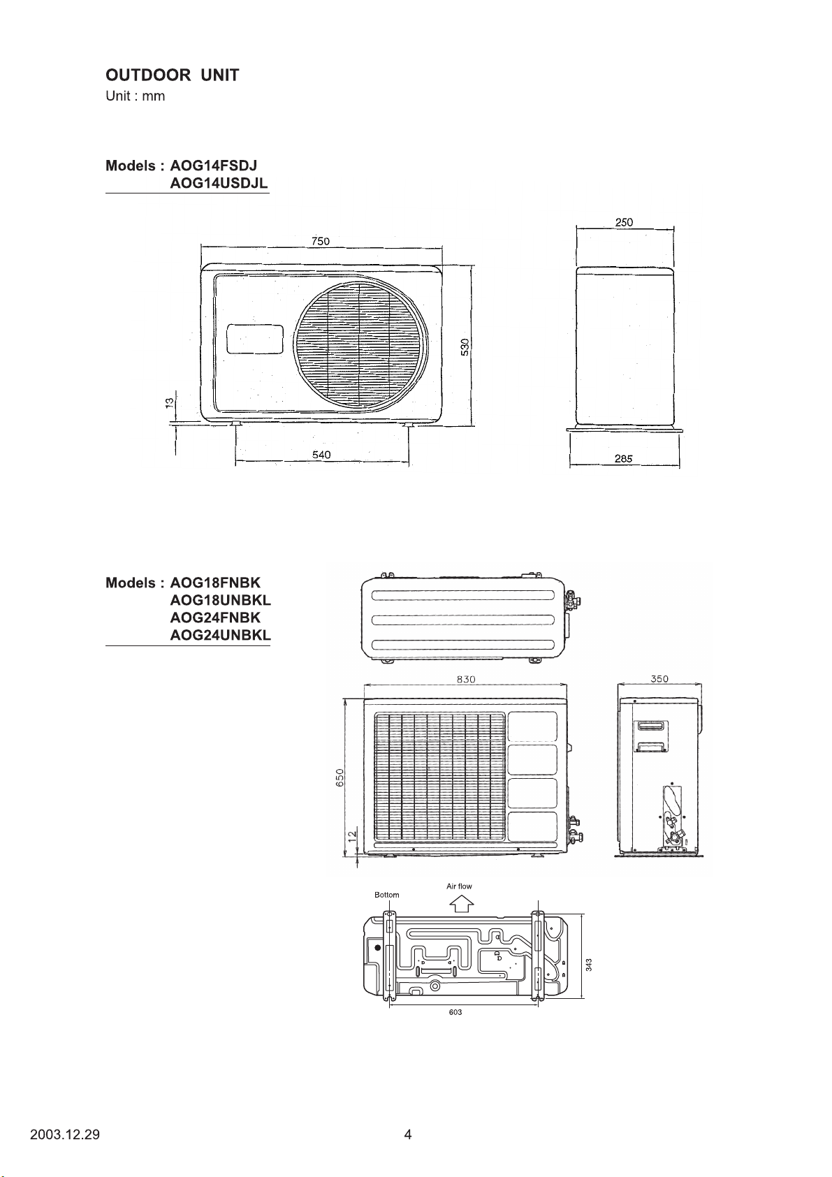
AOG14FSDJ
AOG14USDJL
AOG18FNBK
AOG18UNBKL
AOG24FNBK
AOG24UNBKL
CONTENTS
SPECIFICATIONS
OUTLINE AND DIMENSIONS
REFRIGERANT SYSTEM DIAGRAM
CIRCUIT DIAGRAM
ERROR DISPLAY
PCB CIRCUIT DIAGRAM
DISASSEMBLY ILLUSTRATION (Indoor Unit)
DISASSEMBLY ILLUSTRATION (Outdoor Unit)
PARTS LIST (Indoor Unit)
PARTS LIST (Outdoor Unit)
. . . . . . . . . . . . . . . . . . . . . . . . . . . . . . .
. . . . . . . . . . . . . . . . . . . .
. . . . . . . . . . . . .
. . . . . . . . . . . . . . . . . . . . . . . . . . . . .
. . . . . . . . . . . . . . . . . . . . . . . . . . . . . . .
. . . . . . . . . . . . . . . . . . . . . . .
. . . . . . . . . . . . . . . . . . . . . . . .
. . . . . . . . . . . . . . . . . . . . . .
. . . . .
. . . .
1
3
5
8
12
13
15
22
31
33
Page 2
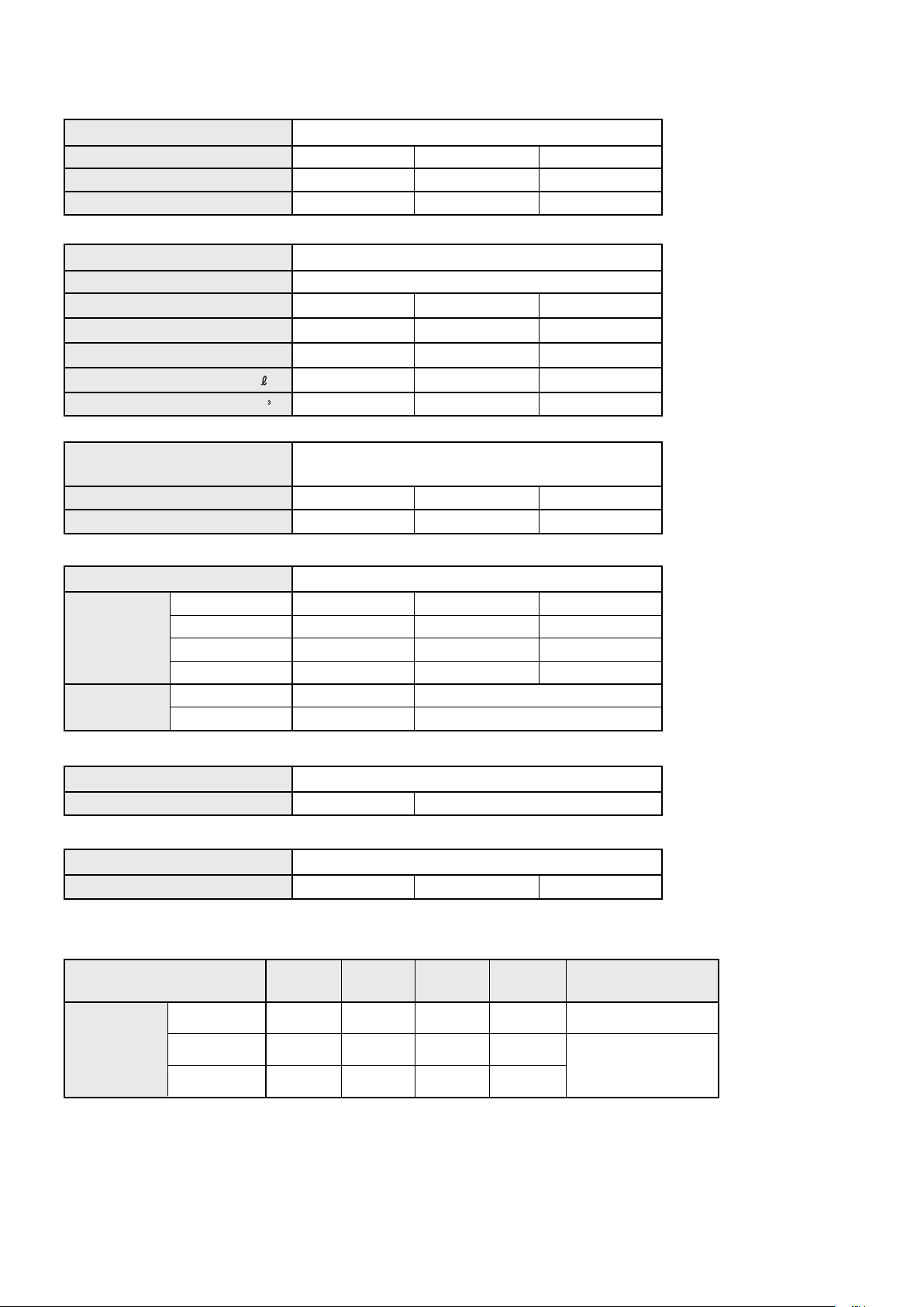
SPECIFICATIONS
TYPE
INDOOR UNIT
OUTDOOR UNIT
COOLING CAPACITY (kW)
ELECTRICAL DATA
POWER SOURCE (V)
FREQUENCY (Hz)
RUNNING CURRENT (A)
INPUT WATTS (kW)
E.E.R. (kW/kW)
MOISTURE REMOVAL ( /hr)
AIR CIRCULATION-Hi (m /hr)
COMPRESSOR
TYPE
CODE
REFRIGERANT R410A (g)
FAN MOTOR
POWER SOURCE (V)
TYPE
INDOOR UNIT
OUTDOOR UNIT
HI-SPEED (r.p.m.)
MED-SPEED (r.p.m.)
LO-SPEED (r.p.m.)
TYPE
HI- SPEED (r.p.m.)
Cool
ABG14FBBJ
AOG14FSDJ
4.20
6.3
1.39
3.02
1.5
640
Hermetic type, Deposit electrode condenser, 2 poles.
Single phase, Induction motor, Rotary
802 360 35(B)
900
MFA-14JTT
850
760
670
MFB-14VTT
740
ABG18FBBJ
AOG18FNBK
5.40
230
50
8.5
1.92
2.81
2.0
780
5KS225DAC
900
230
MFA-18JTT
1,030
890
770
MFB-24JTT
ABG24FBBJ
AOG24FNBK
6.50
11.0
2.45
2.65
2.5
880
5JS290DAA
1,550
MFA-24JTT
1,180
1,040
900
780
DIMENSIONS
INDOOR UNIT H x W x D (mm)
OUTDOOR UNIT
H x W x D (mm)
WEIGHT
INDOOR UNIT
OUTDOOR UNIT
GROSS / NET (kg)
GROSS / NET (kg)
REFRIGERANT CHARGE (R410A)
PIPE LENGTH 7.5 m
ABG14FBBJ
FULL CHARGE
AMOUNT
ABG18FBBJ
ABG24FBBJ
199 x 990 x 655
530 x 750 x 250
37 / 35
(25 ft) (33 ft) (49 ft) (66 ft)
900 g
(31.8oz)
900 g
(31.8oz)
1,550 g
(54.7oz)
10 m 15 m 20 m Additional
938 g
(33.1oz)
950 g
(33.5oz)
1,600 g
(56.4oz)
1,013 g
(35.7oz)
1,050 g
(37.0oz)
1,700 g
(60.0oz)
650 x 830 x 320
37 / 28
51 / 47
1,150 g
(40.6oz)
1,800 g
(63.5oz)
62 / 58
refrigerant
-
15g (0.53oz) / 1m (3.3ft)
(over 7.5m)
20g (0.71oz) / 1m (3.3ft)
(over 7.5m)
12004.02.09
Page 3
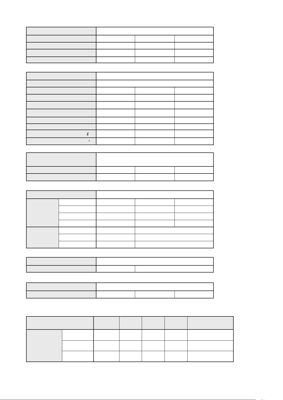
TYPE
INDOOR UNIT
OUTDOOR UNIT
COOLING CAPACITY
HEATING CAPACITY (kW) 6.00
(kW) 5.40
ABG14UBBJ
AOG14USDJL
4.00
4.70
Cool and Heat
ABG18UBBJ
AOG18UNBKL
ELECTRICAL DATA
POWER SOURCE (V)
FREQUENCY (Hz)
RUNNING CURRENT (Cool) (A)
RUNNING CURRENT (Heat) (A)
INPUT WATTS (Cool) (kW)
INPUT WATTS (Heat) (kW)
E.E.R. (Cool) (kW/kW)
E.E.R. (Heat) (kW/kW)
MOISTURE REMOVAL ( /hr)
AIR CIRCULATION-Hi (m /hr) 640
6.3
6.0
1.42
1.35
2.82
3.48
1.5 2.0
COMPRESSOR
TYPE
CODE 802 360 35(B)
REFRIGERANT R410A (g) 1,000
Hermetic type, Deposit electrode condenser, 2 poles.
Single phase, Induction motor, Rotary
5KS225DAC
230
50
8.6
8.3
1.90
1.85
2.84
3.24
780
1,550
ABG24UBBL
AOG24UNBKL
6.50
7.40
10.8
10.3
2.42
2.30
2.69
3.22
2.50
880
5JS290DAA
1,700
FAN MOTOR
POWER SOURCE (V)
TYPE
INDOOR UNIT
OUTDOOR UNIT HI- SPEED (r.p.m.)
HI-SPEED (r.p.m.) 850
MED-SPEED (r.p.m.) 760
LO-SPEED (r.p.m.)
TYPE
LO-SPEED (r.p.m.)
DIMENSIONS
INDOOR UNIT
OUTDOOR UNIT
H x W x D (mm)
H x W x D (mm)
WEIGHT
INDOOR UNIT
OUTDOOR UNIT
GROSS / NET (kg)
GROSS / NET (kg)
REFRIGERANT CHARGE (R410A)
PIPE LENGTH
ABG14UBBJ
FULL CHARGE
AMOUNT
ABG18UBBJ
ABG24UBBJ
230
1,030
890
770670
MFB-24JTBTMFB-14NTT
740
440
199 x 990 x 655
530 x 750 x 250 650 x 830 x 320
37 / 28
37 / 35 56 / 52
7.5 m
(25 ft) (33 ft) (49 ft) (66 ft)
1,000 g
(35.3oz)
1,550 g
(54.7oz)
1,700g
(60.0oz)
10 m 15 m 20 m
1,038 g
(36.6oz)
1,600 g
(54.6oz)
1,800 g
(63.5oz)
1,113 g
(39.3oz)
1,700 g
(60.0oz)
2,000 g
(70.6oz)
780
400
-
1,800 g
(63.5oz)
2,200 g
(77.6oz)
MFA-24JTTMFA-18JTTMFA-14JTT
1,180
1,040
900
63 / 59
Additional
refrigerant
15g (0.53oz) / 1m (3.3ft)
(over 7.5m)
20g (0.71oz) / 1m (3.3ft)
(over 7.5m)
40g (1.42oz) / 1m (3.3ft)
(over 7.5m)
22004.02.09
Page 4
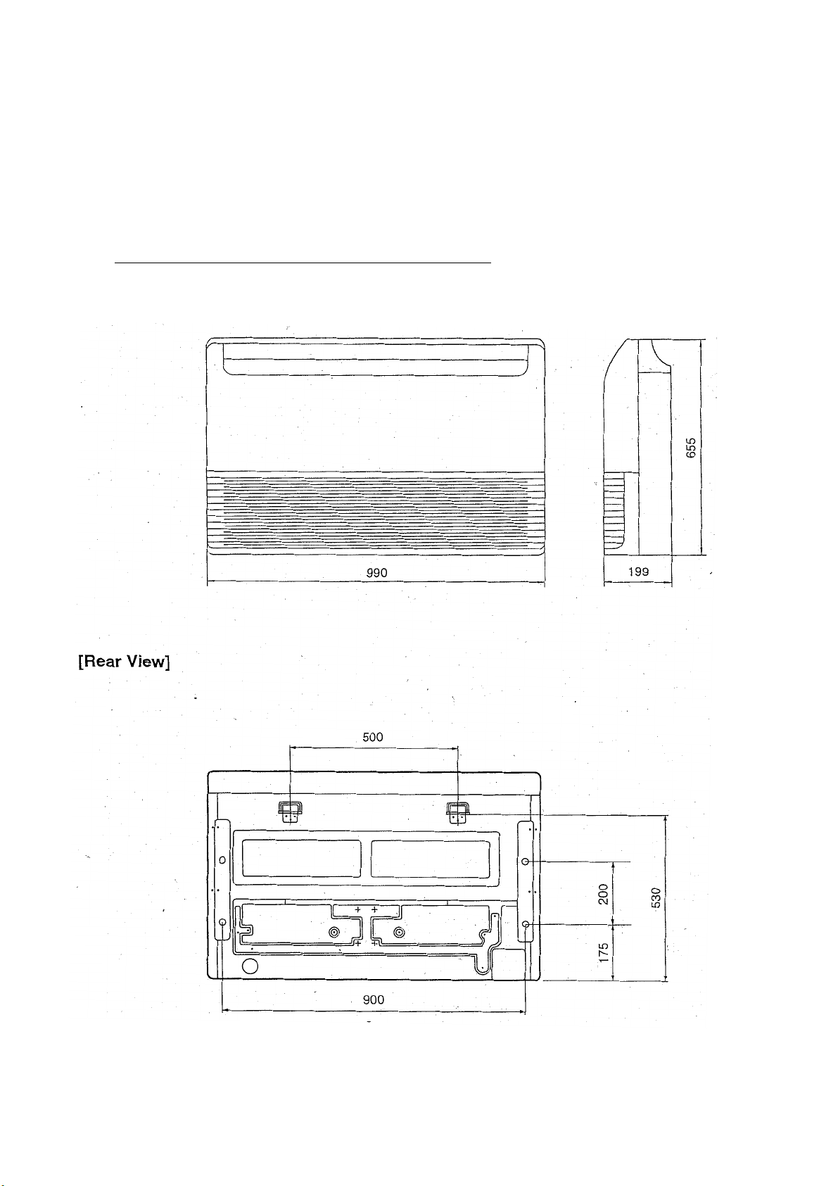
OUTLINE AND DIMENSIONS
Unit : mm
INDOOR UNIT
Models : ABG14FBBJ
ABG14UBBJ
ABG18FBBJ
ABG18UBBJ
ABG24FBBJ
ABG24UBBJ
2003.12.29
3
Page 5
Page 6
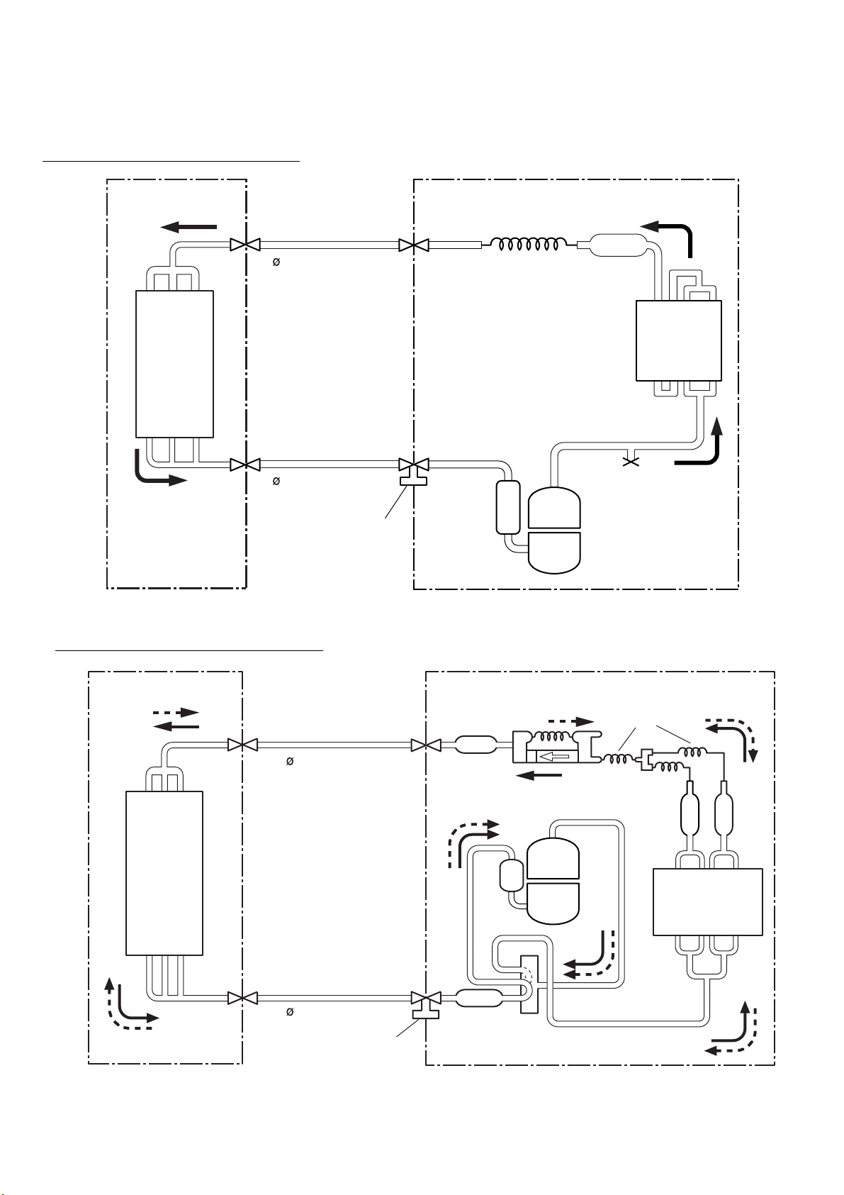
REFRIGERANT SYSTEM DIAGRAM
Models : ABG14FBBJ / AOG14FSDJ
INDOOR UNIT
Evaporator
Refrigerant pipe
6.35 mm (1/4")
Refrigerant pipe
12.7 mm (1/2")
Charging valve
Capillary tube
OUTDOOR UNIT
Strainer
Condenser
Compressor
Models : ABG14UBBJ / AOG14USDJL
INDOOR UNIT
Refrigerant pipe
Distributor
Evaporator
6.35mm(1/4")
Refrigerant pipe
12.7mm(1/2")
Charging valve
Strainer
Muffler
Compressor
4-Way
valve
OUTDOOR UNIT
Capillary
tube
Strainer
Condenser
Strainer
2004.09.08 5
Page 7
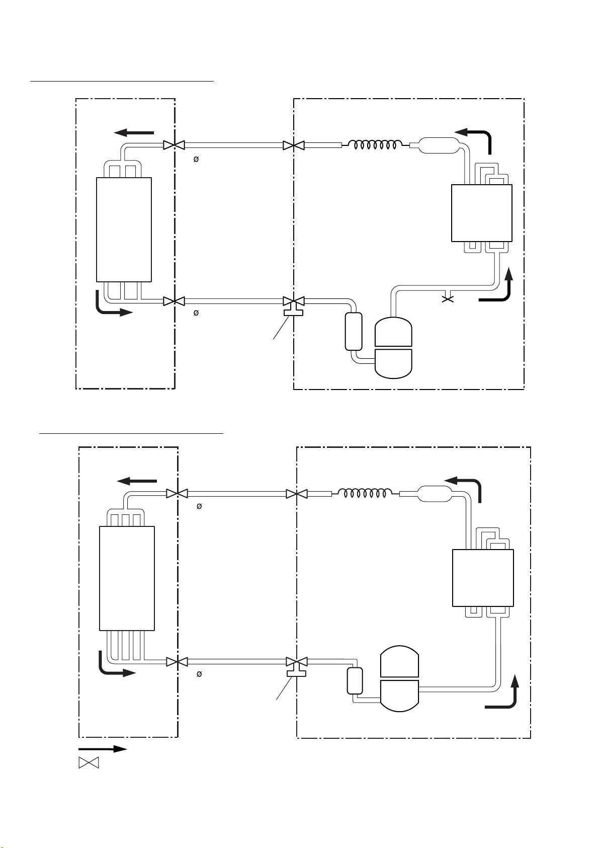
Models : ABG18FBBJ / AOG18FNBK
INDOOR UNIT
Evaporator
Refrigerant pipe
6.35 mm (1/4")
Refrigerant pipe
15.88 mm (5/8")
Charging valve
Capillary tube
OUTDOOR UNIT
Strainer
Condenser
Compressor
Models : ABG24FBBJ / AOG24FNBK
Refrigerant pipe
9.52 mm (3/8")
Evaporator
Refrigerant pipe
15.88 mm (5/8")
Charging valve
Capillary tube
Compressor
OUTDOOR UNITINDOOR UNIT
Strainer
Condenser
Cooling
: Flare coupling
2004.06.09 6
Page 8
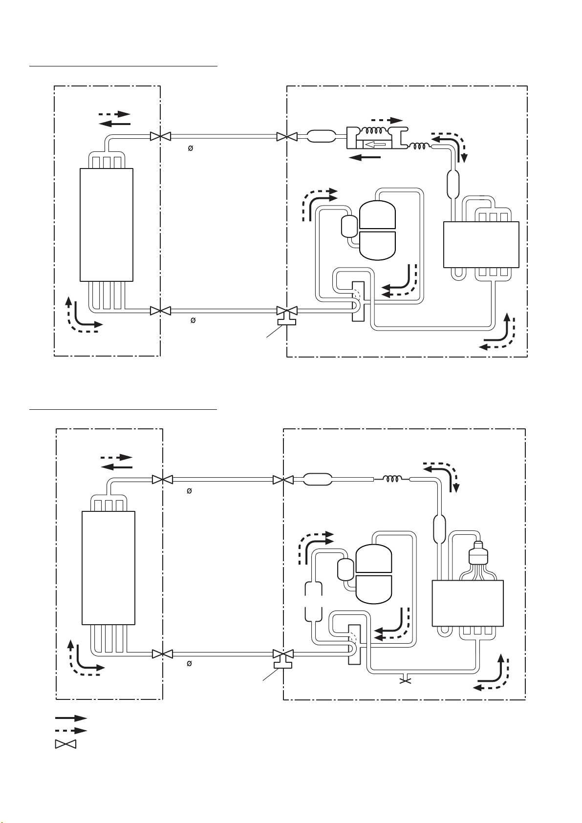
Models:ABG18UBBJ / AOG18UNBKL
Evaporator
Distributor
Refrigerant pipe
15.88mm(5/8")
Refrigerant pipe
9.52mm(3/8")
Cooling
Heating
: Flare coupling
INDOOR UNIT
Strainer
Strainer
Charging valve
4-Way
valve
Compressor
Capillary
tube
OUTDOOR UNIT
Condenser
Accumulator
INDOOR UNIT
Evaporator
Refrigerant pipe
6.35 mm (1/4")
Refrigerant pipe
15.88mm(5/8")
Charging valve
Strainer
4-Way
valve
OUTDOOR UNIT
Capillary
tube
Compressor
Strainer
Condenser
Models : ABG24UBBJ / AOG24UNBKL
2004.06.09 7
Page 9
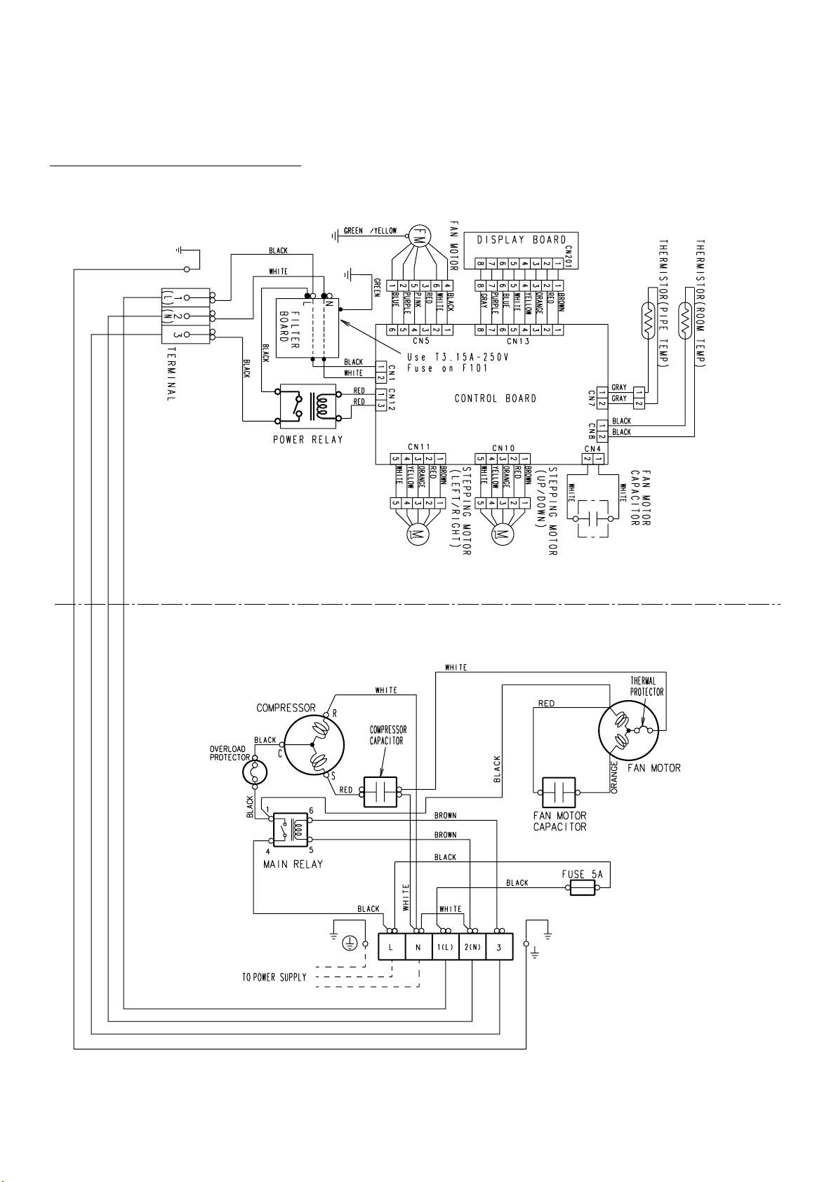
CIRCUIT DIAGRAM
Models
:
ABG14FBBJ / AOG14FSDJ
INDOOR UNIT
OUTDOOR UNIT
2003.01.06 8
Page 10
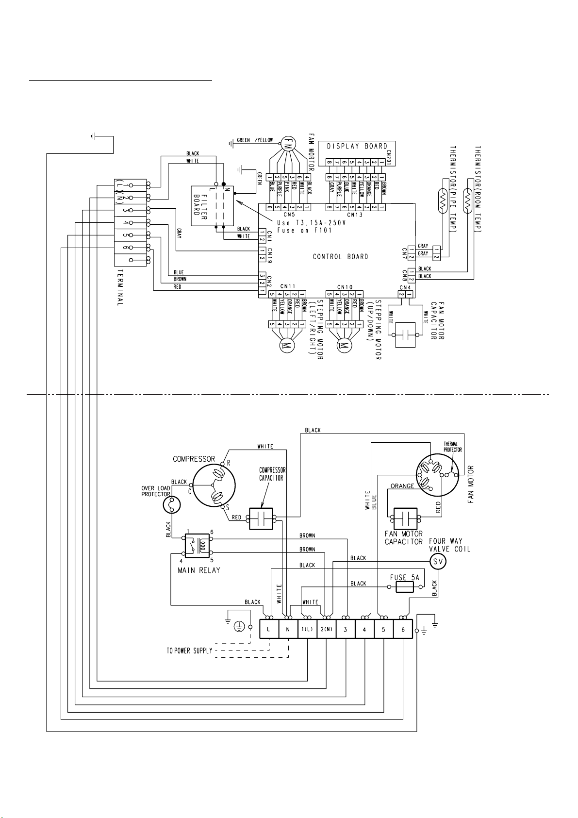
OUTDOOR UNIT
INDOOR UNIT
Models : ABG14UBBJ / AOG14USDJL
2004.02.09
9
Page 11
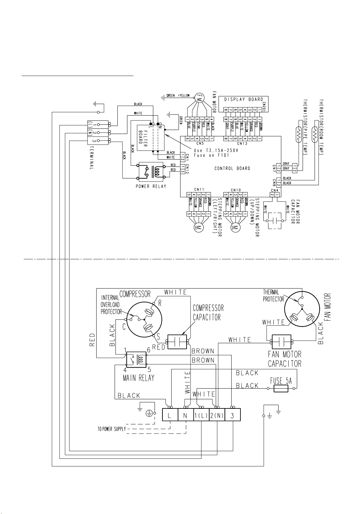
Models
: ABG18FBBJ / AOG18FNBK
ABG24FBBJ / AOG24FNBK
INDOOR UNIT
OUTDOOR UNIT
2003.01.06 10
Page 12
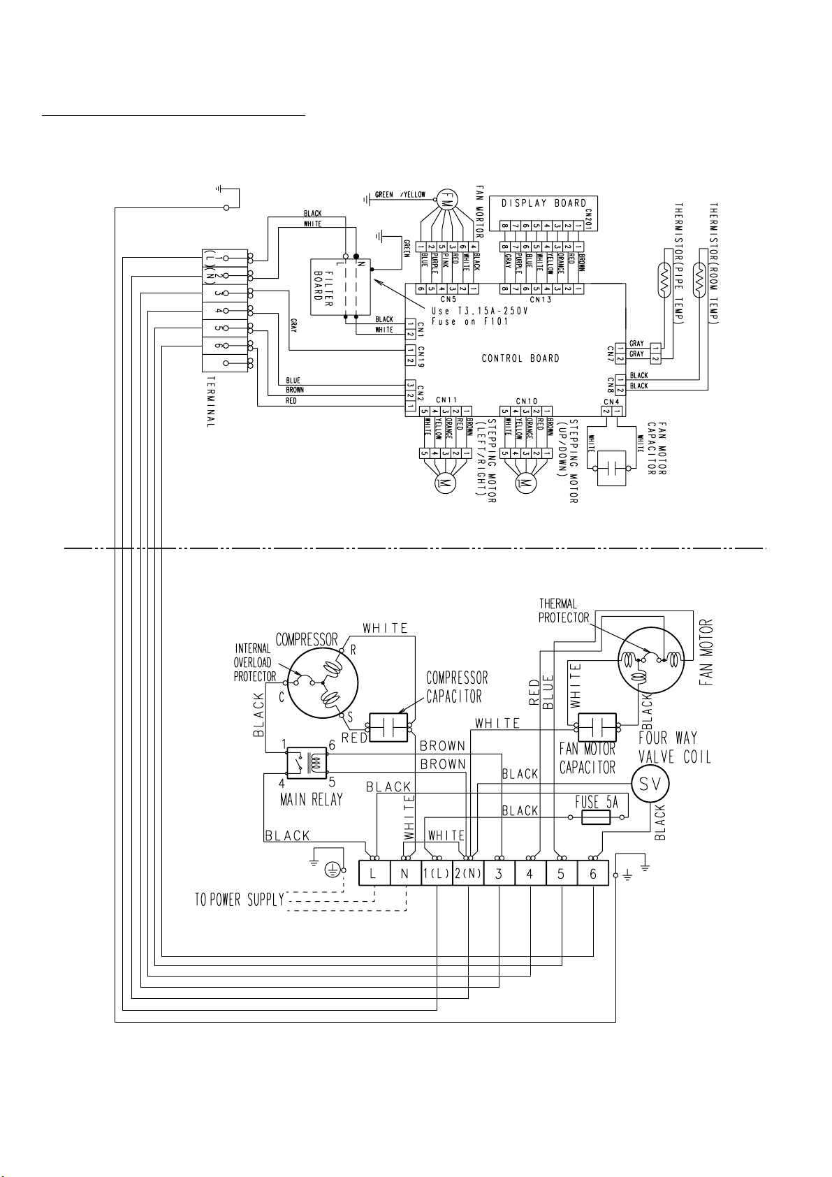
OUTDOOR UNIT
INDOOR UNIT
Models : ABG18UBBJ / AOG18UNBKL
ABG24UBBJ / AOG24UNBKL
2003.01.06
11
Page 13

ERROR DISPLAY
The OPERATION, TIMER and SWING lamps operate as follows according to the error contents.
Fast flashing
:
Slow flashing
:
Error contents
Indoor unit circuit board error
Indoor unit room temperature sensor wire
opened
Indoor unit room temperature sensor wire
short circuited
Indoor unit piping sensor wire opened
Indoor unit piping sensor wire short circuited
Off
:
Error display
OPERATION TIMER SWING
(RED) (GREEN) (ORANGE)
2 times
2 times
3 times
3 times
Indoor unit fan error
6 times
2003.12.29 12
Page 14

INDOOR PRINTED CIRCUIT BOARD
CIRCUIT DIAGRAM
Models :
ABG14FBBJ
ABG18FBBJ
ABG24FBBJ
POWER SOURCE
220 / 240V
50Hz
OUTDOOR UNIT
UL1015 AWG14 BLACK
UL1015 AWG14 BLACK
UL1015 AWG14 WHITE
R1 3.3
<5W>
L
TM101
FH1
W101
N
TM102
W102
UL1015
AWG15
GREEN
FAN CAPACITOR
FAN MOTOR
SA101
<3600V>
F M
YELLOW / GREEN
TERMINAL BOARD
1(L)
2(N)
3
E
D1
D3SB60
C5
100/
450V
BET
F101
FH2
3.15A
<250V>
VA102
470V
W104
W103E101
UL1015 AWG18 BLACK
UL1015 AWG18 WHITE
UL1015 AWG18 WHITE
UL1015 AWG18 WHITE
BLACK
WHITE
RED
PINK
PURPLE
BLUE
UL1015 AWG14 BLACK
R4 330K
<2W>
Q1
2SC4236
R3 100
<1/10W>
Q2
R2 1.5
<2W>
C102
0.22
LF101
ELF20N018A
2SC1815
+
VA101
470V
POWER SUPPLY PCB
EZ-00101HSE-P
CN1 B2P3-VH-B-C BLACK
BLACK
WHITE
RED
PINK
PURPLE
BLUE
UL1015
AWG20
AC I N
POWER RELAY
VF12HU-UL
30A
CN1-1
CN1-2
CN4
B2P3-VH-B-Y
YELLOW
CN4-1
CN4-2
CN5-1
CN5-2
CN5-3 (H)
CN5-4 (M)
CN5-5 (L)
CN5-6 (SL)
CN5
B6P11-VH-B
WHITE
D5
1SR139-600
D10
1SR139-600
C7
0.047
D2
D1FL20U
D3
MTZJ5.1B
R7 330
<1/4W>
C103
0.01
C104
0.01
C6
R5 62K
4700P
<2W>
R6 100
<1/2W>
D4
D1FL20U
C8
100/
+
6.3V
C105
0.022
C106
0.022
K2
G5S-1
UL1430 AWG24
UL1430 AWG24
NO.1
NO.2
NO.3
T1
SWITCHING TRANSFORMER
ZFT29B01
PRIMARY
JM6
C101
0.22
K1
G5S-1
K3
G5S-1
CN9
B5P-SHF-1AA
WHITE
TEST
RED
RED
AUTO RESTART SWITCHING
SW1
DSS803
NOT USED
CUSTOM CODE SWITCHING (R1)
CUSTOM CODE SWITCHING (R2)
D6
D2FL20U
C9
1000
/25V
SECONDARY
SSR1
G3MC-201PL-VD
VA2
470V
5V
R21 - R24
10K <1/10W> x 4
CN9-1
CN9-2
CN9-3
CN9-4
CN9-5
14V
CN12-1
MAGNATIC
CN12-2
RELAY
CN12-3
CN12
B3B-XASK-1-A
WHITE
R39
ROOM TEMPERATURE CORRECTION
( HEATING OPERATION )
ROOM TEMPERATURE CORRECTION
( HEATING OPERATION )
R15 - R17
10K <1/10W> x 3
JM1
JM2
JM3
14V
+
R8 10K
<1/10W>
C54
0.01 <F>
R29 - R32
10K <1/10W> x 4
R11 56K
<1W>
D8
D1F60
IC9
TLP621
<GB>
R13 10K
<1/10W>
5V
R93 - R96
10K <1/10W> x 4
14V
+
-
5V
5V
IC3
7805
I
O
G
5V
5V
R12 1.0K
<1/10W>
C18
0.01
<F>
IC5 (5/7)
uPA2003GR
11
12
K2
13 4
K1
14
K3
15
NC
12 5
NC
13
NC
14
NC
R25 - R28
1.0K <1/10W> x 4
C22 - C25
0.01 <F> x 4
10K <1/10W> x 3
R37R38
R42 1.0K <1/10W>
R41 1.0K <1/10W>
R40 1.0K <1/10W>
R18 1.0K <1/10W>
R19 1.0K <1/10W>
R20 1.0K <1/10W>
R59 10K <1/10W>
R97 10K <1/10W>
R98 10K <1/10W>
R99 10K <1/10W>
5V
C13
C14
0.1
100/
<F>
6.3V
R33 - R36
1.0K <1/10W> x 4
C26 - C29
0.01 <F> x 4
R10 10K
<1/10W>
C17
0.01
Q3
<F>
DTC124EKA
NC
6
5
3
2
4
3
IC6 (3/7)
uPA2003GR
NC
NC
0.01 <F> x 3
CONTROLLERPCB ASSEMBLY ( MAIN PCB )
ABG14FBBJ : EZ-001LWSE-F
ABG18FBBJ : EZ-002YWSE-F
ABG24FBBJ : EZ-002TWSE-F
C19 - C21
0.01 x 3 <F>
C15
+
0.1
<F>
5V
10
8
15
10
16
C10 C12
C47
0.1
<F>
JM10
NC
R9 390
<1/10W>
CR6
0.01
<F>
7
IC5 (1/7)
uPA2003GR
CR1 10K
<1/10W>
IC6 (3/7)
14V
uPA2003GR
9
2
7
1
8
C30
1
P15
2
P16
3
P17
uPD780058BGC
-057-8BT
54
P122
55
P123
66
P05
65
P04
74
VDD0
68
VDD1
75
AVRF0
7
AVRF1
4
AVSS
67
VSS0
33
VSS1
71
I C
72
XT2
P124
56
P125
57
58
P126
59
P127
63
P02
41
P65
42
P66
P64
40
39
P63
38
P62
37
P61
36
P60
52
P120
5149P37
P35
43
P67
44
P30
45
P31
46
P32
48
P34
53
P121
47
P33
19
P40
20
P41
21
P42
X1 X2
70 69
1
I C 1
P10 76
P11 77
P57 35
P56
P50
P27
P26
P25
C32
1000P
<R>
C35
1000P
<R>
34
27
18
17
16
7
5
14V
13
P22
P21
P20
P130
P51
P52
P53
P54
P55
P01
P70
P71
P72
P131
P36
P24
P23
P47
P46
P14
P13
P12
P00
P45
P44
P43
XT1
P03
12
11
5
28
29
30
31
32
62
8
9
10
6
50
15
14
26
25
80
79
78
61
24
23
22
73
64
4
2
R75 10K <1/10W>
R76 10K <1/10W>
R100 10K <1/10W>
R58 10K <1/10W>
CR2 10K <1/10W>
CR3 10K <1/10W>
CR4 10K <1/10W>
JM11
C43
C16
0.01
0.01
<F>
<F>
5V
R55 10K
<1/10W>
60
RESET
C44
0.1
<F>
3
X1 5MHz
2
R44 1.0K
<1/10W>
R46 1.0K
<1/10W>
14V
9
1
10
6
12
9
13
15
1 16
8
IC4 (7/7)
uPA2003GR
C40
0.01
<F>
R50 10K
<1/10W>
R77 - R79
10K <1/10W> x 3
R81 1.0K <1/10W>
R72 1.0K <1/10W>
R71 1.0K <1/10W>
RJ1 1.0K <1/10W>
C49
C31
0.01
0.01
<F>
<F>
R67 1.0K <1/10W>
CR7
0.01
<F>
3
IC8
PST600C
IC5 (1/7)
uPA2003GR
16
11
143
R51 1.0K
<1/10W>
5V
5V
1
2
CR5
1000P
<R>
4
D0
3
D1
2
SK
1
CS
IC7
BR93LC46RF
6 11
IC6 (1/7)
uPA2003GR
C45
0.1
<F>
R43
10K (1%)
<1/10W>
R45
49.9K (1%)
<1/10W>
R53 10K
<1/10W>
R54 47
<1/10W>
5V
8
VCC
7
NC
C39
0.1
6
NC
<F>
5
GND
R56 1.0K
<1/10W>
R80 10K <1/10W>
R69 10K <1/10W>
R70 10K <1/10W>
RJ2 10K <1/10W>
R68 10K
<1/10W>
C34
0.1
<F>
C37
0.1
<F>
R57 1.0K
<1/10W>
B Z
5V
R49 1.0K
<1/10W>
C38
0.01
<F>
5V
R52 10K
<1/10W>
5V
C41
10/
25V
14V
BZ1
PKM13EPY-4000
5V
C1
0.1
<F>
Q4
DTC124EKA
5V
R48
10K
<1/10W>
14V
CN13-1
CN13-2
CN13-3
CN13-4
CN13-8
CN13-5
C42
+
0.01
<F>
CN13-7
CN13-6
CN13
B8B-XASK-1-A
WHITE
5V
CN8
CN7
CN10
B5B-XASK-1-A
WHITE
CN10-1
CN10-2
CN10-3
CN10-4
CN10-5
CN11-1
CN11-2
CN11-3
CN11-4
CN11-5
CN11
B5B-XARK-1-A
RED
BROWN
RED
ORANGE
YELLOW
GRAY
WHITE
PURPLE
BLUE
UL1430 AWG28
B2B-XASK-1-A
CN8-1
CN8-2
B2B-XAKK-1-A
CN7-1
UL1430 AWG24 GRAY
CN7-2
UL1430 AWG24 GRAY
CN14
B4B-XH-AM
WHITE
5V
R47 390
<1/10W>
BROWN
RED
ORANGE
YELLOW
WHITE
BROWN
RED
ORANGE
YELLOW
WHITE
UL1430 AWG28
BROWN
RED
ORANGE
YELLOW
GRAY
WHITE
PURPLE
BLUE
BLACK
BLACK
R201 330 <1/4W>
1
R202 330 <1/4W>
2
R203 330 <1/4W>
3
R204 330 <1/4W>
4
8
5
7
6
CN201
7P-SCN
WHITE
BLACK
CN14-4
CN14-3
CN14-2
JEM-A
CN14-1
BROWN
RED
ORANGE
YELLOW
WHITE
BROWN
RED
ORANGE
YELLOW
WHITE
SW201
MANUAL AUTO
SWITCH
EVQ PEE 04R
INDICATOR PCB
EZ-0964HSE-D
ROOM TEMPERATURE THERMISTOR
GRAY
GRAY
PIPE TEMPERATURE THERMISTOR
HA
LOUVER
M
( UP / DOWN )
LOUVER
M
( RIGHT / LEFT )
5V
C201
0.1
<F>
OPERATE
TIMER
LOUVER
LOUVER
PHA201
SBX1810
-22
D201 SLR-325 <RED>
D202 SLR-325 <GRN>
D203 SLR-325 <ORG>
D204 SLR-325 <ORG>
C202
+
10/
25V
OUT
2004.01.15 13
Page 15

Models :
ABG14UBBJ
ABG18UBBJ
ABG24UBBJ
POWER SOURCE
220 / 240V
50Hz
OUTDOOR UNIT
UL1015 AWG14 BLACK
TM101
W102
UL1015 AWG14 WHITE
FH101
L
N
E101
GREEN
UL1015 AWG16
FAN CAPACITOR
FAN MOTOR
F M
YELLOW / GREEN
TERMINAL
BOARD
1(L)
2(N)
SA101
<3600V>
3
4
5
6
E
R1 3.3
<5W>
F101
3.15A
<BET>
W103
D1
D3SB60
C5
100/
450V
FH102
VA102
470V
W104
UL1015 AWG18
UL1015 AWG18
UL1015 AWG18
BLACK
WHITE
RED
PINK
PURPLE
BLUE
UL1015
AWG20
BLUE
BROWN
GRAY
UL1015 AWG18
MAGNATIC
RELAY
R4 330K
<2W>
Q1
2SC4236
R3 100
<1/10W>
Q2
R2 1.5
<2W>
C102
0.22
2SC1815
LF101
ELF20N018A
+
VA101
470V
POWER SUPPLY PCB
EZ-00210HSE-P
CN1 B2P3-VH-B-C BLACK
BLACK
WHITE
RED
PINK
PURPLE
BLUE
UL1015
AWG20
OUT
CN2-3 HI
CN2-2 LO
CN2-1 4WV
CN2
B3P5-VH-B-R
RED
CN19
B2P3-VH-B-R
RED
CN19-1
CN19-2
AC I N
BLACK
WHITE
WHITE
WHITE
K8
G5NB-1A
DC12V
CR8
TA120033
UL1015 AWG18
RED
C6
4700P
D5
1SR139-600
D10
1SR139-600
C7
0.047
D2
D1FL20U
D3
MTZJ5.1B
R7 330
<1/4W>
C103
0.01
C104
0.01
CN1-1
CN1-2
CN4
B2P3-VH-B-Y YELLOW
CN4-1
CN4-2
CN5-1
CN5-2
CN5-3 H
CN5-4 M
CN5-5 L
CN5-6 SL
CN5
B6P11-VH-B
WHITE
K6
G5S-1
DC12V
K7
G5NB-1A
DC12V
C46 0.22
R90 120
<1/2W>
K2
G5S-1
DC12V
K5
G5NB-1A
DC12V
C4 0.22
R89 120
<1/2W>
R5 62K
<2W>
R6 100
<1/2W>
D4
D1FL20U
C8
100/
6.3V
C105
0.022
C106
0.022
NO.1
NO.2
NO.3
SWITCHING TRANSFORMER
ZFT29B01
PRIMARY
JM6
C101
0.22
K1
G5S-1
DC12V
K3
G5S-1
DC12V
CN9
B5P-SHF-1AA
WHITE
TEST
AUTO RESTART SWITCHING
SW1
DSS803
R15 - R17
NOT USED
CUSTOM CODE SWITCHING (R1)
CUSTOM CODE SWITCHING (R2)
10K <1/10W> x 3
T1
D6
D2FL20U
C9
1000
/25V
SECONDARY
C54
0.01 <F>
SSR1
G3MC-201PL-VD
DC12V
VA2
470V
5V
R21 - R24
10K <1/10W> x 4
CN9-1
CN9-2
CN9-3
CN9-4
CN9-5
10K <1/10W> x 3
R39
ROOM TEMPERATURE CORRECTION
( HEATING OPERATION )
ROOM TEMPERATURE CORRECTION
( HEATING OPERATION )
JM1
JM2
JM3
14V
+
R29 - R32
10K <1/10W> x 4
R11
56K
<1W>
D8
D1F60
IC9
TLP621
<GB>
R13 10K
<1/10W>
5V
+
-
5V
R38
R8 10K
<1/10W>
IC3
7805
IGO
5V
R12 1.0K
<1/10W>
R93 - R96
10K <1/10W> x 4
14V
K 2
K 1
K 3
NC
K 6
K 5
K 7
R25 - R28
1.0K <1/10W> x 4
14V
R37
5V
R18 1.0K <1/10W>
R19 1.0K <1/10W>
R20 1.0K <1/10W>
R59 10K <1/10W>
R97 10K <1/10W>
R98 10K <1/10W>
R99 10K <1/10W>
5V
C13
C14
0.1
100/
<F>
6.3V
5V
R33 - R36
1.0K <1/10W> x 4
C26 - C29
0.01 <F> x 4
R10 10K
<1/10W>
C17
C18
0.01
0.01
<F>
<F>
NC
IC5 (5/7)
uPA2003GR
11
6
12
5
13
4
14
3
15
2
12
5
13
4
14 3
IC6 (3/7)
uPA2003GR
C22 - C25
0.01 <F> x 4
K 8
NC
IC6 (3/7)
uPA2003GR
NC
R42 1.0K <1/10W>
R41 1.0K <1/10W>
R40 1.0K <1/10W>
0.01 <F> x 3
CONTROLLER PCB ASSEMBLY ( MAIN PCB )
ABG14UBBJ : EZ-00312HSE-F
ABG18UBBJ : EZ-00211HSE-F
ABG24UBBJ : EZ-00210HSE-F
P10
P11
P57
P56
P50
P27
P26
P25
P22
P21
P20
P130
P51
P52
P53
P54
P55
P01
P70
P71
P72
P131
P36
P24
P23
P47
P46
P14
P13
P12
P00
P45
P44
P43
XT1
P03
RESET
X2
3
X1 5MHz
76
C32
1000P
<R>
77
C35
1000P
<R>
35
34
27
18
17
16
13
12
11
5
28
29
30
31
32
62
8
9
10
6
50
15
R75 10K <1/10W>
R76 10K <1/10W>
14
26
R100 10K <1/10W>
25
R58 10K <1/10W>
80
CR2 10K <1/10W>
79
CR3 10K <1/10W>
CR4 10K <1/10W>
78
61
24
23
22
73
C43
0.01
<F>
64
R55
10K
<1/10W>
60
C44
0.1
<F>
7 10
5
14V
9
4
2
IC4 (7/7)
uPA2003GR
R50 10K
<1/10W>
R77 - R79
10K <1/10W> x 3
JM11
C16
0.01
<F>
5V
C19 - C21
0.01 x 3
<F>
C15
+
0.1
<F>
5V
R9 390
<1/10W>
Q3
DTC124EKA
10
8
14V
9
15
10
16
8
C10 C30
C12
C47
0.1
<F>
JM10
NC
CR6
0.01
<F>
7
IC5 (1/7)
uPA2003GR
CR1 10K
<1/10W>
2
7
1
1
P15
2
P16
3
P17
uPD780058BGC
-057-8BT
54
P122
55
P123
66
P05
65
P04
74
VDD0
68
VDD1
75
AVRF0
AVRF1
7
4
AVSS
67
VSS0
33
VSS1
71
I C
72
XT2
56
P124
57
P125
58
P126
59
P127
63
P02
41
P65
42
P66
40
P64
39
P63
38
P62
37
P61
36
P60
52
P120
51
P37
49
P35
43
P67
44
P30
45
P31
46
P32
48
P34
P121
53
47
P33
19
P40
20
P41
21
P42
X1
70 69
1
I C 1
2
R44 1.0K
<1/10W>
R46 1.0K
<1/10W>
IC5 (1/7)
14V
uPA2003GR
9
16
1
11
6
12
13
3
14
15
1816
R51 1.0K
C40
<1/10W>
0.01
<F>
5V
R81 1.0K <1/10W>
R72 1.0K <1/10W>
R71 1.0K <1/10W>
RJ1 1.0K <1/10W>
C31
C49
0.01
0.01
<F>
<F>
R67 1.0K <1/10W>
CR7
0.01
5V
<F>
1
3
IC8
2
PST600C
CR5
1000P
<R>
D0
4
3
D1
2
SK
1
CS
IC7
BR93LC46RF
11
6
IC6 (1/7)
uPA2003GR
C45
0.1
<F>
R43
10K (1%)
<1/10W>
R45
49.9K (1%)
<1/10W>
R53
10K
<1/10W>
R54 47
<1/10W>
5V
8
VCC
7
NC
C39
0.1
6
NC
<F>
5
GND
R56 1.0K
<1/10W>
R80 10K <1/10W>
R69 10K <1/10W>
R70 10K <1/10W>
RJ2 10K <1/10W>
R68
10K
<1/10W>
C34
0.1
<F>
C37
0.1
<F>
5V
R57 1.0K
<1/10W>
B Z
5V
C1
0.1
<F>
Q4
DTC124EKA
5V
R49 1.0K
<1/10W>
C38
0.01
14V
<F>
R52
10K
<1/10W>
5V
C41
+
10/
25V
CN13
B8B-XASK-1-A
WHITE
DISPLAY
14V
BZ1
PKM13EPY-4000
5V
R48
10K
<1/10W>
CN13-1
CN13-2
CN13-3
CN13-4
CN13-8
CN13-5
C42
0.01
<F>
CN13-7
CN13-6
5V
CN8
CN7
CN10
B5B-XASK-1-A
WHITE
CN10-1
CN10-2
CN10-3
CN10-4
CN10-5
CN11-1
CN11-2
CN11-3
CN11-4
CN11-5
CN11
B5B-XARK-1-A
RED
BROWN
RED
ORANGE
YELLOW
GRAY
WHITE
PURPLE
BLUE
UL1430 AWG28
B2B-XASK-1-A WHITE
CN8-1
CN8-2
B2B-XAKK-1-A BLACK
UL1430 AWG24
CN7-1
UL1430 AWG24
CN7-2
CN14
B4B-XH-AM
WHITE
5V
R47 390
<1/10W>
BROWN
RED
ORANGE
YELLOW
WHITE
BROWN
RED
ORANGE
YELLOW
WHITE
UL1430 AWG28
BROWN
1
RED
2
ORANGE
3
YELLOW
4
GRAY
8
WHITE
5
PURPLE
7
BLUE
6
ROOM TEMPERATURE THERMISTOR
BLACK
BLACK
GRAY
GRAY
CN14-4
CN14-3
CN14-2
CN14-1
BROWN
RED
ORANGE
YELLOW
WHITE
BROWN
RED
ORANGE
YELLOW
WHITE
R201 330 <1/4W>
R202 330 <1/4W>
R203 330 <1/4W>
R204 330 <1/4W>
GRAY
GRAY
HA
JEM-A
D201 SLR-325 <RED>
D202 SLR-325 <GRN>
D203 SLR-325 <ORG>
D204 SLR-325 <ORG>
SW201
MANUAL AUTO
SWITCH
EVQ PEE 04R
CN201
7P-SCN
INDICATOR PCB
EZ-0964HSE-D
PIPE TEMPERATURE THERMISTOR
LOUVER
M
( UP / DOWN )
LOUVER
M
( RIGHT / LEFT )
5V
OPERATE
TIMER
LOUVER
LOUVER
C201
0.1
C202
+
10/
25V
<F>
PHA201
OUT
SBX1810
-22
2004.01.15 14
Page 16

580
227
422
508
923
509
173
174
365 -2
365 -2
365 -1
653 -2
653 -2
365 -1
870 -1
870 -1
DISASSEMBLY ASSEMBLY
Models : ABG14FBBJ, ABG14UBBJ
ABG18FBBJ, ABG18UBBJ
ABG24FBBJ, ABG24UBBJ
240
2003.01.05 15
743
Page 17

439
160
418
470
764
577
127
124
124
552
235
553
138
187
68
108
68
578
870 -2
588 -2
588 -1
184 -1
196 -1
574 -2
574 -1
2003.01.05 16
Page 18

755
581
56
164
109
338
67
56
126
653 -1
2003.01.05 17
Page 19

416
417
385
868
771
488
472
473
443
8-1
2003.01.05 18
Page 20

Models : ABG14FBBJ
ABG14UBBJ
ABG18FBBJ
Models : ABG18UBBJ
ABG24FBBJ
ABG24UBBJ
800
790
810
800
790
2004.02.10 19
Page 21

514
34
236
187
815
381
422
982
628
381
625
195
223
628
689
210
211
234
36- 2
824 -3
187 -1
731 -2
629 -1
2003.01.05 20
Page 22

876 -2
684
503
408
520
555
554
558
876 -1
521
505
505
500
505
361 -2
407
361 -2
361 -2
502
361 -3
69
361 -3
69
505
361 -2
361 -3
506
69
320
361
69
321
2003.01.05 21
Page 23

Models : AOG14FSDJ
AOG14USDJL
5
373
734
527
2
98
745
9
987
7
164
4
39
42
138
12
16
824-4
218-3
344
343
34
38
32-2
37
823-2
982-2
982-1
815
423
272
105
13
14
420
2004.02.10 22
Page 24

Models : AOG14FSDJ
AOG14USDJL
2004.09.08 23
Page 25

Model : AOG14FSDJ
18
20
456
272
420
Model : AOG14USDJL
18
329
259
20
2004.02.09 24
420
272
Page 26

Page 27

Page 28

Page 29

Page 30

Page 31

Page 32

PARTS LIST
INDOOR UNIT
Ref.
No.
8-1 Air Filter 9358567029 9358567029 9358567029 9358567029 9358567029 9358567029
34 Capacitor (Fan Motor) 2.3µF/450V ----- -- -- ---- --- -- 9703306044 9703306044 9703306044 9703306044
34 Capacitor (Fan Motor) 1.6µF/400V 9704305039 9704305039 ---- --- -- ---- -- -- - ----- --- - ----- -- -36-2 Cord Holder Metal 9356362008 9356362008 9356362008 9356362008 9356362008 9356362008
56 Sirocco Fan Assy 9385258006 9385258006 9385258006 9385258006 9385258006 9385258006
67 R ubber (Vibration-proof) 9385102002 9385102002 9385102002 9385102002 9385102002 9385102002
69 Louver 9358561010 9358561010 9358561010 9358561010 9358561010 9358561010
68 Cap, Plastic 9358563007 9358563007 9358563007 9358563007 9358563007 9358563007
108 Base Assy 9359061014 9359061014 9359061014 9359061014 9359061014 9359061014
109 Casing, Plastic 9358543009 9358543009 9358543009 9358543009 9358543009 9358543009
124 Dew Proof Plate 9359196006 9359196006 9359196006 9359196006 9359196006 9359196006
126 Motor Fixing Table Ass y 9358591000 9358591000 9358591000 9358591000 9358591000 9358591000
127 Drain Hose Assy 9359242000 9359242000 9359242000 9359242000 9359242000 9359242000
138 Separate Wall-A 9358584002
146 Evaporator Ass y KB07 ---- --- -- ---- -- -- - ----- --- 146 Evaporator Ass y KB45 93625130299362513029 ---- --- -- ---- -- -- 160 Drain Pan Ass y 9358568002 9358568002 9358568002 9358568002 9358568002 9358568002
164 Fan Motor Assy-IN MFA-24JTT -- -- --- -- ---- -- -- - ------ -- - ----- -- -- 9601527015 9601527015
164 Fan Motor Assy-IN MFA-18JTT -- -- --- -- ---- -- -- - 9601527022 9601527022 ------ -- - ----- -- -164 Fan Motor Assy-IN MFA-14JTT 9601527039 9601527039 ---- -- -- - ----- --- - ----- -- -- ---- --- --
173 Hanger Bracket-L 9358596005 9358596005 9358596005 9358596005 9358596005 9358596005
174 Hanger Bracket-R 9358595008 9358595008 9358595008 9358595008 9358595008 9358595008
184-1 Thermistor Spring-A 313728262708 313728262708 313728262708 313728262708 313728262708 313728262708
187 Clamp No. 1219 313361271706 313361271706 313361271706 313361271706 313361271706 313361271706
187-1 Clip (Cable) 9352715006 9352715006 9352715006 9352715006 9352715006 9352715006
195 Clamp SKB-100 313361275805 313361275805 313361275805 313361275805 313361275805 313361275805
196-1 Clamp SKB-3M 312300787605 312300787605 312300787605 312300787605 312300787605 312300787605
210 Main Relay 9353611017 9353611017 9353611017
211 Cushion Rubber 313806328306 313806328306 313806328306
223 Control Box 9358600016 9358600016 9358600016 9358600016 9358600016 9358600016
Description
ABG14FBBJ
9358584002 9358584002 9358584002 9358584002 9358584002
9362513029
---- --- --
---- --- --
When you order parts, please make a photocopy of this page
and fill the number of the parts in the "Order" column.
Part No.
ABG24UBBJABG14UBBJ ABG18FBBJ ABG18UBBJ ABG24FBBJ
---- --- --
---- --- --
---- --- --
93625130369362513036 9362513036
---- --- --
---- --- --
Ord.
Q'ty
227 Badge (ABG Model) 9357914008 9357914008 9357914008 9357914008 9357914008 9357914008
234 Thermistor Assy-R oom 9703299087 9703299087 9703299087 9703299087 9703299087 9703299087
235 Thermistor Assy-Pipe 9900022020 9900022020 9900022020 9900022020 9900022020 9900022020
236 Controller P CB Assy
240 Remote Control Unit AR-J W1 --- -- --- - 9371190013 - -- -- --- - 9371190013 - --- -- -- - 9371190013
240 Remote Control Unit AR-J W2 9371190020 ----- --- 320 Flap ( Upper)-G (ABG Model) 9358539019 9358539019 9358539019 9358539019 9358539019 9358539019
321 Flap ( Lower) 9358541012 9358541012 9358541012 9358541012 9358541012 9358541012
338 Motor Fixture 9358594001 9358594001 9358594001 9358594001 9358594001 9358594001
361 Bushing 9357942001 9357942001 9357942001 9357942001 9357942001 9357942001
361-2 Bushing-B, Plastic 9358554005 9358554005 9358554005 9358554005 9358554005 9358554005
361-3 Bushing-C, Plastic 9358553008 9358553008 9358553008 9358553008 9358553008 9358553008
365-1 Special Screw 9359092001 9359092001 9359092001 9359092001 9359092001 9359092001
365-2 Special Screw 9359091004 9359091004 9359091004 9359091004 9359091004 9359091004
381 Locking S pacer, KGLS-4S 313209391506 313209391506 313209391506 313209391506 313209391506 313209391506
385 Indicator PCB Assy EZ-0964HSE-D 9701873012 9701873012 9701873012 9701873012 9701873012 9701873012
407 Motor R od 9358560006 9358560006 9358560006 9358560006 9358560006 9358560006
408 Louver Link 9358556009 9358556009 9358556009 9358556009 9358556009 9358556009
416 Insulation (Panel)-A 9358574003 9358574003 9358574003 9358574003 9358574003 9358574003
417 Insulation (Panel)-B 9358914007 9358914007 9358914007 9358914007 9358914007 9358914007
418 Insulation (Flap Base) 9358572009 9358572009 9358572009 9358572009 9358572009 9358572009
9704557094
(EZ-001LWSE-C)
9704557551
(EZ-00100HSE-C)
9704557216
(EZ-002YWSE-C)
9371190020 - -- -- --- - 9371190020 - -- --- -- -
9704557551
(EZ-0021HSE-C)
9704557131
(EZ-002TWSE-C)
9704557148
(EZ-00210HSE-C)
2003.01.05 31
Page 33

INDOOR UNIT (Continued)
When you order parts, please make a photocopy of this page
and fill the number of the parts in the "Order" column.
Ref.
Description
No.
422 Clamp NK-10N 9359183006 9359183006 9359183006 9359183006 9359183006 9359183006
439 Drain Pan Wire 9358598009 9358598009 9358598009 9358598009 9358598009 9358598009
443 Arm Bracket 9359281009 9359281009 9359281009 9359281009 9359281009 9359281009
470 Separate Wall-B 9358585009 9358585009 9358585009 9358585009 9358585009 9358585009
472 Grille Support 9358602003 9358602003 9358602003 9358602003 9358602003 9358602003
473 Filter Bracket 9358607008 9358607008 9358607008 9358607008 9358607008 9358607008
488 Grill-G 9358533017 9358533017 9358533017 9358533017 9358533017 9358533017
500 Protect Cover 9358564004 9358564004 9358564004 9358564004 9358564004 9358564004
502 Support S tay 9358599006 9358599006 9358599006 9358599006 9358599006 9358599006
503 Louver Shaft 9358557006 9358557006 9358557006 9358557006 9358557006 9358557006
505 Louver Stopper 9358555002 9358555002 9358555002 9358555002 9358555002 9358555002
506 Louver Rod 9358559000 9358559000 9358559000 9358559000 9358559000 9358559000
508 Cosmetic Panel-R 9358535011 9358535011 9358535011 9358535011 9358535011 9358535011
509 Cosmetic Panel-L 9358536018 9358536018 9358536018 9358536018 9358536018 9358536018
514 Control Box Cover 9359097006 9359097006 9359097006 9359097006 9359097006 9359097006
520 Flap Base 9358537015 9358537015 9358537015 9358537015 9358537015 9358537015
521 Louver Link Cover 9358558003 9358558003 9358558003 9358558003 9358558003 9358558003
552 Insulation (Eva.)-R 9358575000 9358575000 9358575000 9358575000 9358575000 9358575000
553 Insulation (Eva.)-L 9358857007 9358857007 9358857007 9358857007 9358857007 9358857007
554 Flap Link-Upper ( Step Motor-V) 9358551004 9358551004 9358551004 9358551004 9358551004 9358551004
555 Flap Link-Lower (S tep Motor-V) 9358552001 9358552001 9358552001 9358552001 9358552001 9358552001
558 Motor Rod-A ( Step Motor-V) 9358550007 9358550007 9358550007 9358550007 9358550007 9358550007
574-1 Evaporator Fixture-R (Bracket) 9358589007 9358589007 9358589007 9358589007 9358589007 9358589007
574-2 Evaporator Fixture-L (Bracket) 9358590003 9358590003 9358590003 9358590003 9358590003 9358590003
577 Catch TL-119 9359096009 9359096009 9359096009 9359096009 9359096009 9359096009
578 Base Bracket (R einforcement Metal) 9358586006 9358586006 9358586006 9358586006 9358586006 9358586006
580 Top Cover 9358534014 9358534014 9358534014 9358534014 9358534014 9358534014
581 Protector, Metal (Fan Motor) 9359282006 9359282006 9359282006 9359282006 9359282006 9359282006
588-1 Evaporator Bracket-R 9358587003 9358587003 9358587003 9358587003 9358587003 9358587003
588-2 Evaporator Bracket-L 9358588000 9358588000 9358588000 9358588000 9358588000 9358588000
Part No.
ABG24UBBJABG14UBBJ ABG18FBBJ ABG18UBBJ ABG24FBBJABG14FBBJ
Ord.
Q'ty
625 Cord Bushing KR-51 9359240006 9359240006 9359240006 9359240006 9359240006 9359240006
628 Locking Spacer-B 313005446558 313005446558 313005446558 313005446558 313005446558 313005446558
629-1 EMI Filter 0400247074 0400247074 0400247074 0400247074 0400247074 0400247074
652-1 Thermistor Holder Pipe 313806262805 313806262805 313806262805 313806262805 313806262805 313806262805
653-1 Bolt (Fan Motor Fixing) 0700156014 0700156014 0700156014 0700156014 0700156014 0700156014
653-2 Bolt 0700190018 0700190018 0700190018 0700190018 0700190018 0700190018
684 Motor Base 9358562000 9358562000 9358562000 9358562000 9358562000 9358562000
689 Screw, Grip Tapping 9357837000 9357837000 9357837000
731-2 Holder (Guide R ail) 0600241018 0600241018 0600241018 0600241018 0600241018 0600241018
743 Remote Control Unit Holder 9305642014 9305642014 9305642014 9305642014 9305642014 9305642014
755 Casing Cover 9358544006 9358544006 9358544006 9358544006 9358544006 9358544006
764 Drain Cap 9358746004 9358746004 9358746004 9358746004 9358746004 9358746004
771 Panel Assy 9359076025
735
790
800
810
815-1 Terminal 3P ------- -- -- -- -- --- - -- -- --- - -- -- --- -- - -- --- -- 815 Terminal 7P ------ -- -
824-3 Fuse BET3.15A - 250V 0600222512 0600222512 0600222512 0600222512 0600222512 0600222512
868 PCB Holder 9358547007 9358547007 9358547007 9358547007 9358547007 9358547007
870-1 Arm 9358565001 9358565001 9358565001 9358565001 9358565001 9358565001
870-2 Center Arm 9359280002 9359280002 9359280002 9359280002 9359280002 9359280002
875 Power Supply PCB Assy
876-1 Step Motor-H 9359106012 9359106012 9359106012 9359106012 9359106012 9359106012
876-2 Step Motor-V 9359105015 9359105015 9359105015 9359105015 9359105015 9359105015
923 Control Box Bracket 9358717004 9358717004 9358717004 9358717004 9358717004 9358717004
982 Cord Clamp 9357864006 9357864006 ------- -- 9357886008 ------ -- - 9357886008
SN+4016 ZNY w/Grip
DISTR IBUTOR AS 9373034018 9373034018 9373034018 9373034032 9373034025 9373034025
COUPR ING PIPE ASSY 9373038061 9373038061 9373038016 9373038023 9373038023 9373038023
BYPASS PIPE ASS Y 9373032014 9373032014 9373032014 9373032021 9373032021 9373032021
BYPASS PIPE B 9371346038 9371346038 9371346038
---- --- -- - -- --- -- - -- --- -- --
9900203016
9704561022
(EZ-00101HSE-P)
---- --- -- ---- --- --
9359076025 9359076025 9359076025 9359076025 9359076025
9358660102 --- --- -- - 9358660102 ------- -- 9358660102
9704561022
(EZ-00101HSE-P)
9704561022
(EZ-00101HSE-P)
9704561077
(EZ-00210HSE-P)
9704561022
(EZ-00101HSE-P)
---- --- --
9704561077
(EZ-00210HSE-P)
OPTIONAL PARTS FOR INDOOR UNIT
Ref. Ord.
No.
772 Joint Pipe-A 9302812021
Description
Part No.
Q'ty
2004.02.10 32
Page 34

OUTDOOR UNIT
Ref.
No.
2 Guard (Fan) 9304109006 9304109006
4 Emblem-Rear 9372171011 9372171011
5 Cabinet Painted 9302936017 9302936017
7 Cover (Switch) Assy 9357970004 9357970004
9 Panel (Cabinet Rear) Painted 9303744017 9303744017
12 Base Assy, Painted 9310889114 9310889114
13 3-Way Valve Assy 9372205105 9372205105
14 2-Way Valve Assy 9372204030 9372204030
15 Strainer Assy 9366602019 9366602019
16 Condenser Assy 9373131045 9373131014
32-1 Control Box Metal-A 9355843003 9355843003
34 Capacitor, Plastic DS401165NPQA 9900231026 9900231026
37 Capacitor, Plastic DS401306CCNA ---- ---37 Capacitor, Plastic DS401356CCNA 9704436139 9704436139
38 Clamp Metal (Capacitor) 313468061808 313468061808
39 Propeller Fan 9351589011 9351589011
41 Motor, Induction MFB-14VTT 9601113010 ---41 Motor, Induction MFB-14NTT ---- 9601113096
42 Bracket (Motor) 313166243804 313166243804
51 Special Nut M5 313199233602 313199233602
55 Special Nut M8 9355091008 9355091008
98 Ring Fan 313166296109 313166296109
105 Compressor Assy 9373010043 9373010043
107 Rubber Seat (For Comp)-A 9351813017 9351813017
109 Terminal Cover 9351920012 9351920012
128-1 Rubber (Discharge Pipe) 313155086308 313185159802
138 Separator Sub Assy 9303729014 ---178-2 Capillary Holder Rubber 313394274808 ---199-1 BR Sheet 9363708035 ---200-1 BR Sheet-B 9351990022 9351990022
Description
AOG14FSDJ AOG14USDJL
Part No.
Ord.
Q' ty
210 Relay 9900074012 9900074012
213 S-INS. B 313584258005 313584258005
230 OCR Assy 9373129011 9373129011
343 Solenoid ---- 9900165017
344 4-Way Valve ---- 9970036019
373 Grip 313166178700 313166178700
412 Cover Gasket 9351921019 9351921019
420 Capillary Assy 9372197189 9372197110
423 Noise Insulation-F 9350944019 9350944019
527 Protective Net 9355444002 9355444002
734 Panel (Top) Painted 9302937014 9302937014
745 RFM (Motor) 313166036308 313166036308
764 Drain Cap ---- 313166024302
765 Drain Pipe (I-Type) ---- 9301102000
766 Drain Packing ---- 9301143003
815 Terminal-8P ---- 9900203047
815-3 Terminal-5P 9900203023 ---982-1 Clamp (Cord) 9356857009 9356857009
982-2 Clamp (Cord)-B 9356858006 9356858006
--- Special Washer 301801155013 301801155013
--- Muffler ---- 9372369029
When you order parts, please make a photocopy of this page
and fill the number of the parts in the "Order" column.
2004.09.08 33
Page 35

OUTDOOR UNIT (Continued)
When you order parts, please make a photocopy of this page
and fill the number of the parts in the "Order" column.
Ref.
No.
2 Fan Guard
4 Emblem-Rear
5 Front Panel Ptd
7 Connector Cover (Cabinet)
8 Wire Assy ( Comp)
9 S ide Panel R Ptd
12 Base Assy, Ptd
13 3-Way Valve Assy
14 2-Way Valve Assy
16 Condenser Assy
26 Compressor Cover
29 Separate Wall
32 Control Box
34 Capacitor, Plastic
37 Running Capacitor
38 Capacitor Clamp Metal
39 Propeller Fan Assy
41 Motor Induct
45-1 Motor Bracket
45-2 Motor Bracket-Top
45-3 Motor Bracket Center
45-4 Motor Bracket Bottom
46 Compressor Assy
47-1 Rubber (Discharge Pipe)
51 Special Nut M5
55 Special Nut M8
64 Side Panel L Ptd
69-3 Bolt, Hex. S ocket
85 Valve Plate Ptd
107 Rubber Seat-A
Description
Part No.
AOG18FNBK AOG24FNBK
9371187013
9372171011
9371924014
9366398004
9372334010
9371927015
9371920054
9372205013
9372204016
9372181041
9372327012
9371933016
9371935010
9900130022
9703107122
9351770013
9366378013
9601671022
9371929019
9371931012
9371930015
9371932019
9372558027
313194159807
9300301015
9355091008
9371926018
301210060360
9371928012
9351049010
9371187013
9372171011
9371924014
9366398004
9372334010
9371927015
9371920016
9372205013
9372204023
9372181027
9372327012
9371933016
9371935010
9900130022
9703107023
313791061807
9366378013
9601671022
9371929019
9371931012
9371930015
9371932019
9372558010
313194159807
9300301015
9355091008
9371926018
301210060360
9371928012
9351049010
Ord.
Q'ty
Ref.
No.
2 Fan Guard
4 Emblem-Rear
5 Front Panel Ptd
7 Connector Cover ( Cabinet)
8 Wire Assy (Comp)
9 Side Panel R Ptd
12 Base Assy, Ptd
13 3-Way Valve Assy
14 2-Way Valve Assy
16 Condenser Assy
26 Compress or Cover A
29 Separate Wall
32 Control Box
34 Capacitor, Plastic
37 Running Capacitor
38 Capacitor Clamp Metal
39 Propeller Fan Assy
41 Motor Induct
45-1 Motor Bracket
45-2 Motor Bracket-Top
45-3 Motor Bracket Ctr
45-4 Motor Bracket Bottom
46 Compress or Assy
51 Special Nut M5
55 Special Nut M8
64 Side Panel L Ptd
69-3 Bolt, Hex. Socket
85 Valve Plate Ptd
107 R ubber Seat-A
109 Teminal Cover (Comp)
Description
Part No.
AOG18UNBKL AOG24UNBKL
9371187013
9372171011
9371924014
9366398004
9372334010
9371927015
9371920054
9372205013
9372204016
9372181034
9372327012
9371933016
9371935010
9900130022
9703107122
9351770013
9366378013
9601671015
9371929019
9371931012
9371930015
9371932019
9372558027
9300301015
9355091008
9371926018
301210060360
9371928012
9351049010
9371511016
9371187013
9372171011
9371924014
9366398004
9372334010
9371927015
9371920016
9372205013
9372204023
9372181010
9372327012
9371933016
9371935010
9900130022
9703107023
313791061807
9366378013
9601671015
9371929019
9371931012
9371930015
9371932019
9372558010
9300301015
9355091008
9371926018
301210060360
9371928012
9351049010
9371511016
Ord.
Q'ty
109 Termminal Cover (Comp)
187 Clip (Cable)
218-3 Relay
272 Strainer
412 Cover Gasket (Comp.)
527 Protectiive Net
734 Top Plate
735-3 Capillary Assy
754 Terminal Gask. Washer
815 Terminal-5P
823-3 Fuse Holder
824-4 Fuse
982-1 Cord Clamp-A
982-2 Cord Clamp-B
9371511016
9352715006
9900074012
9369287008
9371512013
9371934013
9371925011
9372197066
9351053017
9356497021
0500063024
0600222529
9359822011
9359823018
9371511016
9352715006
9900074012
9369287008
9371512013
9371934013
9371925011
9372197059
9351053017
9356497021
0500063024
0600222529
9359822011
9359823018
187 Clip (Cable)
199 Br Sheet
218-3 R elay
259 Muffler
271 4-Way Valve Rubber
272 S trainer
333 Accumulator
343 S olenoid
344 4-Way Valve
361 Accum Support Assy -----
412 Cover Gasket (Comp.)
527 P rotectiive Net
734 Top Panel
735-3 Capillary Assy
754 Terminal Gask. Washer
815-3 Terminal-5P
823-2 Fuse Holder
824-4 Fuse
982-1 Cord Clamp-A
982-2 Cord Clamp-B
9352715006
9363708059
9900074012
9372369012
313728251908
9369287008
----9900165017
9970036019
9371512013 9371512013
9371934013
9371925011
9372197042
9351053017
9358660119
0500063024
0600222529
9359822011
9359823018
9352715006
-----
9900074012
----313728251908
9369287008
9368391003
9900165017
9900163013
9372252017
9371934013
9371925011
9372197028
9351053017
9358660119
0500063024
0600222529
9359822011
9359823018
2003.01.05 34
Page 36

STANDARD ACCESSORIES
The following installation parts are furnished. Use them as required.
INDOOR UNIT ACCESSORIES
Name and Shape
Cover plate (left)
Q'ty
1
Application
9358536018 9359242000
Name and Shape
Drain hose
Q'ty
1
Application
Cover plate (right)
Tapping screw ( 4x10)
Installation template
Bracket (left)
Bracket (right)
Anchor bolt (M12)
Special nut
Spring washer
Wall bracket
Tapping screw ( 4x20)
1
2
1
1
1
4
4
4
2
9358535011
301171164104
For positioning the indoor
unit
For under ceiling type
9359107002
For suspending the indoor
unit from ceiling
9358596005
9358595008
313806339400
301821112213
For suspending the indoor
unit on the wall.
9358597002
For fixing the wall bracket.
Insulation (drain hose)
VT wire
Remote control unit
Battery (penlight)
Remote control unit holder
Tapping screw ( 3x12)
Adhesive type 70 x 230
1
For fixing the drain hose
1
L 280 mm
Use for air conditioner
operation
1
2
1
2
(for cooling model)
(for cooling & heating model)
For remote control unit
Use as remote control unit
holder
For remote control unit
holder installation
OUTDOOR UNIT ACCESSORIES
Name and Shape
Drain pipe
Drain cap
Q'ty
1
For outdoor unit drain piping
work
[Heat & Cool model
(Reverse cycle) only]
2
9359225003
313806350303
9371190020
9371190013
0600185534
9305642014
301141533125
Application
Coupler heat insulator
(large)
Coupler heat insulator
(small)
Nylon fastener
6
1
1
1
301141164200
For indoor side pipe joint
(Large pipe)
9350716012
For indoor side pipe joint
(Small pipe)
313209328104
For fixing the drain hose
312300787605
2004.02.10 35
OPTIONAL PARTS FOR INDOOR UNIT
Name and Shape Part No. Application
Joint pipe-A
9302812021
For indoor side pipe joint
Page 37

0401G2479
 Loading...