

Page 1
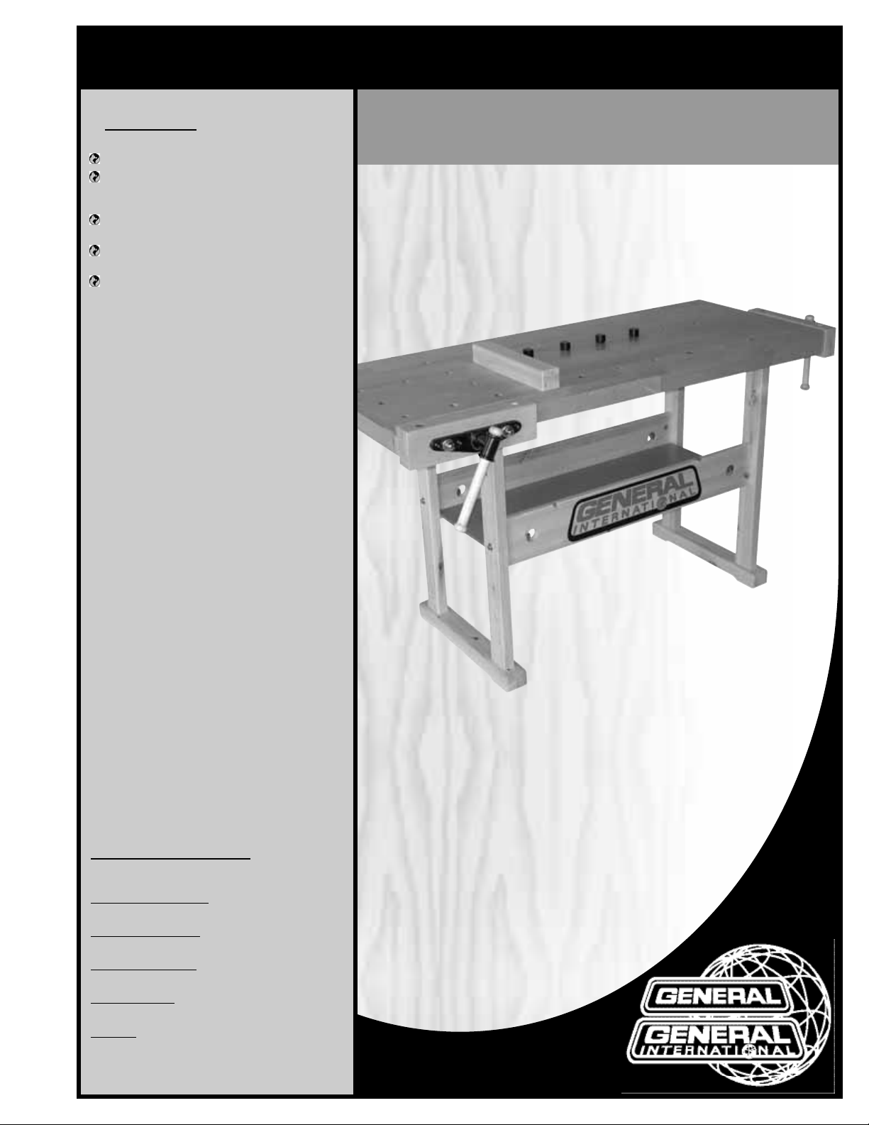
FEATURES
Solid 1”thick laminated birch table top.
Includes both front and end vises with a
double row of bench dog holes in the
table for each vise.
Sturdy hardwood support frame with large
storage shelf.
Includes four bench dogs and one wooden stopper bar.
Durable lacquer finish on all wooden components.
SPECIFICATIONS
TABLE DIMENSIONS
54”x 21” x 1” (1372 x 533 x 25.4 mm)
VISE DIMENSIONS
13”x 3 1/2” x 2” (330 x 90 x 50 mm)
MAX
VISE TRAVEL
4”(100 mm)
T
ABLE HEIGHT
31 3⁄4”(810 mm)
WEIGHT
84 LBS (38 kg)
SETUP & OPERATION MANUAL
MODEL
#95-054
REVISION 1 - NOVEMBER 10/09
© COPYRIGHT GENERAL INTERNATIONAL 11/2009
54” X 21” BIRCH WORKBENCH
Page 2

THANK YOU
for choosing this General®International model 95-054 54” x 21”
Birch Workbench. This workbench has been carefully tested and inspected before shipment
and if properly used and maintained, will provide you with years of reliable service. To ensure
optimum performance and trouble-free operation, and to get the most from your investment,
please take the time to read this manual before assembling, installing and operating the unit.
The manual’s purpose is to familiarize you with the safe operation,basic function,and features
of this workbench as well as the set-up,maintenance and identification of its par ts and components. This manual is not intended as a substitute for formal woodworking instr uction, nor to
offer the user instruction in the craft of woodworking. If you are not sure about the safety of
performing a certain operation or procedure, do not proceed until you can confirm, from
knowledgeable and qualified sources,that it is safe to do so.
Once you’ve read through these instructions, keep this manual handy for future reference.
Disclaimer:
The information and specifications in this
manual pertain to the unit as it was supplied from the
factory at the time of printing. Because we are committed to making constant improvements, General
®
International reserves the right to make changes to
components, parts or features of this unit as deemed
necessary,without prior notice and without obligation to
install any such changes on previously delivered units.
Reasonable care is taken at the factory to ensure that
the specifications and information in this manual corres-
ponds with that of the unit with which it was supplied.
However, special orders and “after factory” modifications may render some or all information in this manual
inapplicable to your machine. Fur ther, as several generations of this model of workbench and several versions
of this manual may be in circulation, if you own an earlier or later version of this unit, this manual may not
depict your tool exactly.If you have any doubts or questions contact your retailer or our support line with the
model number of your unit for clarification.
GENERAL® INTERNATIONAL
8360 Champ-d’Eau, Montreal (Quebec) Canada H1P 1Y3
Telephone (514) 326-1161 • Fax (514) 326-5555 • www.general.ca
Page 3

GENERAL®& GENERAL®INTERNATIONAL WARRANTY
All component parts of General®, General® International and Excalibur by General
International ® products are carefully inspected during all stages of production and each unit
is thoroughly inspected upon completion of assembly.
Limited Lifetime
Warranty
Because of our commitment to quality and customer satisfaction, General® and General®
International agree to repair or replace any part or component which upon examination,
proves to be defective in either workmanship or material to the original purchaser for the life
of the tool.
However, the Limited Lifetime Warranty does not cover any product used for professional or commercial production purposes nor for industrial or educational applications. Such
cases are covered b y our Standar d 2-year Limited W arranty only.The Limited Lifetime Warranty
is also subject to the “Conditions and Exceptions”as lis ted below.
Standard 2-Year Limited Warranty
All products not covered by our lifetime warranty including products used in commercial,
industrial and educational applications are warranted for a period of 2 years (24 months) from
the date of purchase. General® and General® International agree to repair or replace any
part or component which upon examination, proves to be defective in either workmanship or
material to the original purchaser during this 2-year warranty period, subject to the “conditions
and exceptions”as lis ted below.
T
o file a Claim
To file a claim under our Standard 2-year Limited Warranty or under our Limited Lifetime
Warranty, all defective parts, components or machinery must be retur ned freight or postage
prepaid to General® International, or to a nearby distributor, repair center or other location
designated by General® International. For further details call our service department at 1-888949-1161 or your local distributor for assistance when filing your claim.
Along with the return of the product being claimed for warranty,a copy of the original proof
of purchase and a “letter of claim”must be included (a warranty claim form can also be used
and can be obtained,upon request,from General® International or an authorized distributor)
clearly stating the model and serial number of the unit (if applicable) and including an explanation of the complaint or presumed defect in material or workmanship.
CONDITIONS AND EXCEPTIONS:
This coverage is extended to the original purchaser only. Prior warranty registration is not
required but documented proof of purchase i.e. a copy of original sales invoice or receipt
showing the date and location of the purchase as well as the purchase price paid, must be
provided at the time of claim.
Warranty does not include f ailures,breakage or defects deemed after inspection by General®
or General® International to have been directly or indirectly caused by or resulting from;
improper use, or lack of or improper maintenance, misuse or abuse, negligence, accidents ,
damage in handling or transport, or normal wear and tear of any generally considered consumable parts or components .
Repairs made without the written consent of General® Interna tionallwill void all warranty.
Page 4

Carefully unpack and remove the unit,its components and tools from its shipping container and check for missing
or damaged items as per the list of contents below.
NOTE: Please report any damaged or missing items to your GENERAL® INTERNATIONAL distributor immediately.
UNPACKING
ADDITIONAL REQUIREMENTS FOR SET UP
• 12 mm and 14 mm open end wrenches
• Phillips Screwdriver
• Straightedge
A
C
D
K
L
N
R
O
LIST OF CONTENTS
QTY
A - TABLE...........................................................................................1
B - STOPPER BAR..............................................................................1
C - BENCH DOG (STOPPER).............................................................4
D - SCREW ASSEMBLY W/VISE SUPPORT BRACKET.........................2
E - RIGHT STAND..............................................................................1
F - LEFT STAND .................................................................................1
G - FRONT PANEL..............................................................................1
H - REAR PANEL................................................................................1
I - SHELF...........................................................................................1
J - VISE FACE...................................................................................2
K - VISE HANDLE ..............................................................................2
L - 4 & 5 MM ALLEN KEYS ...............................................................1
M - GLUE TUBE...................................................................................1
N - WOOD SCREW.........................................................................20
O - HALF-MOON NUT & HEX NUT ....................................................4
P - LONG SOCKET SCREW W/LOCK & FLAT WASHER ...................4
Q - SHORT SOCKET SCREW W/LOCK & FLAT WASHER ..................6
R - DOWEL........................................................................................8
B
E
F
G
H
I
J
M
Q
P
4
Page 5

ASSEMBLY INSTRUCTIONS
Note: The parts reference numbers in brackets in the assembly instructions in this manual refer to the reference number of
the item as shown in the parts diagram on page 8.
1. Insert 2 dowels (14) in the inside face of the right
stand (19) and insert 1 long socket screw (1) with
lock washer (2) and f lat washer (3) from the outside
face, as shown. Repeat on the other side of the
stand.
STAND ASSEMBLY
2. Attach the rear panel (18) to the right stand as
shown and secure with a half-moon nut (10) and
hex nut (5). Tighten with the supplied 5 mm Allen
key ( 4) and a 14 mm wrench as shown.
3. Repeat step 2 with the front panel (with logo). 4. Slide the shelf (17) along the slots on the bottom of
the front and rear panels as shown.
5. Repeat step 1 with the left stand then attach the left
stand to the front and rear panels as shown and
secure with a half-moon nut (10) and hex nut (5).
Tighten with the supplied 5 mm Allen key (4) and a
14 mm wrench as shown.
5
Page 6

6
TABLE ASSEMBLY
1. Disassemble both screw assemblies w/vise support bracket by loosening bolts A with a 12 mm
wrench.Remove and set aside bolts A, flat washers
B and screw assemblies C.
2. From the underside of the table,align the holes on
the vise support bracket D with the holes on the
side edge of the table E and secure using 6 wood
screws (13)(supplied).
A
B
C
D
E
3. Repeat with the second vise support bracket on
the front edge of the table F.
4. Turn the stand assembly up side down and careful-
ly lower it into the underside of the table as shown,
with the logo on the same side as the holes in the
table G.
F
5. Line up the 3 pre-drilled holes in each end of the
stand with the holes in the mounting blocks
secured under the table. Secure the s tand to the
table at both ends with 3 short socket screws (6),
lock washers (7) and flat washers (8). Tighten with
the supplied 4 mm Allen key.
11 N
G
Page 7

VISE ASSEMBLY
2. From under the table,re-install the flat washers and
bolts previously removed in section “TABLE ASSEMBBLY”, step 1, and tighten with a 12 mm wrench.
H
I
VISE & BENCH DOG USAGE EXAMPLES
The supplied vises and bench dogs can be used in a wide variety of situations and configurations where clamping
or securing a workpiece to the bench may be useful. Here are but a few examples of the possible uses for the vises
and bench dogs.You may discover, or already have many others , based on your own specific shop needs.
7
1. Insert the screw assembly (11N) through the mid-
dle hole of a vise face (22N) then thread the screw
in the middle hole of the vise support bracket, on
the right side of the workbench.
Note:
Do not thread the screw all the way in yet.
4. Remove the end cap (21) from both ends of one
vise handle (20) then insert the handle through
handle holder as shown and glue the caps back
on the handle using the supplied glue tube.
5. Repeat steps 1 to 4 with the second screw assembly on the front edge of the workbench.
3. Place a straightedge H on the table and vise face.
Manually adjust the vise face I so it is leveled with
the table top then firlmy tighten the screw (11N) to
secure the vise face in position. With the vise face
leveled with the table top,secure the screw assembly to the vise face with 4 wood screws (13).
Page 8

18N
DIAGRAM
8
Page 9

9
PARTS LIST
95-054
REF N0. PART N0. DESCRIPTION SPECIFICATION QTY
1 95054-1 SOCKET SCREW M8X4-120MM 4
2 95054-2 LOCK WASHER ØX8-ØX13 4
3 95054-3 FLAT WASHER ØX8-ØX19 4
4 95054-4 ALLEN KEY 5MM 1
5 95054-5 HEX NUT M8X14 4
6 95054-6 SOCKET SCREW M6X55MM 6
7 95054-7 LOCK WASHER ØX6-ØX11 6
8 95054-8 FLAT WASHER ØX6-ØX19 6
9 95054-9 ALLEN KEY 4MM 1
10 95054-10 HALF-MOON NUT 30-15 4
11N 95054-11N SCREW M20X294MM 2
12N 95054-12N SUPPOR T ROD ØX19X155MM 4
13 95054-13 WOOD SCREW 4MMX25MM 20
14 95054-14 PIN ØX10X40MM 8
15 95054-15 GLUE TUBE 1
16 95054-16 TABLE 1
17 95054-17 SHELF 1
18 95054-18 REAR PANEL (WITHOUT LOGO) 1
18N 95054-18N FRONT PANEL (WITH LOGO) 1
19 95054-19 RIGHT STAND 1
20 95054-20 VISE HANDLE 2
21 95054-21 END CAP 2
22N 95054-22 VISE FACE 2
23 95054-23 LEFT STAND 1
24 95054-24 STOPPER BAR 1
25 95054-25 BENCH DOG (STOPPER) 4
28N 95054-28N VISE SUPPOR T BRACKET 2
31 95054-31 FLAT WASHER 4
32 95054-32 CAP NUT 4
33 95054-33 FLAT WASHER 4
34 95054-34 HEX HEAD BOLT 4
Page 10

IMPORTANT
When ordering replacement parts, always give the model number, serial number of the machine and
part number. Also a brief description of each item and quantity desired.
8360 Champ-d’Eau, Montreal (Quebec) Canada H1P 1Y3
Tel.: (514) 326-1161
Fax: (514) 326-5565 - Parts & Service / Fax: (514) 326-5555 - Order Desk
orderdesk@general.ca
www.general.ca
MODEL 95-054
 Loading...