

Page 1
SETUP & OPERATION MANUAL
FEATURES
One-piece heavy-duty thick steel upper frame
eliminates vibration.
Welded one-piece base made of high-quality
steel with built-in coolant tank and recovery tray.
Precision machined and balanced high-quality
cast-iron wheels.
Automatic shut-off at the end of cutting cycle.
Chip brush and blade guard included.
Fully adjustable blade guide bearings.
Built-in blade tension indicator.
Coolant system with built-in tank and pump.
Cast-iron vise with one fixed and one quick-
positioning moveable jaw.
Adjustable hydraulic down feed control.
4 blade speeds to accommodate a wide range
of cutting needs.
Magnetic safety switch with lock-out key.
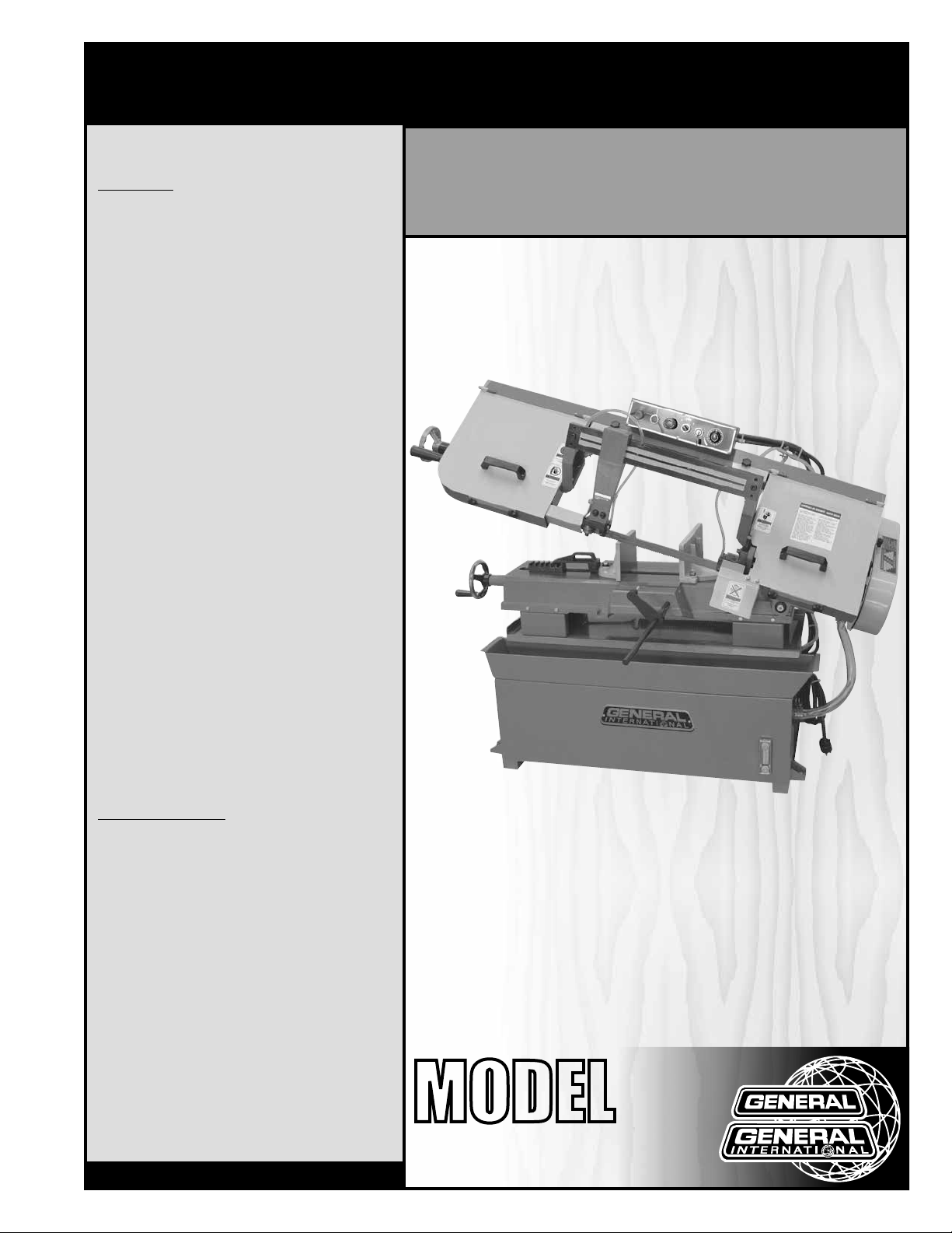
9” X 16” METAL CUTTING BANDSAW
SPECIFICATIONS
• Cutting capacity at 90º (Rectangular)
8 7/8” x 13 1/2” (225 x 345 mm)
& 1 3/8” x 15 3/4” (35 x 400 mm)
• Cutting capacity at 90º (Round)
8 7/8” (225 mm)
• Cutting capacity at 45º (Rectangular)
6 1/2” x 8 7/8” (165 x 225 mm)
• Cutting capacity at 45º (Round)
6 1/2” (165 mm)
• Blade size
1” X 0.032” X 119 1/2” (27 X 0.9 X 3035 mm)
• Blade speeds
82, 132, 170, 235 fpm (25, 40, 51, 71 mpm)
• Overall dimensions
64 3/4” x 44 1/4” x 42 1/2” (1645 x 1125 x 1080 mm)
• Motor
1/2 HP, 240 V, 1 PH, 8 A
• Shipping weight / Net weight
638 lbs (290 kg) / 543 lbs (247 kg)
Version #2_Revision #2 - April 2015
© Copyright General International
MODEL
#
90-790
Page 2

GENERAL® INTERNATIONAL
8360 Champ-d’Eau, Montreal (Quebec) Canada H1P 1Y3
Telephone (514) 326-1161 • Fax (514) 326-5555 • www.general.ca
THANK YOU
for choosing this General® International model 90-790 9” x 16”
Metal Cutting Bandsaw. This bandsaw has been carefully tested and inspected before shipment
and if properly used and maintained, will provide you with years of reliable service. For your
safety, as well as to ensure optimum performance and trouble-free operation, and to get the most
from your investment, please take the time to read this manual before assembling, installing and
operating the unit.
The manual’s purpose is to familiarize you with the safe operation, basic function, and
features of this bandsaw as well as the set-up, maintenance and identification of its parts and
components. This manual is not intended as a substitute for formal metalworking instruction,
nor to offer the user instruction in the craft of metalworking. If you are not sure about the safety
of performing a certain operation or procedure, do not proceed until you can confirm, from
knowledgeable and qualified sources, that it is safe to do so.
Once you’ve read through these instructions, keep this manual handy for future reference.
DISCLAIMER: The information and specifications
in this manual pertain to the unit as it was supplied
from the factory at the time of printing. Because we
are committed to making constant improvements,
General® International reserves the right to make
changes to components, parts or features of this unit
as deemed necessary, without prior notice and without
obligation to install any such changes on previously
delivered units. Reasonable care is taken at the factory
to ensure that the specifications and information in this
manual corresponds with that of the unit with which it
was supplied. However, special orders and “after factory”
modifications may render some or all information in
this manual inapplicable to your machine. Further,
as several generations of this model of Metal Cutting
Bandsaw and several versions of this manual may be
in circulation, if you own an earlier or later version of
this unit, this manual may not depict your unit exactly. If
you have any doubts or questions contact your retailer
or our support line with the model and serial number of
your unit for clarification.
Page 3

GENERAL® INTERNATIONAL WARRANTY
All component parts of General® International and Excalibur by General International® products
are carefully inspected during all stages of production and each unit is thoroughly inspected upon
completion of assembly.
Limited Lifetime Warranty
Because of our commitment to quality and customer satisfaction, General® International agrees to
repair or replace any part or component which upon examination, proves to be defective in either
workmanship or material to the original purchaser for the life of the tool. However, the Limited Lifetime
Warranty does not cover any product used for professional or commercial production purposes nor
for industrial or educational applications. Such cases are covered by our Standard 2-year Limited
Warranty only. The Limited Lifetime Warranty is also subject to the “Conditions and Exceptions” as listed
below.
Standard 2-Year Limited Warranty
All products not covered by our lifetime warranty including products used in commercial, industrial
and educational applications are warranted for a period of 2 years (24 months) from the date of
purchase. General® International agrees to repair or replace any part or component which upon
examination, proves to be defective in either workmanship or material to the original purchaser during
this 2-year warranty period, subject to the “conditions and exceptions” as listed below.
To file a Claim
To file a claim under our Standard 2-year Limited Warranty or under our Limited Lifetime Warranty,
all defective parts, components or machinery must be returned freight or postage prepaid to
General® International, or to a nearby distributor, repair center or other location designated by
General® International. For further details call our service department at 1-888-949-1161 or your local
distributor for assistance when filing your claim.
Along with the return of the product being claimed for warranty, a copy of the original proof of purchase
and a “letter of claim” must be included (a warranty claim form can also be used and can be obtained,
upon request, from General® International or an authorized distributor) clearly stating the model and
serial number of the unit (if applicable) and including an explanation of the complaint or presumed
defect in material or workmanship.
CONDITIONS AND EXCEPTIONS:
This coverage is extended to the original purchaser only. Prior warranty registration is not required but
documented proof of purchase i.e. a copy of original sales invoice or receipt showing the date and
location of the purchase as well as the purchase price paid, must be provided at the time of claim.
Warranty does not include failures, breakage or defects deemed after inspection by
General® International to have been directly or indirectly caused by or resulting from; improper use,
or lack of or improper maintenance, misuse or abuse, negligence, accidents, damage in handling or
transport, or normal wear and tear of any generally considered consumable parts or components.
Repairs made without the written consent of General® International will void all warranty.
Page 4

TABLE OF CONTENTS
Rules for safe operation .....................................................................................................5
Electrical requirements ...................................................................................................... 6
Identification of main parts and components .................................................................. 7
Unpacking .......................................................................................................................... 8
Basic functions ...................................................................................................................8
Placement within the shop/Safety zone ............................................................................9
Assembly instructions ................................................................................................... 9-12
Installing the control box ................................................................................................................................... 9
Installing the motor ...................................................................................................................................... 10-11
Installing the pulley cover ................................................................................................................................11
Installing the workpiece stop .......................................................................................................................... 12
Basic adjustments and controls ................................................................................. 12-21
Connecting to a power source .......................................................................................................................12
Main On/Off magnetic switch ........................................................................................................................12
Overload protection .........................................................................................................................................13
Changing the blade ................................................................................................................................... 13-14
Adjusting blade tension ................................................................................................................................... 15
Adjusting blade tracking ................................................................................................................................. 15
Squaring the blade to the table work ............................................................................................................ 16
Squaring the vise to the blade ........................................................................................................................ 16
Adjusting the quick-set vise ............................................................................................................................. 17
Adjusting the right and left blade guides ...................................................................................................... 17
Adjusting the carbon block guides ................................................................................................................ 18
Adjusting the right and left thrust bearings ................................................................................................... 18
Adjusting the blade guard .............................................................................................................................. 19
Changing speeds ............................................................................................................................................. 19
Speed selection chart ...................................................................................................................................... 19
Cutting feed rate/Saw arm tension ................................................................................................................ 20
Using the coolant pump .................................................................................................................................. 20
Filling the coolant tank ..................................................................................................................................... 20
Securing and leveling the machine...............................................................................................................21
Operating Instructions ..................................................................................................... 21
Checklist before starting .................................................................................................................................. 21
Operations step-by-step ................................................................................................................................... 21
Maintenance .................................................................................................................... 22
Cleaning ............................................................................................................................................................ 22
Lubrication ......................................................................................................................................................... 22
Trouble shooting ......................................................................................................... 23-24
Parts list & diagrams ................................................................................................... 25-31
Contact information ........................................................................................................ 32
Page 5

RULES FOR SAFE OPERATION
To help ensure safe operation, please take a moment to learn the machine’s applications and limitations,
as well as potential hazards. General
harmless for any injury that may result from the improper use of it’s equipment.
1. Do not operate the bandsaw when tired, distracted
or under the effects of drugs, alcohol or any medI cation that impairs reflexes or alertness.
2. The work area should be well lit, clean and free
of debris.
3. Keep children and visitors at a safe distance when
the bandsaw is in operation; do not permit them to
operate the bandsaw.
4. Childproof and tamper proof your shop and all ma chinery with locks, master electrical switches and
switch keys, to prevent unauthorized or unsupervised
use.
5. STAY ALERT! Give your work your undivided attention.
Even a momentary distraction can lead to serious
injury.
6. Fine particulate dust is a carcinogen that can be
hazardous to health. Work in a well-ventilated area.
Wear face, eye, ear, respiratory and body protec tion devices.
7. Do not wear loose clothing, gloves, bracelets,
necklaces or other jewelry while the bandsaw is in
operation.
8. Be sure that adjusting wrenches, tools, drinks and
other clutter are removed from the machine and/or
the table surface before operating.
9. Keep hands well away from the blade and all
moving parts. Use a brush, not hands, to clear away
chips and dust.
10. Adjust and position the blade guards as close as
possible to the workpiece.
11. Adjust blade tension and tracking before starting to
cut.
12. Blade teeth must point down toward the table.
13. Be sure that the blade has gained full operating
speed before starting to cut.
14. Always use a clean, properly sharpened blade.
Dirty or dull blades are unsafe and can lead to
accidents.
®
International disclaims any real or implied warranty and holds itself
15. Use suitable workpiece support if the workpiece
does not have a flat surface.
16. Make sure the workpiece is securely held in place
in the vise.
17. Do not work on long stock without adequate sup port on the out feed end of the table.
18. Do not push or force stock into the blade. The band saw will perform better and more safely when work ing at the rate for which it was designed.
19. Avoid working from awkward or off balance posi tions. Do not overreach and keep both feet on floor.
20. Keep guards in place and in working order. If a
guard must be removed for maintenance or clean ing be sure it is properly re-attached before using
the saw again.
21. Never leave the machine unattended while it is run- ning or with the power on.
22. Use of parts and accessories NOT recommended
by General
malfunction or risk of injury.
23. Never stand on machinery. Serious injury could re sult if the tool is tipped over or if the cutting tool is
unintentionally contacted.
24. Always disconnect the saw from the power
source before servicing or changing accessories
such as blades, or before performing any mainte nance or cleaning, or if the machine will be left
unattended.
25. Make sure that the switch is in the “OFF” position
before plugging in the power cord.
26. Make sure the machine is properly grounded. If
equipped with a 3-prong plug it should be used with
a three-pole receptacle. Never remove the third
prong.
27. Do not use this bandsaw for other than its intended use.
If used for other purposes, General® International
disclaims any real or implied warranty andholds itself
harmless for any injury, which may resultfrom that use.
®
International may result in equipment
5
Page 6
ELECTRICAL REQUIREMENTS
BEFORE CONNECTING THE MACHINE TO THE POWER SOURCE, VERIFY THAT THE VOLTAGE OF YOUR POWER SUPPLY CORRESPONDS WITH THE VOLTAGE SPECIFIED ON THE MOTOR I.D. NAMEPLATE. A POWER SOURCE WITH
GREATER VOLTAGE THAN NEEDED CAN RESULT IN SERIOUS INJURY TO THE USER AS WELL AS DAMAGE TO THE
MACHINE. IF IN DOUBT, CONTACT A QUALIFIED ELECTRICIAN BEFORE CONNECTING TO THE POWER SOURCE.
THIS TOOL IS FOR INDOOR USE ONLY. DO NOT EXPOSE TO RAIN OR USE IN WET OR DAMP LOCATIONS.
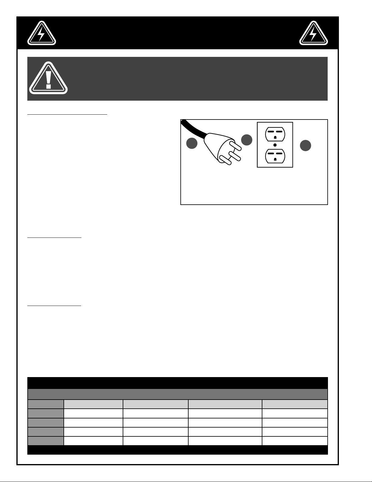
GROUNDING INSTRUCTIONS
In the event of an electrical malfunction or short circuit, grounding reduces the risk of electric shock to
the operator.
The motor of this machine is wired for 240 V single
phase operation and is equipped with a 3-conductor cord A and a 3-prong grounded plug B to fit a
matching grounding type receptacle C.
DO NOT MODIFY THE PLUG PROVIDED! If it will not
fit your receptacle, have the proper receptacle installed by a qualified electrician.
CHECK with a qualified electrician or service person
if you do not completely understand these grounding instructions, or if you are not sure the tool is properly grounded.
A
B
C
CIRCUIT CAPACITY
Make sure that the wires in your circuit are capable of handling the amperage draw from your machine, as
well as any other machines that could be operating on the same circuit.
If you are unsure, consult a qualified electrician. If the circuit breaker trips or the fuse blows regularly, your
machine may be operating on a circuit that is close to its amperage draw capacity.
However, if an unusual amperage draw does not exist and a power failure still occurs, contact a qualified
technician or our service department.
EXTENSION CORDS
The use of an extension cord is not generally recommended for 240 V equipment. If you find it necessary,
use only 3-wire extension cords that have 3-prong grounding plug and a matching 3-pole receptacle that
accepts the tool’s plug. Repair or replace a damaged extension cord or plug immediately.
If you find it necessary to use an extension cord with your machine make sure the cord rating is suitable for
the amperage listed on the motor I.D. plate. An undersized cord will cause a drop in line voltage resulting in
loss of power and overheating.
The accompanying chart shows the correct size extension cord to be used based on cord length and motor
I.D. plate amp rating. If in doubt, use the next heavier gauge. The smaller the number, the heavier the gauge.
TABLE - MINIMUM GAUGE FOR CORD
EXTENSION CORD LENGTH
AMPERES 50 feet 100 feet 200 feet 300 feet
< 5
6 to 10
10 to 12
12 to 16
*NR = Not Recommended
18 16 16 14
18 16 14 12
16 16 14 12
14 12 *NR *NR
6
Page 7
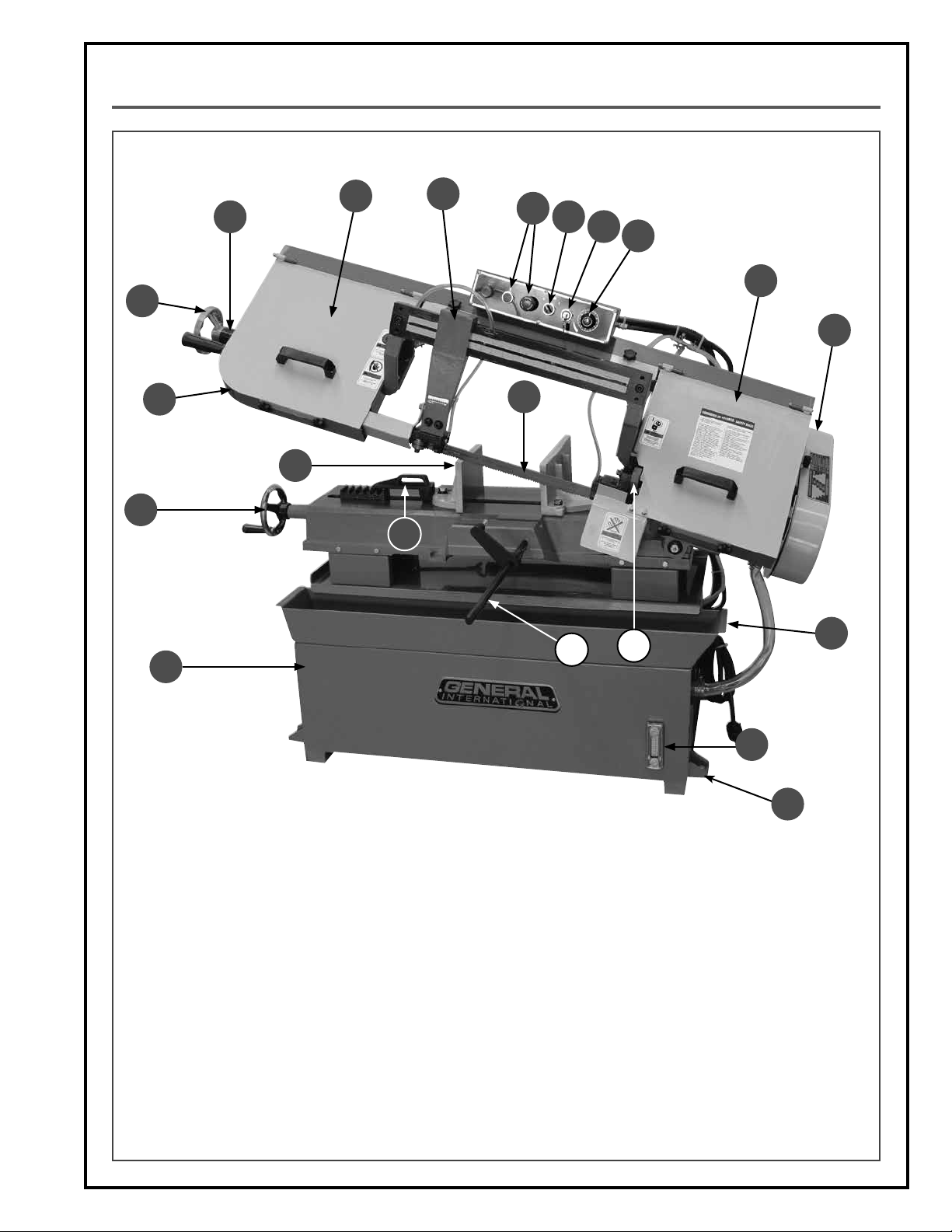
IDENTIFICATION OF MAIN PARTS AND COMPONENTS
D
A
I
R
P
E
F
G
H
I
K
B
J
C
S
L
O
Q
N
A. BLADE TENSIONING HANDLE
B. BLADE ARM
C. VISE
D. VISE ADJUSTMENT HANDWHEEL
E. ON/OFF SWITCH
F. COOLANT PUMP SWITCH
G. MAIN OFF SWITCH WITH SAFETY KEY
H. HYDRAULIC DOWNFEED CONTROL VALVE
I. WHEEL COVERS (2)
J. BLADE
M
T
K. PULLEY COVER
L. COOLANT RECOVERY TRAY
M. COOLANT LEVEL GAUGE
N. STAND
O. WORKPIECE STOP
P. BLADE GUARD & LEFT BLADE GUIDE
Q. RIGHT GUIDE BEARINGS
R. BLADE TENSION INDICATOR
S. VISE QUICK ADJUSTMENT HANDLE
T. LEVELING FEET (4)
7
Page 8
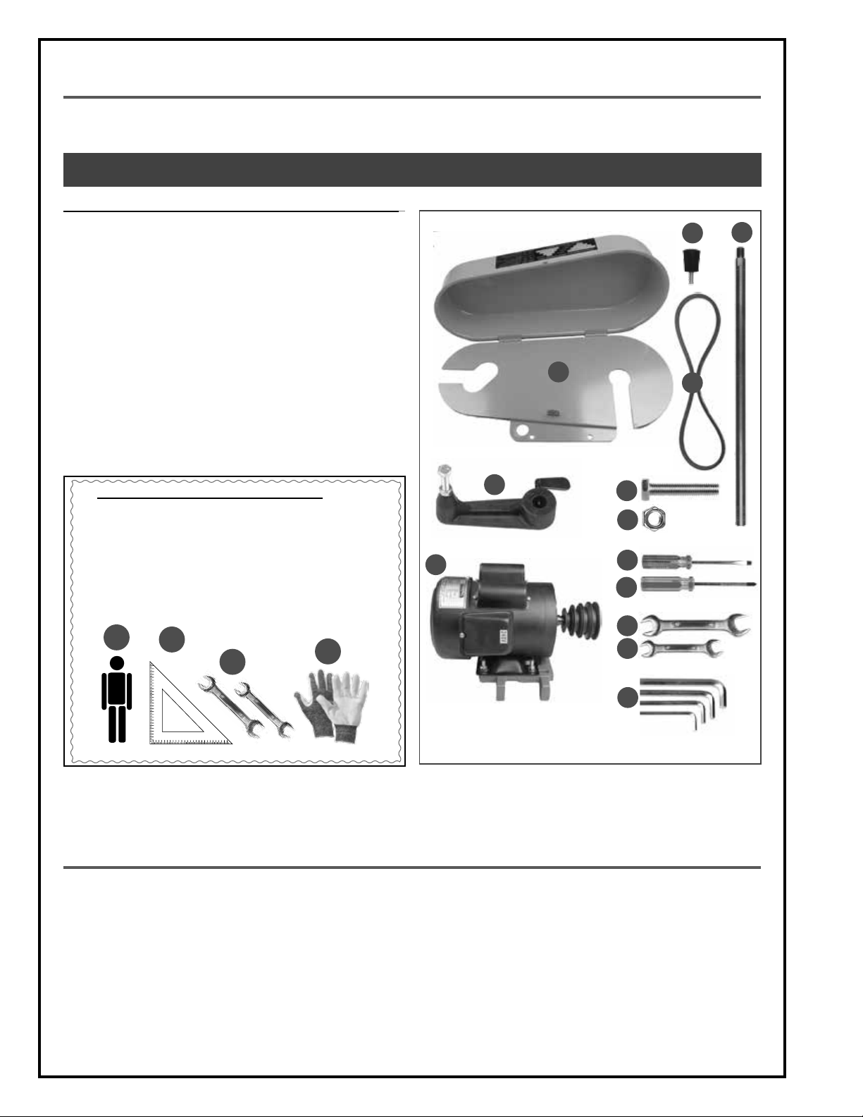
UNPACKING
Carefully unpack and remove the unit and its components from its shipping container and check for missing or
damaged items as per the list of contents below.
NOTE: PLEASE REPORT ANY DAMAGED OR MISSING ITEMS TO YOUR GENERAL® INTERNATIONAL DISTRIBUTOR IMMEDIATELY.
LIST OF CONTENTS QTY
A. PULLEY COVER ......................................................................... 1
B. LOCK KNOB ............................................................................. 1
C. STOP SHAFT .............................................................................. 1
D. BELT...........................................................................................1
E. WORKPIECE STOP .................................................................... 1
F. HEX HEAD BOLT ....................................................................... 4
G. NUT ........................................................................................... 4
H. FLAT HEAD SCREWDRIVER .......................................................1
I. PHILLIPS SCREWDRIVER .......................................................... 1
J. 17 -19 MM WRENCH................................................................ 1
K. 11 -13 MM WRENCH................................................................ 1
L. 3, 4, 5 6 MM ALLEN KEYS ......................................................... 1
M. MOTOR .................................................................................... 1
B
A
D
C
ADDITIONAL REQUIREMENTS FOR SET UP
A. EXTRA PERSON FOR HELP WITH LIFTING
B. SQUARE
C. 10 & 14 MM WRENCHES
D. GLOVES
A
B
E
M
D
F
G
H
I
J
K
C
L
BASIC FUNCTIONS
This 9” x 16” horizontal metal cutting band saw is designed for horizontal cutting in metalworking and machine
shops for cutting various types of bar stock, channel stock, piping, and thin-walled tubing.
With four blade speeds to accommodate a wide range of cutting needs, the unit features an automatic hydraulically controlled down feed with auto shut off at the end of the cutting cycle.
The coolant system with built-in pump is designed to supply a continuous flow of liquid coolant to the cutting area
to prevent overheating of both the blade and the workpiece, providing cleaner cuts and prolonging blade life.
8
Page 9
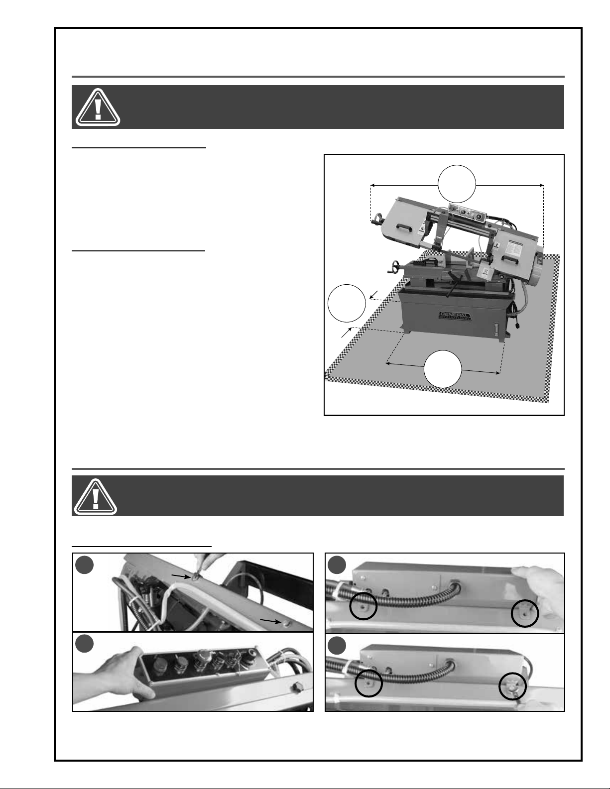
PLACEMENT WITHIN THE SHOP / SAFETY ZONE
THIS METAL CUTTING BANDSAW 90-790 IS HEAVY. DO NOT OVER-EXERT. A HOIST OR FORKLIFT WITH STRAPS SHOULD
BE USED TO LIFT THIS MACHINE. TO LIMIT THE RISK OF SERIOUS INJURY OR DAMAGE TO THE MACHINE, ANY EQUIPMENT USED TO LIFT THIS MACHINE SHOULD HAVE A RATED CAPACITY IN EXCESS OF 543 LBS (247 KG).
PLACEMENT WITHIN THE SHOP
This machine should be installed and operated only on
a solid, flat and stable floor that is able to support the
weight of the machine (543 lbs - 247 kg) and the operator. Using the dimensions shown as a guideline, plan for
placement within your shop that will allow the operator
to work unencumbered and unobstructed by foot traffic (either passing shop visitors or other shop workers) or
other tools or machinery.
ESTABLISHING A SAFETY ZONE
For shops with frequent visitors or multiple operators,
it is advisable to establish a safety zone around shop
machinery. A clearly defined “no-go” zone on the floor
around each machine can help avoid accidents that
could cause injury to either the operator or the shop
visitor.
It is advisable to take a few moments to either paint
(using non-slip paint) or using tape, define on the floor
the limits or perimeter of each machines safety zone.
Take steps to ensure that all operators and shop visitors are aware that these areas are off limits whenever
a machine is running for everyone but the individual
operating the unit.
19"
64"
40"
ASSEMBLY INSTRUCTIONS
BEFORE ASSEMBLING, MAKE SURE THAT THE SWITCH IS IN THE “OFF” POSITION AND THAT THE POWER CORD IS
UNPLUGGED. DO NOT PLUG IN OR TURN ON THE MACHINE UNTIL YOU HAVE COMPLETED THE ASSEMBLY AND
INSTALLATION STEPS DESCRIBED IN THIS SECTION OF THE MANUAL.
INSTALLING THE CONTROL BOX
A
B
1. Remove the bolts and washers located on the top
of the saw arm A using a 10 mm wrench and then
position the control box on the arm B.
C
D
2. Align the box mounting holes with the correspond-
ing holes in the machine C and secure the box using the bolts and washers you just removed D.
9
Page 10
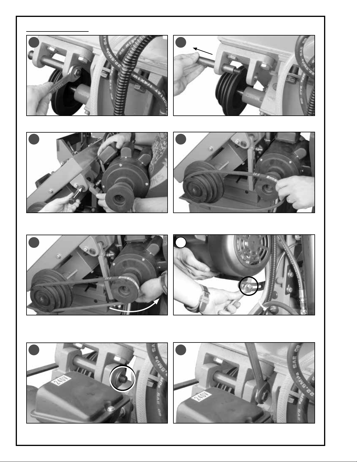
INSTALLING THE MOTOR
A
1. Remove the nut and the flat washer from the motor
mounting shaft with a 19 mm wrench A.
C
B
2. Remove the shaft B.
D
3. With assistance, position the motor base onto its
mounting bracket and then re-insert the mounting
shaft all the way in C.
E
5. Pull back the motor as much as possible to tension
the belt and hold it in place E.
G
4. Install the belt on the pulleys D.
F
6. Secure the motor base to its mounting bracket us-
ing the bolt and the washer already installed F.
Note: Push on the belt with your finger. The belt should not
move more than 1/2”
H
7. Re-install the flat washer on the motor mounting
shaft G.
10
8. Gently retighten the nut H to avoid breaking the re-
tention ring on the shaft.
Page 11

BEFORE ASSEMBLING, MAKE SURE THAT THE SWITCH IS IN THE “OFF” POSITION AND THAT THE POWER CORD IS
UNPLUGGED. DO NOT PLUG IN OR TURN ON THE MACHINE UNTIL YOU HAVE COMPLETED THE ASSEMBLY AND
INSTALLATION STEPS DESCRIBED IN THIS SECTION OF THE MANUAL.
INSTALLING THE MOTOR (CONTINUED)
A B
9. Place a straightedge A to verify that the two pulleys
are aligned. If they are not aligned, go to the next
step.
INSTALLATING THE PULLEY COVER
C
1. Remove the bolts and flat washers C installed on
the machine with a 13 mm wrench.
E F
10. Loosen the four nuts located in the motor base B
with a 14 mm wrench. Slide the motor on its base to
align the pulleys. Tighten the four nuts B.
D
2. Slide the right side pulley cover behind the motor
pulley D.
3. Then slide the cover behind the other pulley E. 4. Align the mounting holes F with the corresponding
holes in the machine.
G
5. Attach the cover to the machine using the bolts and
flat washers G removed in step 1.
H
6. Screw the lock knob in place H to keep the cover
door closed during operation.
11
Page 12

BEFORE ASSEMBLING, MAKE SURE THAT THE SWITCH IS IN THE “OFF” POSITION AND THAT THE POWER CORD IS
UNPLUGGED. DO NOT PLUG IN OR TURN ON THE MACHINE UNTIL YOU HAVE COMPLETED THE ASSEMBLY AND
INSTALLATION STEPS DESCRIBED IN THIS SECTION OF THE MANUAL.
INSTALLING THE WORKPIECE STOP
A B
1. Screw the stop bar into its mounting hole and se-
cure it using a 17 mm wrench A.
2. Slide the workpiece stop onto the bar as shown
and tighten the thumbscrew to secure it in place B.
BASIC ADJUSTMENTS & CONTROLS
TO REDUCE THE RISK OF SHOCK OR FIRE DO NOT OPERATE THE UNIT WITH A DAMAGED POWER CORD OR PLUG. REPLACE DAMAGED CORD OR PLUG IMMEDIATELY. TO AVOID UNEXPECTED OR UNINTENTIONAL START-UP, MAKE SURE
THE POWER SWITCH IS IN THE OFF POSITION BEFORE CONNECTING TO A POWER SOURCE.
CONNECTING TO A POWER SOURCE
Once the assembly steps have been completed, plug
the power cord into an appropriate outlet.
Refer back to the section entitled “Electrical Require
ments” and make sure all requirements and grounding
instructions are followed.
When operations have been completed unplug the
saw from the power source.
MAIN ON/OFF MAGNETIC SWITCH
This machine is equipped with a magnetic safety switch
designed to protect the unit and the user from power
surges, power outages and unwanted or unintentional
start-up.
The switch assembly is equipped with a safety lock-out
switch with removable key E, a green “start” button F, a
red “stop” button with twist lock-out feature D. Once the
button D has been pressed, the machine can only be
started by turning the inner part of the button D to the
right to release the stop button.
The limit switch H is designed to make contact with the
stop bolt I and turn off the machine when the cut is completed. If necessary the stop bolt I can be adjusted by
loosening the jam nut J and adjusting the bolt height I
and then retightening the jam nut to secure the bolt in place J.
The switch G allows you to turn the coolant system pump on or off. To start the pump, turn the switch to the right. To
stop the pump, turn the switch to the left.
The power light indicator C indicates that the machine is connected to the power source.
-
C
D
F
E
G
SWITCH OFF
TO AVOID UNEXPECTED OR UNINTENTIONAL
START-UP, MAKE SURE THAT THE POWER SWITCH
IS IN THE OFF POSITION BEFORE CONNECTING
TO A POWER SOURCE.
H
I
J
12
Page 13

MAKE SURE THE MACHINE HAS BEEN TURNED OFF AND UNPLUGGED FROM THE POWER SOURCE BEFORE PERFORMING ANY MAINTENANCE OR ADJUSTMENTS.
OVERLOAD PROTECTION
The magnetic safety switch on this machine is equipped with an overload protection feature. To prevent an electrical overload from damaging the motor, in the event of a spike in line voltage or amperage draw, the internal
overload protector will automatically be tripped, thereby cutting off power to the motor.
Common causes of such overloads:
1. Overworking the motor by cutting at a feed speed that is too agressive, thereby causing an increase in power
consumption and a spike in amperage draw.
2. An electrical extension cord that is too long or not the correct gauge of wire, which can also cause an increase in amperage draw. If an electric extension cord must be used, follow the instructions and refer to the
chart in the electrical requirements section at the beginning of this manual.
3. Overworked circuit caused by operating on a circuit that is close to its amperage draw capacity. Make sure
the circuit being used is capable of handling the amperage draw from this machine as well as any other
electrical devices operating on the same circuit. If you are unsure, consult a qualified electrician.
To reset the overload protection switch after it has been tripped proceed as follows:
B
A
C
Loosen the cap screw A with a 5 mm Allen key and open the access door. Press the button B to reset the overload
protection switch. Close the access door and retighten the cap screw A before restarting the machine.
Note: If the machine still does not work after resetting the overload protector, check the fuses C and replace them if necessary with identical ones (replacement fuses are provided).
CHANGING THE BLADE
There are a variety of different types of bandsaw blades on the market to suit various cutting applications. Your
results may vary based on usage, experience and personal preference. Ask your local tool dealer for suggestions
for bandsaw blades in 0.032” (0,9 mm) thickness and 1” (27 mm) widths, based on what is available in your area.
Ideal blade length for model 90-790 is 119” (3035 mm).
Note: Generally speaking, because one wheel height is somewhat adjustable (to allow for blade tensioning), a blade
length variation of plus or minus 1/2” from the “ideal blade length” can be accommodated.
E
D
1. To lock the blade arm in the up position shut off the
hydraulic valve D by turning it all the way clockwise.
2. Raise the arm a little as shown E.
13
Page 14

BLADE
CHANGING THE BLADE (CONTINUED)
A B
1. Loosen the two lock knobs A and then open the
front blade cover.
C
3. Remove the two lock knobs C and remove the cen-
ter blade cover C.
E F
2. Loosen the two lock knobs B and then open the
rear blade cover.
D
4. Loosen the blade guard lever and position the blade
guard all the way to your right. Retighten the lever.
5. Unscrew the bolt E with a 13 mm wrench and re-
move the blade guard.
G
5. Loosen the blade by turning the tension handle
counterclockwise and then remove the blade using gloves to reduce the risk of injury G.
14
6. Remove the metal brush with a 10 mm wrench F.
H I
WHEEL SHOULDER
SHOULDER
5. Install the blade. To tension the blade, hold the blade
against the shoulder of the wheels H & I, then turn the
tension handle.
Note: See section “Adjusting blade tension”.
BLADE
BLADE
WHEEL SHOULDER
BLADE
Page 15

MAKE SURE THE MACHINE HAS BEEN TURNED OFF AND UNPLUGGED FROM THE POWER SOURCE BEFORE PERFORMING ANY MAINTENANCE OR ADJUSTMENTS.
ADJUSTING BLADE TENSION
A properly tensioned blade is critical to obtaining maximum performance from any bandsaw. A properly tensioned blade will last longer and be much less likely to break prematurely.
If the blade tension is too loose you will notice that the blade will have a tendency to drift or slip off-line when
cutting and you will have more difficulty controlling your cuts. A blade that is tensioned too tightly will break prematurely.
The following information can be used as a guideline or starting point to assist you in determining ideal blade
tension. This bandsaw is equipped with a blade tension
scale, which can be used as a reference for the ideal
setting with various blade widths.
To adjust the blade tension:
1. Lower the arm into the horizontal position.
2. Turn the handwheel A clockwise to tension the
blade or counterclockwise to loosen. The blade
tension shoud be about 20,000 psi (1400 kg/cm²).
Use the tension indicator B with its graduated scale
A
in kg/cm².
3. Make a test cut on a sample piece and if needed,
re-adjust the blade tension.
B
ADJUSTING BLADE TRACKING
The front wheel of the machine is aligned at the factory, but it may be necessary to adjust the alignment after a
long period of use or after an important maintenance operation. This potential misalignment can be corrected by
adjusting the tilt of the front wheel.
C
1. Shut off the hydraulic downfeed control valve by
turning it all the way clockwise then lift the arm into
the highest position C.
F
E
D
2. Open the blade covers D.
G
SHOULDER
BLADE
BLADE
3. Loosen the 3 bolts F located on the back of the arm
with a 17 mm wrench.
4. Adjust blade tilt by loosening or tightening the 3
bolts E so that the blade touches the wheel shoulder G. Once blade tracking is adjusted, retighten
the 3 bolts F, and then close the wheel covers.
15
Page 16

MAKE SURE THE MACHINE HAS BEEN TURNED OFF AND UNPLUGGED FROM THE POWER SOURCE BEFORE PERFORMING ANY MAINTENANCE OR ADJUSTMENTS.
SQUARING THE BLADE TO THE WORK TABLE
A
1. Lower the saw arm into the horizontal position and
then place a square against the vise face and
against the blade A.
C
B
BLADE
SQUARE
WORK TABLE
SQUARE
WORK TABLE
Note: the saw blade must be perfectly squared to the table
B. If the blade is not square, go to the next step.
E
BLADE
BLADE
D
SQUARE
WORK TABLE
BLADE
SQUARE
WORK TABLE
2. Loosen the two screws C with a 6 mm Allen key. 3. Tighten or loosen the 3 set screws I with a 4 mm Al-
len key so that the blade is squared to the table E,
then retighten the two screws C.
SQUARING THE VISE TO THE BLADE
The quick-set vise can accommodate workpieces up to 13 1/2“ wide. It is also possible to adjust it to change the
cutting angle. Square it to the blade as follows:
H
F
A
VISE JAW
B
VISE JAW
SQ
U
A
BL
L
RE
AD
A
DE
E
I
SQ
U
A
B
L
RE
A
D
E
1. Lower the arm into the horizontal position and place
a square against one of the jaws and the blade.
G
J
2. To square the vise to the blade, loosen bolts F and
G. Manually adjust the jaw so that it is square to the
blade H and then retighten bolts F & G. Repeat all
the steps with the other jaw if necessary using the
bolts I & J.
16
Page 17

MAKE SURE THE MACHINE HAS BEEN TURNED OFF AND UNPLUGGED FROM THE POWER SOURCE BEFORE PERFORM-
0,001"
0,001"
ING ANY MAINTENANCE OR ADJUSTMENTS.
ADJUSTING THE QUICK-SET VISE
D
A
C
B
E
C
1. To use the quick adjustment vise, lift the handle A
and slide the jaw against the workpiece B while
holding the handle up.
ADJUSTING THE RIGHT AND LEFT BLADE GUIDES
The guide bearings keep the blade from moving from side to side during cutting and must be close to the blade
(but not touching) in order to ensure accurate cuts I.
Note: Before adjusting the blade guides, make sure the blade is tensioned and tracking properly. Re-adjust the blade
guides after each blade tension or tracking adjustment.
F
LEFT BLADE GUIDE
RIGHT BLADE GUIDE
2. Release the handle C and then secure the work-
piece in place by tightening the vise handwheel
D. Use the graduated scale E located behind the
machine as reference to position the vise.
G
H
1. Shut off the hydraulic valve by turning it clockwise,
then lift the arm to its highest position F.
2. To adjust the right blade guide, loosen the screw G
with a 6 mm Allen key G. 3. Turn the eccentric nut
H with a 19 mm wrench until the blade and bearing
are about 0.001” apart as shown I.
4. To lock the bearing in position, retighten nut H while
holding screw G. Repeat steps 2 to 4 for the other
bearing
5. Repeat steps 2 to 4 for the left blade guide assembly.
6. Make a test cut and re-adjust the blade guides if
needed.
I
17
Page 18

MAKE SURE THE MACHINE HAS BEEN TURNED OFF AND UNPLUGGED FROM THE POWER SOURCE BEFORE PERFORMING ANY MAINTENANCE OR ADJUSTMENTS.
ADJUSTING THE CARBON BLOCK GUIDES
A
LEFT CARBON GUIDE BLOCKS
1. Shut off the hydraulic valve then lift the arm to its
highest position A.
RIGHT CARBON GUIDE BLOCKS
B
C
2. To adjust the right carbon guide blocks, loosen one
of the blocks with a 5 mm Allen key B and position it along its slotted mounting hole so the block
is close to the blade without touching it C. Repeat
with other block and then with the left guide block
assembly.
ADJUSTING THE RIGHT AND LEFT THRUST BEARINGS
The thrust bearing keeps the blade from moving back and out of position when the workpiece is being fed into
the blade and must be very close to the back of the blade F to prevent damage to the blade when cutting. To
adjust it proceed as follows.
D
LEFT THRUST BEARING
RIGHT THRUST BEARING
E
1. Shut off the hydraulic valve then lift the arm to its
highest position D.
RIGHT THRUST BEARING
F
1/32”
3. Position the rear bearing bracket so that the thrust
bearing is close to, but not touching the back of the
blade F.
Note: The blade guide G must remain at least 1/32” behind
the blade teeth to prevent damage to the blade.
18
G
2. To adjust the left thrust bearing, loosen the rear
bearing bracket screws with a 6 mm Allen key E.
LEFT THRUST BEARING
I
J
3. For the front thrust bearing, loosen without remov-
ing screws I with a 6 mm Allen key. Slide the bearing along its slotted mounting holes so that the
thrust bearing is close to the back of the blade but
not touching K.
Note: The bearings J must remain at least 1/32” behind the
blade teeth to prevent damage to the blade.
K
Page 19

MAKE SURE THE MACHINE HAS BEEN TURNED OFF AND UNPLUGGED FROM THE POWER SOURCE BEFORE PERFORM-
AA
B
C
D
AA
B
C
D
POULIE DE L’ARBRE
POULIE DU MOTEUR
SPINDLE PULLEY
MOTOR PULLEY
ING ANY MAINTENANCE OR ADJUSTMENTS.
ADJUSTING THE BLADE GUARD
The blade guard should be adjusted based on the dimensions of the workpiece. To prevent the blade (which is flexible and which would not otherwise be supported) from slipping out of position when cutting, and to reduce the risk
of injury, a minimum amount of blade should be exposed. For a straight cut and to reduce the risk of twisting, loosen
lock lever A and position the blade guard as close as possible to the workpiece, then retighten the lock lever.
Note: the graduated scale B can be used as a reference when positionning the guard.
A
B
CHANGING SPEEDS
Note: The help from an assistant is recommended.
1. Loosen without removing the bolt C located under
the motor with a 14 mm wrench in order to loosen
the belt.
2. Open the pulley cover and position the belt on the
pulleys based on the desired blade speed (refer to
the chart below).
3. Pull the motor back towards you while tightening
the lock bolt C and then close and lock the pulley
cover.
SPEED SELECTION CHART
BLADE SPEED
BELT SPEED (fpm)
A
B
C
D
82
132
170
235
C
19
Page 20

MAKE SURE THE MACHINE HAS BEEN TURNED OFF AND UNPLUGGED FROM THE POWER SOURCE BEFORE PERFORMING ANY MAINTENANCE OR ADJUSTMENTS.
CUTTING FEED RATE/ SAW ARM TENSION
C
A
B
- Turn the knob A clockwise to increase the cutting
feed rate.
- Turn the knob A counterclockwise to decrease the
cutting feed rate.
Note: Forcing the blade into the workpiece increases the
risk of blade breakage and can affect the quality of the cut
(burrs, chips, etc.).
USING THE COOLANT PUMP
D
OFF
The switch D allows you to turn the pump on or off.
FILLING THE COOLANT TANK
ON
A tension spring helps lift the arm into the the vertical
position and slows down its descent. If too little tension
makes it difficult to raise the arm, proceed as follow:
1. Loosen the jam nut B and tighten bolt C a few turns.
2. Repeat as needed until desired tension is achieved
and then retighten the jam nut B.
Note: For less tension, loosen bolt C.
E
CLOSED
CLOSED
You can stop the flow of liquid coolant by closing the
two valves E.
G
F
Lift the recovery tray F to access and fill the coolant tank
with up to17 liters max of coolant.
Note: To prolong pump life and prevent blockages in the
coolant system, clean the filter G regularly using a compressed air blow gun to remove metal chips and other debris.
20
H
J
I
Note: Gauge H indicates coolant level. Remove the plug I
to drain the tank when necessary. Do not block the coolant
overflow vent J.
Page 21

MAKE SURE THE MACHINE HAS BEEN TURNED OFF AND UNPLUGGED FROM THE POWER SOURCE BEFORE PERFORMING ANY MAINTENANCE OR ADJUSTMENTS.
SECURING AND LEVELING THE MACHINE
Machine vibration during operation may cause the
machine to move, particularly when installed on uneven surfaces.
The bolt-down tabs and anchor bolts A can be used
to help keep the machine immobilized by either lowering the bolts against the floor to act as another point of
contact with the floor, or for permanent installations, by
drilling into the floor and bolting the machine in place.
A
OPERATING INSTRUCTIONS
CHECKLIST BEFORE STARTING
VERIFY ALL CHECK POINTS BEFORE STARTING. FAILURE TO COMPLY CAN RESULT IN SERIOUS INJURIES.
1. Make sure you and any assistants are wearing safe and appropriate workshop attire.
2. To reduce the risk of damage to the machine, as well as potential for personal injury, after initial set-up as well
as before each use, make sure that everything is securely installed and that all fasteners and moving parts on
this machine are locked in place before starting the machine.
3. Make sure to have on safety glasses as well as hearing or/and respiratory protection at all times when using the
machine.
4. Check the coolant level in the tank and fill it as necessary. The level should be between 5 liters (minimum) and
17 liters (maximum).
5. Use only recommended parts and accessories. The use of parts or accessories NOT recommended by
GENERAL® INTERNATIONAL may result in a risk of injury or damage to the machine.
6.
Be sure that adjusting wrenches, tools, drinks and other clutter are removed from the machine and/or the
table surface before operating.
OPERATIONS STEP-BY-STEP
NEVER USE THE SAW WITHOUT ALL GUARDS AND COVERS IN PLACE. BEFORE STARTING THE SAW BE SURE THAT THE
BLADE IS NOT ALREADY IN CONTACT WITH THE WORKPIECE.
1. Raise the saw arm by the handle and lock it in position by shutting off the hydraulic downfeed control valve.
2. Trace the cutting line on your workpiece with a pencil and clamp the material firmly in the vise to ensure a
straight cut through the material. Make sure the workpiece is properly secured in the vise. Refer to the chart
below for proper stock placement in the vise.
Note: Use the workpiece stop to quickly and accurately cut multiple pieces of stock to the same length.
3. Adjust the blade guards as close as possible to the workpiece.
4. Start the machine. Allow the blade to come to full speed, then begin the cut by opening the hydraulic downfeed
control valve and letting the arm down slowly onto the workpiece. Re-adjust the feed rate if needed.
Note: Do not drop or force the head onto the workpiece.
5. Wait for the automatic shutdown of the saw before carefully removing the workpiece from the vise.
BURN DANGER: DO NOT USE BARE HANDS TO TOUCH THE WORKPIECE AT THE CUT LOCATION UNTIL IT HAS COOLED.
21
Page 22

MAINTENANCE
MAKE SURE THE MACHINE HAS BEEN TURNED OFF AND UNPLUGGED FROM THE POWER SOURCE BEFORE PERFORMING ANY MAINTENANCE OR ADJUSTMENTS.
CLEANING
Cleaning the bandsaw is relatively easy. After using your bandsaw, sweep up and discard any excess metal and
chips and debris. For optimum performance from your machine, follow this maintenance schedule and refer to
any specific instructions given in this section.
Daily:
• Check for loose mounting bolts.
• Check the blade for damage.
• Check for worn or damaged electrical wires.
• Check for any other unsafe conditions.
• Clean the metal blade brush.
Monthly:
• Inspect V-belt tension, damage, or wear.
• Clean the vise screw with compressed air as shown
and lubricate with an all-purpose oil.
LUBRICATION
B
A
1. Machine gears are mounted in an oil-bath. You
don’t need to fill it up, except in case of gear box
leak or overheating. Change the oil once a year by
replacing it with a ISO VG 150 gear oil as follows:
a. Remove plug A with a 6 mm Allen key to drain
the gear box.
b. Re-install plug A and then remove plug B. Fill the
gear box until it reaches the hole and then re-install
plug B.
C
D
2. This machine is equipped with two grease fittings
C and D to facilitate lubrication of the shaft arm.
It is recommended to lubricate with an all-purpose
grease, once a week if you use the machine daily.
22
Page 23

TROUBLE SHOOTING
MAKE SURE THE MACHINE HAS BEEN TURNED OFF AND UNPLUGGED FROM THE POWER SOURCE BEFORE PERFORMING ANY MAINTENANCE OR ADJUSTMENTS.
SYMPTOM POSSIBLE CAUSE CORRECTIVE ACTION
Workpiece loose in vise Tighten the vise
Incorrect blade or feed speed Adjust blade or feed speed
Blade teeth too coarse Use finer tooth blade
EXCESSIVE BLADE BREAKAGE
PREMATURE BLADE DULLING
Material too coarse Reduce blade speed and use finer
Incorrect blade tension Tension the blade
Teeth in contact with workpiece before saw is turned on
Blade rubs on wheel flange Adjust wheel alignment
Misaligned guide bearing Adjust guide bearing
Blade too thick Use thinner blade
Blade cracking at weld Weld again
Blade teeth too coarse Use finer tooth blade
Speed too high Reduce speed
Feed pressure too high Reduce feed pressure with cylinder
Hardening spots or scale on material
Hardening of material
Blade twists
tooth blade
Place the blade in contact with
blade after turning on the machine
Reduce speed, increase feed pressure
Increase feed pressure by tightening the cylinder lock knob
Replace the blade and adjust its
tension
BLADE IS TWISTING
BROKEN TEETH
Insufficient blade tension Tension the blade
Blade slides Tension the blade
Bending blade Reduce feed pressure
Blade tension too high Reduce blade tension
Blade teeth too coarse Use finer tooth blade
Pressure too high or speed too slow Reduce pressure, increase speed
Vibrating workpiece Clamp the workpiece properly
Excessive chips
Use thicker tooth blade or brush to
remove chips
23
Page 24

TROUBLE SHOOTING (CONTINUED)
MAKE SURE THE MACHINE HAS BEEN TURNED OFF AND UNPLUGGED FROM THE POWER SOURCE BEFORE PERFORMING ANY MAINTENANCE OR ADJUSTMENTS.
SYMPTOM POSSIBLE CAUSE CORRECTIVE ACTION
Blade tension too high Reduce blade tension
Motor belt tension too high Reduce belt tension
Blade is too coarse for work Use finer blade
MOTOR OVERHEATING
BAD CUT (CROOKED)
BAD CUT (ROUGH)
Blade is too thin to work Use thicker blade
Improperly aligned gears
Binding blade Reduce feed pressure
Gears need lubrication Check oil level
Feed pressure too high Reduce feed pressure
Guide bearings not adjusted Adjust guide bearings
Inadequate blade tension Tension the blade
Dull blade Replace the blade
Speed incorrect Adjust speed
Blade guide spaced out too much Adjust guide spacing
Blade guide loosens Re-tighten lock knobs
Blade tracks too far away from
wheel shoulder
Blade or feed speed too high Reduce blade or feed speed
Blade is too thick Replace with thinner blade
Blade tension insufficient Tension the blade
Binding blade Reduce feed pressure
Adjust gears so that worm is in center of gear
Adjust blade tracking
Blade tension too high Reduce blade tension
24
Page 25

DIAGRAM
25
Page 26

DIAGRAM
26
Page 27

PARTS LIST
IMPORTANT: When ordering replacement parts, always give the model number, serial number of the
machine and part number. Also a brief description of each item and quantity desired.
PART # DESCRIPTION SPECIFICATIONS QTY
90790-1 BASE 1
90790-1-1 STRAIN RELIEF 1
90790-1-2 POWER CORD 1
90790-1-3 HEX HEAD BOLT M12 X 65 4
90790-1-4 NUT M12 4
90790-2 HOSE 1” X 50MM 1
90790-2-1 DRAIN PLUG 3/8 PT 1
90790-3 HOSE CLAMP 35MM 2
90790-4 COOLANT PUMP 1
90790-5 SCREW M6 X 16 2
90790-7 HOSE 5/16” X 1300MM 1
90790-7-1 HOSE CLAMP 14MM 4
90790-7-2 HOSE FITTING 3/8PT X 5/16H 1
90790-8 STRAIN RELIEF 2
90790-9 COOLANT GAUGE 1
90790-9-1 HEX HEAD BOLT M10 X 30 2
90790-10 RECOVERY TRAY 1
90790-11 WORK TABLE 1
90790-11-1 NUT M10 1
90790-11-2 HEX HEAD BOLT M10 X 30 1
90790-12 HEX HEAD BOLT M8 X 30 8
90790-13 WASHER M8 8
90790-14 LOCK WASHER M8 8
90790-15 NUT M8 8
90790-16 WORK STOP BRACKET 1
90790-17 WORK STOP BAR 1
90790-18 THUMBSCREW 1
90790-21 VISE HANDWHEEL 5.5” 1
90790-21-1 SET SCREW 5/16” X 3/8 1
90790-22 LEAD SCREW SEAT 1
90790-23 HEX HEAD BOLT M8 X 30 2
90790-23-1 LOCK WASHER M8 2
90790-23-2 WASHER M8 2
90790-24-1 LEAD SCREW 1
90790-24-2 KEY 5 X 20 1
90790-25-1 LEAD SCREW BRACKET 1
90790-25-2 CAP SCREW M8 X 30 2
90790-25-3 LOCK WASHER M8 1
90790-26-1 SLIDE BRACKET 1
90790-26-2 SET SCREW M6 X 8 1
90790-27-1 ADJUSTMENT RACK 1
90790-28-1 ADJUSTMENT HANDLE 1
90790-29-1 PIN 1
90790-30 CLOSED BEARING HK25 15 2
90790-30-1 BUSHING 1
90790-31 TORSION SPRING 1
90790-32 PIVOT SHAFT 1
90790-32-1 WASHER 2
90790-32-2 HEX HEAD BOLT M12 X 20 2
90790-32-3 GREASE FITTING 1/16 2
90790-33 PIVOT BRACKET 1
90790-33-1 SET SCREW M10 X 12 1
90790-34 NUT M12 1
90790-35 WASHER M12 1
90790-36 HEX HEAD BOLT M12 X 40 1
90790-37 TORSION SPRING SHAFT 1
90790-38 RETENTION RING S-22 1
90790-39 HEX HEAD BOLT M8 X 30 1
90790-39-1 WASHER M8 1
90790-40 MOTOR TILT PLATE 1
90790-40-1 NUT M8 1
90790-41 LIMIT SWITCH PLATE 1
90790-42 WASHER M8 2
90790-42-1 LOCK WASHER M8 2
90790-43 HEX HEAD BOLT M8 X 20 2
90790-44 HEX HEAD BOLT M6 X 12 4
90790-45 LIMIT SWITCH 1
90790-47 CYLINDER PIN 1
90790-48 RETENTION RING S-20 1
90790-49 RETENTION RING S-25 2
90790-50 HEX HEAD BOLT M12 X 40 1
90790-51 HYDRAULIC CYLINDER ASSEMBLY 1
90790-52 CYLINDER PIN-TOP 1
90790-52-1 PIN 1
90790-53 HYDRAULIC MOUNTING PLATE-TOP 1
90790-53-1 LOCK WASHER M10 2
90790-53-2 HEX HEAD BOLT M10 X 30 2
90790-54 HEX HEAD BOLT M12 X 50 2
90790-55 WASHER M12 2
90790-56 LOCK PLATE 1
90790-57 NUT 1/2” 2
90790-58 SPRING BRACKET 1
90790-58-1 HEX HEAD BOLT M8 X 30 2
90790-58-2 WASHER M8 2
90790-58-3 LOCK WASHER M8 2
90790-58-4 NUT M8 2
90790-59 ADJUSTABLE SPRING ROD 1/2” 1
90790-60 SPRING 1
90790-61 ANGLE SCALE 1
90790-61-1 RIVET 3
90790-62 HEX HEAD BOLT M12 X 40 1
27
Page 28

PARTS LIST
IMPORTANT: When ordering replacement parts, always give the model number, serial number of the
machine and part number. Also a brief description of each item and quantity desired.
90790-63 WASHER M12 1
90790-63-1 LOCK WASHER M12 2
90790-64 VISE JAW (LEFT) 1
90790-65 HEX HEAD BOLT M12 X 50 1
90790-66 WASHER M12 1
90790-66-1 LOCK WASHER M12 2
90790-67 VISE JAW (RIGHT) 1
90790-68 HEX HEAD BOLT M12 X 40 1
90790-69 CAP SCREW M6 X 30 1
90790-69-1 LOCK WASHER M6 1
90790-69-2 WASHER M6 1
90790-70 ELECTRICAL PANEL COVER 1
90790-70-1 PIN 2
90790-71 FUSE BLOCK 2
90790-72 MAGNETIC (MAIN MOTOR) 1
90790-72-1 CONTACTOR (PUMP) 1
90790-73 TRANSFORMER 1
90790-74 TERMINAL STRIP 1
90790-75 HANDLE 2
90790-76 SCREW M6 X 16 4
90790-77 HEX HEAD BOLT M6 X 12 2
90790-77-1 LOCK WASHER M6 2
90790-77-2 WASHER M6 2
90790-78 METAL BRUSH GUARD 1
90790-79 BLADE WHEEL COVER (LEFT) 1
90790-80 BLADE WHEEL COVER (RIGHT) 1
90790-83 WASHER 1
90790-84 DRIVE WHEEL 1
90790-85 BLADE 3035MM 1
90790-86 HEX HEAD BOLT M12 X 20 1
90790-89 HEX HEAD BOLT M12 X 35 4
90790-89-1 LOCK WASHER M12 4
90790-90 LOCK KNOB 1/4” X 10 4
90790-91 SUPPORT SEAT 1
90790-91-1 LOCK WASHER M10 3
90790-91-2 CAP SCREW M10 X 30 3
90790-92 SAW ARM 1
90790-92-1 SET SCREW M10 X 12 2
90790-94 GEAR BOX ASSEMBLY 1
90790-94-1 KEY 7MM 1
90790-95 KEY 7MM 1
90790-96 PULLEY COVER 1
90790-96-1 LOCK KNOB 1/4” X 10 1
90790-97 GEAR BOX PULLEY 1
90790-98 BELT A.39 1
90790-99 MOTOR PULLEY 1
90790-99-1 SET SCREW M8 X 10 1
90790-100 HEX HEAD BOLT M8 X 16 2
90790-100-1 WASHER M8 2
90790-100-2 LOCK WASHER M8 2
90790-102 SUPPORT SHAFT 1
90790-102-1 RETENTION RING S-19 1
90790-103 HEX HEAD BOLT M12 X 35 2
90790-104 MOTOR MOUNT BRACKET 1
90790-104-1 WASHER M12 1
90790-104-2 NUT 1/2” 1
90790-107 HEX HEAD BOLT M8 X 25 1
90790-108 WASHER M8 1
90790-108-1 LOCK WASHER M8 1
90790-109 HEX HEAD BOLT M8 X 45 4
90790-109-1 WASHER M8 4
90790-110 MOTOR MOUNT PLATE 1
90790-111 MOTOR 1
90790-112 WASHER M8 4
90790-112-1 LOCK WASHER M8 4
90790-113 NUT M8 4
90790-114 KEY 7MM 1
90790-116 CAP SCREW M8 X 20 2
90790-118 BEARING 608ZZ 2
90790-118-1 LOCK WASHER M8 2
90790-119 HEX HEAD BOLT M12 X 20 2
90790-120 WASHER M12 2
90790-121 BEARING 6205Z 3
90790-122 IDLER WHEEL 1
90790-123 BLADE GUARD 1
90790-123-1 HEX HEAD BOLT M8 X 16 1
90790-123-2 WASHER M8 2
90790-123-3 LOCK WASHER M8 1
90790-124 LEFT BLADE GUIDE SUPPORT 1
90790-124-1 SET SCREW M8 X 16 3
90790-124-2 NOZZLE 1
90790-124-3 NOZZLE SUPPORT 1
90790-124-4 LOCK WASHER M6 1
90790-124-5 HEX HEAD BOLT M6 X 12 1
90790-125 WASHER M8 X 25 4
90790-126 BEARING 6201LBZZ 8
90790-127 ECCENTRIC SLEEVE 2
90790-127-1 ECCENTRIC SLEEVE 2
90790-128 LOCK WASHER M8 4
90790-129 CAP SCREW M8 X 45 4
90790-130 CAP SCREW M6 X 30 4
90790-130-1 LOCK WASHER 4
90790-130-2 WASHER 8
90790-131 CARBON BLOCK BLADE GUIDE 4
28
Page 29

PARTS LIST
IMPORTANT: When ordering replacement parts, always give the model number, serial number of the
machine and part number. Also a brief description of each item and quantity desired.
90790-132 HEX HEAD BOLT M8 X 40 2
90790-133 LOCK WASHER M8 2
90790-133-1 WASHER M8 2
90790-134 ADJUSTABLE BRACKET 1
90790-135 SCALE 1
90790-135-1 SCREW 4
90790-136 CAP SCREW M10 X 25 2
90790-137 SLIDE 1
90790-138 LEFT BLADE BRACKET 1
90790-140 HEX HEAD BOLT M8 X 25 2
90790-140-1 LOCK WASHER M8 2
90790-141 LOCK HANDLE 3/8 X 30 1
90790-142 STATIONARY PLATE 1
90790-143 SET SCREW M8 X 10 4
90790-144 RIGHT BLADE BRACKET 1
90790-145 HEX HEAD BOLT M6 X 12 1
90790-145-1 LOCK WASHER M6 1
90790-146 WASHER M6 1
90790-147 METAL BRUSH 1
90790-148 METAL BRUSH ROD 1
90790-149 BLADE GUIDE SUPPORT (RIGHT) 1
90790-149-1 NOZZLE 1
90790-149-2 CAP SCREW M8 X 50 1
90790-149-3 LOCK WASHER M8 1
90790-149-4 WASHER 5/16 X 18 X 2 1
90790-149-5 PIN 1
90790-150 SPRING 1
90790-151 SET SCREW M6 X 8 1
90790-152 NUT M10 1
90790-153 CAP SCREW M8 X 45 1
90790-153-1 LOCK WASHER M8 1
90790-153-2 WASHER 5/16 X 18 X 2 1
90790-154 FI X ING BRACKET 1
90790-154-1 CAP SCREW M6 X 16 3
90790-155 NUT M12 1
90790-155-1 HEX HEAD BOLT M12 X 30 4
90790-155-2 LOCK WASHER M12 4
90790-155-3 WASHER M12 4
90790-156 STAND BOLT M12 X 50 1
90790-157 BLADE GUARD 1
90790-158 LOCK KNOB 1/4 X 10 2
90790-159 HOSE 8 X 700MM 1
90790-160 ADJUSTING VALVE 2
90790-160-1 HOSE 8 X 320MM 1
90790-160-2 HOSE CLAMP 14MM 2
90790-160-3 BRACE 2
90790-160-4 LOCK WASHER M6 4
90790-160-5 HEX HEAD BOLT M6 X 12 4
90790-161 POWER INDICATOR LIGHT 1
90790-161-1 SWITCH WITH KEY 1
90790-162 START SWITCH 1
90790-163 EMERGENCY STOP SWITCH 1
90790-164 PUMP SWITCH 1
90790-165 DOWNFEED CONTROL VALVE 1
90790-166 CONNECTION TUBE 1
90790-166-1 HOSE 5/16” X 400MM 1
90790-166-2 HOSE 5/16” X 940MM 1
90790-168 CONTROL BOX 1
90790-169 CONTROL COVER 1
90790-169-1 OIL REGULATING MICRO SWITCH 1
90790-170 SCREW M5 X 8 6
90790-172 HANDLE M12 1
90790-173 NUT M12 2
90790-174 PIN Ø2 4
90790-174-1 PIN 4
90790-175 SCREW M5 X 10 2
90790-176 INDICATOR SCALE 1
90790-177 SLIDE BRACKET 1
90790-178 TENSION SHAFT 1
90790-179 KEY 5 X 15 1
90790-180 HANDWHEEL 1
90790-181 WASHER 13
90790-182 FLAT WASHER 1
90790-183 TENSION INDICATOR 1
90790-184 THRUST BEARING 51104 1
90790-187 SLIDE 1
90790-188 SET SCREW 5/16” X 3/8 1
90790-189 EXTENSION BAR 1
90790-190 BLADE WHEEL SHAFT 1
90790-191 NUT M16 1
90790-191-1 SET SCREW M6 X 8 1
90790-192 CAP SCREW M8 X 20 4
90790-193 CAP SCREW M12 X 20 1
90790-193-1 WASHER 1
90790-194 GIB 2
90790-195 HEX HEAD BOLT M16 X 30 3
90790-196 HEX HEAD BOLT M10 X 60 3
90790-197 LOCK WASHER M10 3
90790-203 PLATE 1
90790-204 CAP SCREW M6 X 8 2
29
Page 30

DIAGRAM & PARTS LIST
GEAR BOX ASSEMBLY (90790-94)
IMPORTANT: When ordering replacement parts, always give the model number, serial number of the
machine and part number. Also a brief description of each item and quantity desired.
90-790-94 GEAR BOX ASSEMBLY 1
90-790-94-01 GEAR BOX COVER 1
90-790-94-02 PLUG PT1/4" 1
90-790-94-03 CAP SCREW M8 X 18 6
90-790-94-04 GASKET 1
90-790-94-05 BEARING 6203 1
90-790-94-06 WORM GEAR 1
90-790-94-07 OIL SEAL 1
90-790-94-08 RETENTION RING 1
90-790-94-09 BEARING 6006 2
90-790-94-10 RETENTION RING 2
90-790-94-11 CAP SCREW M6 X 18 3
90-790-94-12 BEARING 6003 1
30
90-790-94-13 RETENTION RING 1
90-790-94-14 COVER 1
90-790-94-15 OIL SEAL 1
90-790-94-16 BEARING 6004Z 1
90-790-94-17 WORM SHAFT 1
90-790-94-18 BEARING 6004 2
90-790-94-19 GEAR BOX 1
90-790-94-20 PLUG M8 1
90-790-94-21 KEY M6 X 20 1
90-790-94-22 IDLE WHEEL SHAFT 1
90-790-94-23 KEY M7 X 40 1
90-790-94-24 BEARING 6006Z 1
90-790-94-25 RETENTION RING 2
Page 31

Electrical Panel Layout
Electrical Schematic for 1 Phase 240V
WIRING DIAGRAM
31
Page 32

8360 Champ-d’Eau, Montreal (Quebec) Canada H1P 1Y3
Tel.: (514) 326-1161
Fax: (514) 326-5565 - Parts & Service / (514) 326-5555 - Order Desk
orderdesk@general.ca
www.general.ca
Follow us:
 Loading...