

Page 1
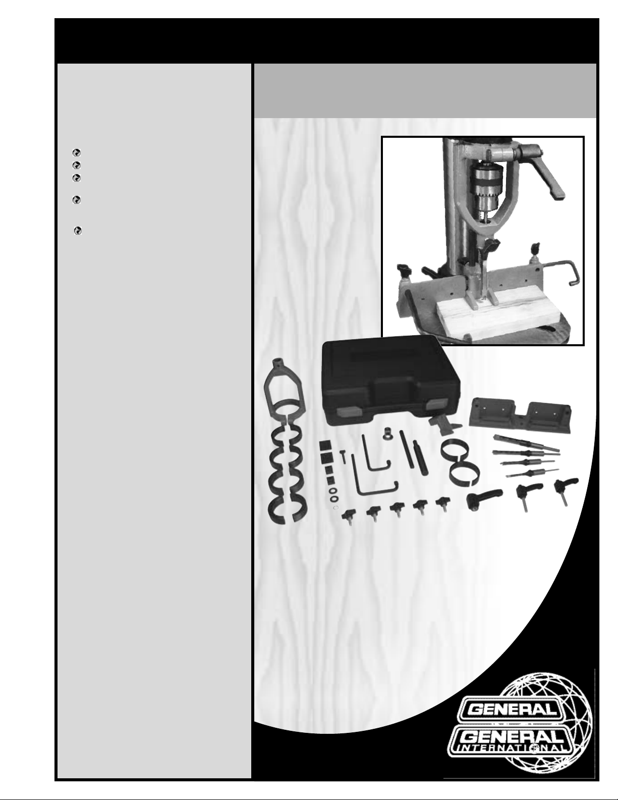
Convert almost any drill press into a
mortiser in minutes!
Supplied with a convenient storage case –
kit contains:
Mounting hardware
Cast-iron Chisel Holder
Guide fence with workipiece hold-
down
4 of the most commonly used morti-
sing chisel and bit sets with 5/8” bit
shank x 1/4”, 5/16”, 3/8” & 1/2”
Adapter hardware including 6 bushings (4 two-piece & 2 split style) to fit
most drill presses with 52, 55, 58, 60, 65 &
66 mm quills
SETUP & OPERATION MANUAL
MODEL
#70-905
MORTISING ATTACHMENT KIT
REVISION 1 - August 11/08
© Copyright General International 08/2008
Page 2

THANK YOU
for choosing this General®International model 70-905 Mortising
Attachment Kit. This Mortising Attachment Kit has been carefully tested and inspected before
shipment and if properly used and maintained, will provide you with years of reliable service.
To ensure optimum performance and trouble-free operation, and to get the most from your
investment, please take the time to read this manual before assembling, installing and operating the unit.
The manual’s purpose is to familiarize you with the safe operation, basic function, and features
of this Mortising Attachment Kit as well as the set-up and identification of its parts and components. This manual is not intended as a substitute for formal woodworking instruction, nor to
offer the user instruction in the craft of woodworking. If you are not sure about the safety of performing a certain operation or procedure, do not proceed until you can confirm, from knowledgeable and qualified sources, that it is safe to do so.
Once you’ve read through these instructions, keep this manual handy for future reference.
Disclaimer:
The information and specifications in this
manual pertain to the unit as it was supplied from the
factory at the time of printing. Because we are committed to making constant improvements, General
®
International reserves the right to make changes to
components, parts or features of this unit as deemed
necessary,without prior notice and without obligation to
install any such changes on previously delivered units.
Reasonable care is taken at the factory to ensure that
the specifications and information in this manual corres-
ponds with that of the unit with which it was supplied.
However, special orders and “after factory” modifications may render some or all information in this manual
inapplicable to your machine. Further, as several generations of this model of mortising attachment kit and several versions of this manual may be in circulation,if you
own an earlier or later version of this unit, this manual
may not depict your tool exactly.If you have any doubts
or questions contact your retailer or our support line with
the model number of your unit for clarification.
GENERAL® INTERNATIONAL
8360 Champ-d’Eau, Montreal (Quebec) Canada H1P 1Y3
Telephone (514) 326-1161 • Fax (514) 326-5555 • www.general.ca
Page 3

GENERAL®& GENERAL®INTERNATIONAL WARRANTY
All component parts of General®, General® International and Excalibur by General
International ® products are carefully inspected during all stages of production and each unit
is thoroughly inspected upon completion of assembly.
Limited Lifetime
Warranty
Because of our commitment to quality and customer satisfaction, General® and General®
International agree to repair or replace any part or component which upon examination,
proves to be defective in either workmanship or material to the original purchaser for the life
of the tool.
However, the Limited Lifetime Warranty does not cover any product used for professionnal or commercial production purposes nor for industrial or educational applications.
Such cases are covered by our Standard 2-year Limited Warranty only. The Limited Lifetime
Warranty is also subject to the “Conditions and Exceptions” as listed below.
Standard 2-Year Limited Warranty
All products not covered by our lifetime warranty including products used in commercial,
industrial and educational applications are warranted for a period of 2 years (24 months) from
the date of purchase. General® and General® International agree to repair or replace any
part or component which upon examination, proves to be defective in either workmanship or
material to the original purchaser during this 2-year warranty period, subject to the “conditions
and exceptions” as listed below.
T
o file a Claim
To file a claim under our Standard 2-year Limited Warranty or under our Limited Lifetime
Warranty, all defective parts, components or machinery must be returned freight or postage
prepaid to General® International, or to a nearby distributor, repair center or other location
designated by General® International. For further details call our service department at 1-888949-1161 or your local distributor for assistance when filing your claim.
Along with the return of the product being claimed for warranty, a copy of the original proof
of purchase and a “letter of claim” must be included (a warranty claim form can also be used
and can be obtained, upon request, from General® International or an authorized distributor)
clearly stating the model and serial number of the unit (if applicable) and including an explanation of the complaint or presumed defect in material or workmanship.
CONDITIONS AND EXCEPTIONS:
This coverage is extended to the original purchaser only. Prior warranty registration is not
required but documented proof of purchase i.e. a copy of original sales invoice or receipt
showing the date and location of the purchase as well as the purchase price paid, must be
provided at the time of claim.
Warranty does not include failures, breakage or defects deemed after inspection by General®
or General® International to have been directly or indirectly caused by or resulting from;
improper use, or lack of or improper maintenance, misuse or abuse, negligence, accidents,
damage in handling or transport, or normal wear and tear of any generally considered consumable parts or components.
Repairs made without the written consent of General® Internationallwill void all warranty.
Page 4

RULES FOR SAFE OPERATION
To help ensure safe operation, please take a moment to learn the machine’s applications and limitations, as well as potential hazards. General® International disclaims any real or implied warranty and holds itself harmless for any injury that
may result from improper use of its equipment.
1. Do not operate the drill press when tired, distracted, or
under the effects of drugs, alcohol or any medication
that impairs reflexes or alertness.
2. The working area should be well lit, clean and free of
debris.
3. Keep children and visitors at a safe distance when the
drill press is in operation; do not permit them to operate the drill press.
4. Childproof and tamper proof your shop and all
machinery with locks, master electrical switches and
switch keys, to prevent unauthorized or unsupervised
use.
5. Stay alert! Give your work your undivided attention.
Even a momentary distraction can lead to serious
injury.
6. Fine particulate dust is a carcinogen that can be haz-
ardous to health. Work in a well-ventilated area and
whenever possible use a dust collector and wear eye,
ear and respiratory protection devices.
7. Do not wear loose clothing, gloves, bracelets, neck-
laces or other jewelry while the drill press is in operation.
8. Be sure that adjusting wrenches, tools, drinks and
other clutter are removed from the machine and/or
the table surface before operating.
9. Keep hands well away from the bit and all moving
parts. Use a hold-down or clamp to secure the stock,
and use a brush, not hands, to clear away chips and
dust.
10. Be sure that the bit is securely installed in the chuck
before operation.
11. Be sure the bit has gained full operating speed before
beginning to drill.
12. Always use a clean, properly sharpened bit. Dirty or
dull bits are unsafe and can lead to accidents.
13. Use suitable work piece support if the work piece does
not have a flat surface.
14. Do not push or force the bit into the stock. The drill will
perform better and more safely when working at the
rate feed for which it was designed.
15. Avoid working from awkward or off balance positions.
Do not overreach and keep both feet on floor.
16. Keep guards in place and in working order. If a guard
must be removed for maintenance or cleaning be
sure it is properly re-attached before using the tool
again.
17. Never leave the machine unattended while it is run-
ning or with the power on.
18. Use of parts and accessories NOT recommended by
GENERAL® INTERNATIONAL may result in equipment
malfunction or risk of injury.
19. Never stand on machinery. Serious injury could result
if the tool is tipped over or if the bit is unintentionally
contacted.
20. Always disconnect the tool from the power source
before servicing or changing accessories such as bits,
or before performing any maintenance,cleaning, or if
the machine will be left unattended.
21. Make sure that the switch is in the “OFF” position before
plugging in the power cord.
22. Make sure the tool is properly grounded. If equipped
with a 3-prong plug, it should be used with a threepole receptacle. Never remove the third prong.
23. Do not use this drill press for other than its intended
use. If used for other purposes, GENERAL® INTERNATIONAL disclaims any real implied warranty and holds
itself harmless for any injury, which may result from
that use.
4
Page 5

UNPACKING
LIST OF CONTENTS QTY
CHISEL HOLDER .............................................................1
BUSHING SET (TWO PIECE)
– 52 MM ........................................................................1
– 55 MM.........................................................................1
– 58 MM.........................................................................1
– 60 MM.........................................................................1
STORAGE CASE..............................................................1
T-NUT (LARGE)................................................................2
T-NUT (SMALL) ................................................................2
FLAT WASHER..................................................................2
SPROCKET WASHER .......................................................1
T-SLOT BOLT ....................................................................1
HOLD DOWN ROD ........................................................1
KNOB..............................................................................5
STOP ROD ......................................................................1
5
BUSHING ........................................................................1
HOLD DOWN SHAFT ......................................................1
HOLD DOWN .................................................................1
ALIGNMENT PIN.............................................................1
BUSHING (SPLIT STYLE)
– 65 MM.........................................................................1
– 66 MM.........................................................................1
LOCKING LEVER (5/16” -18 INSERT) .............................1
FENCE.............................................................................1
CHISEL & BIT SET
– 1/4” .............................................................................1
– 5/16” ...........................................................................1
– 3/8” .............................................................................1
– 1/2” .............................................................................1
LOCKING LEVER (5/16” -18 BOLT)................................2
Carefully unpack and remove the mortising attachment kit and its components from the box and check for damaged or missing items as per the list of contents below.
NOTE: Please report any damaged or missing items to your General International distributor immediately.
Page 6

ASSEMBLY INSTRUCTIONS
1. Thread one of the knobs into the chisel holder
as shown .
ASSEMBLE THE CHISEL HOLDER
2. Slip the sprocket washer onto the T-slot bolt ,
then insert the T-slot bolt through the holder and
secure in place with the locking lever as shown .
1. Install the alignment pin in the chuck of your
drill press as shown in
.
FIT THE CHISEL HOLDER TO THE DRILL PRESS
2. Select the bushing – either two-piece for small to
medium drills or one-piece for large drills – that
matches the diameter of the quill of your drill press
.
3. Fit and hold the bushing onto the quill with the gap
facing front .
Note: You may have to adjust the height of the quill support to obtain a larger supporting surface for the bushing on the quill.
4. Fit the chisel holder assembly over the bushing as
shown in .
Note: Make sure to align the gaps in both the quill and the
chisel holder.
6
Page 7

7
5. Tighten the knob to hold the chisel holder in
place on the alignment pin, then secure the chisel
holder using the locking lever .
Note: Do not overtighten the locking lever – The gap does
not need to be closed .
6. Remove the alignment pin from the chuck.
1. Attach the fence to the table using the locking
levers, flat washers and either the large or small Tnuts as shown
.
ASSEMBLE THE FENCE AND SECURE IT TO THE DRILL PRESS TABLE
2. Attach the hold down shaft to the fence with its
flat face torwards the rear and secure with a
knob .
3. Attach the workpiece hold down to the hold
down shaft with another knob as shown. The
height of the hold down can be changed to suit
the height of the workpiece to approximately 4
1/2”.
4. Install the hold down rod and the stop rod as
shown, using 2 knobs .
Note: If needed, a shop made wooden auxiliary fence can
be attached to the fence face using screws through the
holes in the fence.
UNDERSIDE VIEW
4 1/2”
Page 8

1. Select the appropriate size chisel and bit.
INST
ALL A CHISEL AND BIT SET
2. Slip the bushing onto the bit as shown, .
4. To square the chisel to the workpiece, loosen the
knob and manually adjust the chisel .
Retighten the knob to secure.
1/2”
1/4”
5/16”
3/8”
3. Install the chisel and bit with the chip clearing slot
facing either left or right and tighten the bit in
the chuck.
NOTE: Position the bit in the chuck so that the tip of the bit
juts out approximately 1/16 " to 3/16 " from the tip of the
chisel .
CHISEL AND BIT TIP ARE VERY SHARP. TO AVOID PERSONAL INJURY PUT THE PLASTIC CAP BACK ON THE CHISEL AND BIT SET
BEFORE HANDLING OR INSTALLING IT ON THE DRILL PRESS.
Notes
8
Page 9

9
PARTS DIAGRAM
PARTS LIST
70-905
PART NO. REF. N0. DESCRIPTION SPÉCIFICATION QTY
70905-01 BUSHING (TWO PIECE) 58 MM 1
70905-02 BUSHING (TWO PIECE) 52 MM 1
70905-03 BUSHING (TWO PIECE) 55 MM 1
70905-04 BUSHING (TWO PIECE) 60 MM 1
70905-05 BUSHING (SPLIT STYLE) 65 MM 1
70905-06 BUSHING (SPLIT STYLE) 66 MM 1
70905-07 RATCHET HANDLE 5/16"-18 INSERT 1
70905-08 CHISEL HOLDER 1
70905-09 SPROCKET WASHER 1
70905-10 T-SLOT BOLT 1
70905-11 KNOB 5
70905-12 ALIGNMENT PIN 1
70905-13 HOLD DOWN 1
70905-14 HOLD DOWN SHAFT 1
70905-15 LOCKING LEVER 5/16"-18 BOLT 2
70905-16 FLAT WASHER 2
70905-17 FENCE 1
70905-18 STOP ROD 1
70905-19 HOLD DOWN ROD 1
70905-20 T-NUT (SMALL) 2
70905-21 T-NUT (LARGE) 2
70905-23 BUSHING 1
*70905-22
CHISEL & BIT SET
70-910 = 1/4”
70-920 = 5/16”
70-930 = 3/8”
70-940 = 1/2”
Page 10

IMPORTANT
When ordering replacement parts, always give the model number, serial number of the machine and
part number. Also a brief description of each item and quantity desired.
8360 Champ-d’Eau, Montreal (Quebec) Canada H1P 1Y3
Tel.: (514) 326-1161
Fax: (514) 326-5565 - Parts & Service / Fax: (514) 326-5555 - Order Desk
orderdesk@general.ca
www.general.ca
MODEL 70-905
 Loading...