

Page 1

SETUP & OPERATION MANUAL
FEATURES
10" TILTING ARBOR SAW
Quick release combination riving style
splitter and blade guard with anti-kickback
pawls and a second European style riving
knife also included.
Powder coated, scratch resistant, high
quality reinforced steel cabinet.
Large, heavy-duty cast-iron handwheels
for effortless blade adjustments.
High-precision General “T” Fence System
with 50” long guide rails, a melamine
extension table and adjustable support
legs (“Millenium Edition only”).
2 miter gauge T-slots and deluxe cast-iron
miter gauge.
Magnetic 2-step safety switch to prevent
unwanted or unintentional start-up is
equipped with an extra-large easy access
stop panel and a lock-out key to prevent
unauthorized use of the saw.
Powerful made in USA, totally enclosed,
fan cooled industrial motor.
Matching dual V-belt drive, on balanced
cast-iron pulleys for smooth vibration-free
running.
Arbor mounted on heavy-duty,
permanently lubricated, sealed ballbearings.
– LEFT TILT
SPECIFICATIONS
BLADE /ARBOR DIAMETER
10” (254 MM) / 5⁄8” (16 mm)
MAX. DEPTH OF CUT AT 90° / 45°
3 1⁄8” (79 mm)/ 2 1⁄8” (54 mm)
ARBOR TILT RANGE
0° À 45°
MAX. RIP TO LEFT / RIGHT OF BLADE
12” (305 mm) / 50” (1270 mm)
MAXIMUM DADO WIDTH
13⁄16” (21 MM)
DISTANCE AHEAD OF BLADE
12 3⁄4” (324 MM)
TABLE SIZE
28” X 36” X 34” (711 X 914 X 864 MM)
SIZE OF T-SLOTS
3⁄8” x 3⁄4” (10 x 19 mm)
ARBOR SPEED
4000 RPM
MOTOR
M2 3 HP, 230 V, 1 PH, 13.7 A
M3 3 HP, 230 V, 3 PH, 8.1 A
M4 3 HP, 208 V, 3 PH, 7.8 A
M5 3 HP, 600 V, 3 PH, 3 A
M6 3 HP, 440 V, 3 PH, 3.6 A
M25 5 HP, 230 V, 1 PH, 19.5 A
M35 5 HP, 230 V, 3 PH, 12 A
M45 5 HP, 208 V, 3 PH, 12 A
M55 5 HP, 600 V, 3 PH, 4.8 A
M65 5 HP, 440 V, 3 PH, 6 A
WEIGHT
495 LBS (225 KG)
(L x W x H)
MODEL
#650R-T50
REVISION 3 - June 23/11
© Copyright General®MFG / General® International 06/2011
Page 2

GENERAL® MFG (CO) LTD.
835, Cherrier Street, Drummondville (Quebec) Canada J2B 5A8
Telephone (514) 326-1161 • Fax (514) 326-5555 • www.general.ca
THANK YOU for choosing this General
®
MFG model 650R-T50 10" Tilting Arbor
Saw. This saw has been carefully tested and inspected before shipment and if properly used
and maintained, will provide you with years of reliable service. To ensure optimum performance and trouble-free operation, and to get the most from your investment, please take the
time to read this manual before assembling, installing and operating the unit.
The manual’s purpose is to familiarize you with the safe operation, basic function, and features
of this saw as well as the set-up, maintenance and identification of its parts and components.
This manual is not intended as a substitute for formal woodworking instruction, nor to offer the
user instruction in the craft of woodworking. If you are not sure about the safety of performing
a certain operation or procedure, do not proceed until you can confirm, from knowledgeable
and qualified sources, that it is safe to do so.
Once you’ve read through these instructions, keep this manual handy for future reference.
Disclaimer: The information and specifications in this
manual pertain to the unit as it was supplied from the
factory at the time of printing. Because we are committed to making constant improvements, General
reserves the right to make changes to components,
parts or features of this unit as deemed necessary, without prior notice and without obligation to install any
such changes on previously delivered units. Reasonable
care is taken at the factory to ensure that the specifications and information in this manual corresponds with
®
MFG
that of the unit with which it was supplied. However, special orders and “after factory” modifications may render
some or all information in this manual inapplicable to
your machine. Further,as several generations of this model of saw and several versions of this manual may be
in circulation, if you own an earlier or later version of this
unit, this manual may not depict your machine exactly.
If you have any doubts or questions contact your retailer or our support line with the model and serial number
of your unit for clarification.
Page 3

GENERAL®MFG & GENERAL®INTERNATIONAL WARRANTY
All component parts of General® MFG, General® International and Excalibur by General
International ® products are carefully inspected during all stages of production and each unit
is thoroughly inspected upon completion of assembly.
Limited Lifetime Warranty
Because of our commitment to quality and customer satisfaction, General® MFG and
General® International agree to repair or replace any part or component which upon examination, proves to be defective in either workmanship or material to the original purchaser
for the life of the tool. However, the Limited Lifetime Warranty does not cover any product used
for professionnal or commercial production purposes nor for industrial or educational applications. Such cases are covered by our Standard 2-year Limited Warranty only. The Limited
Lifetime Warranty is also subject to the “Conditions and Exceptions” as listed below.
Standard 2-Year Limited Warranty
All products not covered by our lifetime warranty including products used in commercial,
industrial and educational applications are warranted for a period of 2 years (24 months) from
the date of purchase. General® MFG and General® International agree to repair or replace
any part or component which upon examination, proves to be defective in either workmanship or material to the original purchaser during this 2-year warranty period, subject to the
“conditions and exceptions” as listed below.
To file a Claim
To file a claim under our Standard 2-year Limited Warranty or under our Limited Lifetime
Warranty, all defective parts, components or machinery must be returned freight or postage
prepaid to General® International, or to a nearby distributor, repair center or other location
designated by General® International. For further details call our service department at 1-888949-1161 or your local distributor for assistance when filing your claim.
Along with the return of the product being claimed for warranty, a copy of the original proof
of purchase and a “letter of claim” must be included (a warranty claim form can also be used
and can be obtained, upon request, from General® International or an authorized distributor)
clearly stating the model and serial number of the unit (if applicable) and including an explanation of the complaint or presumed defect in material or workmanship.
CONDITIONS AND EXCEPTIONS:
This coverage is extended to the original purchaser only. Prior warranty registration is not
required but documented proof of purchase i.e. a copy of original sales invoice or receipt
showing the date and location of the purchase as well as the purchase price paid, must be
provided at the time of claim.
Warranty does not include failures, breakage or defects deemed after inspection by General®
MFG or General® International to have been directly or indirectly caused by or resulting from;
improper use, or lack of or improper maintenance, misuse or abuse, negligence, accidents,
damage in handling or transport, or normal wear and tear of any generally considered consumable parts or components.
Repairs made without the written consent of General® Internationallwill void all warranty.
Page 4

TABLE OF CONTENTS
SAFETY RULES . . . . . . . . . . . . . . . . . . . . . . .5
ELECTRICAL REQUIREMENTS . . . . . . . . . . . . . .6
Electrical connections . . . . . . . . . . . . . . . . . . . . . . .6
Grounding instructions . . . . . . . . . . . . . . . . . . . . . . .6
Circuit capacity . . . . . . . . . . . . . . . . . . . . . . . . . . . . .6
Extension cords . . . . . . . . . . . . . . . . . . . . . . . . . . . . .6
IDENTIFICATION OF MAIN PARTS AND COMPO-
NENTS . . . . . . . . . . . . . . . . . . . . . . . . . . . .
BASIC FUNCTIONS . . . . . . . . . . . . . . . . . . . .8
UNPACKING . . . . . . . . . . . . . . . . . . . . . . . .8
List of contents . . . . . . . . . . . . . . . . . . . . . . . . . . . . . .8
Additional requirements for set up . . . . . . . . . . . . .8
PLACEMENT WITHIN THE SHOP / ESTABLISHING A
SAFETY ZONE . . . . . . . . . . . . . . . . . . . . . . . .
Connecting to a dust collector . . . . . . . . . . .15
BASIC ADJUSTMENTS AND CONTROLS . . . . . .15
Connecting to a power source . . . . . . . . . . . . . . .15
ON / OFF magnetic power switch . . . . . . . . . . . . .15
Overload protection . . . . . . . . . . . . . . . . . . . . . . . .16
Blade height adjustment . . . . . . . . . . . . . . . . . . . .17
Blade tilt (bevel) adjustment . . . . . . . . . . . . . . . . .17
OPERATING INSTRUCTIONS . . . . . . . . . . . . .17
7
Types of cuts . . . . . . . . . . . . . . . . . . . . . . .18
Ripping . . . . . . . . . . . . . . . . . . . . . . . . . . . . . . . . . . .18
Bevel ripping . . . . . . . . . . . . . . . . . . . . . . . . . . . . . .18
Ripping small work pieces . . . . . . . . . . . . . . . . . . .18
Cross cutting . . . . . . . . . . . . . . . . . . . . . . . . . . . . . . .19
Bevel cross cutting . . . . . . . . . . . . . . . . . . . . . . . . . .19
Adjusting and using the miter gauge . . . . . . .19
Adjusting the miter gauge . . . . . . . . . . . . . . . . . . .19
Adding an auxiliary fence to the miter gauge . .20
Miter cuts . . . . . . . . . . . . . . . . . . . . . . . . . . . . . . . . . .20
Compound miter cuts . . . . . . . . . . . . . . . . . . . . . . .20
9
CLEAN UP . . . . . . . . . . . . . . . . . . . . . . . . . .9
ASSEMBLY INSTRUCTIONS . . . . . . . . . . . . . .10
Install and adjust rails and fence . . . . . . . . .10
Attach the front fence rail . . . . . . . . . . . . . . . . . . . .10
Adjust the front rail height . . . . . . . . . . . . . . . . . . .10
Attach the back fence rail . . . . . . . . . . . . . . . . . . .11
Install and adjust riving knife . . . . . . . . . . . . . . . . . . . .11
Select a riving knife . . . . . . . . . . . . . . . . . . . . . . . . .11
Installation . . . . . . . . . . . . . . . . . . . . . . . . . . . . . . . .11
Removal . . . . . . . . . . . . . . . . . . . . . . . . . . . . . . . . . .12
Adjustment / Alignment . . . . . . . . . . . . . . . . . . . . .12
Setting the splitter/knife 90º to the table . . . . . . . .12
Setting the splitter/knife parallel to and centered
on the blade . . . . . . . . . . . . . . . . . . . . . . . . . . . . . .13
Remove / Install a saw blade . . . . . . . . . . . .13
Remove a saw blade . . . . . . . . . . . . . . . . . . . . . . .13
To install a saw blade . . . . . . . . . . . . . . . . . . . . . . .14
Using a dado head blade . . . . . . . . . . . . . . .21
MAINTENANCE . . . . . . . . . . . . . . . . . . . . . .21
Periodic maintenance . . . . . . . . . . . . . . . . . . . . . .21
Lubrication . . . . . . . . . . . . . . . . . . . . . . . . . . . . . . . .22
Adjusting the 90 º bevel stop . . . . . . . . . . . . . . . . .22
Adjusting the bevel angle pointer . . . . . . . . . . . .22
Adjusting the 45 º bevel stop . . . . . . . . . . . . . . . . .22
Recommended optional accessories . . . . .23
Parts list and diagrams . . . . . . . . . . .24 - 29
Contact information . . . . . . . . . . . . . . . . .30
Level the table insert . . . . . . . . . . . . . . . . . .14
Page 5

RULES FOR SAFE OPERATION
To help ensure safe operation, please take a moment to learn the machine’s applications and limitations, as well as
potential hazards. General® MFG disclaims any real or implied warranty and holds itself harmless for any injury that may
esult from improper use of its equipment.
r
1. Do not operate the saw when tired, distracted, or
nder the effects of drugs, alcohol or any medica-
u
tion that impairs reflexes or alertness.
2. The working area should be well lit, clean and free
of debris.
3. Keep children and visitors at a safe distance when
the saw is in operation; do not permit them to
operate the saw.
4. Childproof and tamper proof your shop and all
machinery with locks, master electrical switches
and switch keys, to prevent unauthorized or unsupervised use.
5. Stay alert! Give your work your undivided atten
tion. Even a momentary distraction can lead to serious injury.
6. Fine particulate dust is a carcinogen that can be
hazardous to health. Work in a well-ventilated area
and whenever possible use a dust collector and
wear eye, ear and respiratory protection devices.
7. Do not wear loose clothing, gloves, bracelets, neck-
laces or other jewelry while the saw is in operation.
Wear protective hair covering to contain long hair
and wear non-slip footwear.
8. Be sure that adjusting wrenches, tools, drinks and
other clutter are removed from the machine and/or
the feed table surface before operating.
9. Keep hands well away from the blade and all mo-
ving parts. Use a brush, not hands, to clear away
chips and dust.
10. Be sure that the blade is securely installed and in
proper cutting direction before operation.
11. Be sure the blade has gained full operating speed
before beginning to cut.
12. Always use a clean, properly sharpened blade.
Dirty or dull blades are unsafe and can lead to
accidents.
13. If using a power feeder, stop the feeder before stop-
ping the table saw.
15. Use suitable support when cutting stock that does
ot have a flat surface. Always hold stock firmly
n
against the fence when ripping, or against the miter
gauge when cross-cutting.
16. To minimize risk of injury in the event of workpiece
kickback, never stand directly in-line with the blade
or in the potential kickback path of the work piece.
17. Avoid working from awkward or off balance posi-
tions. Do not overreach while cutting; keep both
feet on floor. Never lean over or reach over the
blade and never pull the work piece over the blade
from behind. Use out feed support or have an assistant help when ripping long material.
18. Keep blade guards in place and in working order.
If a guard must be removed for maintenance or
cleaning, be sure it is properly reattached before
using the tool again.
19. Never leave the machine running with the power
on when not in operation.
20. Use of parts and accessories NOT recommended
by
GENERAL MFG
function or risk of injury.
21. Never stand on machinery. Serious injury could
result if the tool is tipped over or if the blade is unintentionally contacted.
22. Always disconnect tool from power before servicing
or changing accessories such as blades, or before
performing any maintenance, cleaning or adjustments, or if the machine will be left unattended.
23. Make sure that switch is in "OFF" position before
plugging in the power cord.
24. Make sure the tool is properly grounded. If equip-
ped with a 3-prong plug it should be used with a
three-pole receptacle. Never remove the third
prong.
25. Do not use this saw for other than its intended use. If
used for other purposes,
any real implied warranty and holds itself harmless
for any injury, which may result from that use.
may result in equipment mal-
GENERAL MFG
disclaims
14. Do not push or force stock into the blade. The saw
will perform better and more safely when working
at the rate for which it was designed.
5
Page 6
ELECTRICAL REQUIREMENTS
EFORE CONNECTING THE MACHINE TO THE POWER SOURCE, VERIFY THAT THE VOLTAGE OF YOUR POWER SUPPLY CORRESPONDS
B
ITH THE VOLTAGE SPECIFIED ON THE MOTOR I.D. NAMEPLATE. A POWER SOURCE WITH GREATER VOLTAGE THAN NEEDED CAN
W
RESULT IN SERIOUS INJURY TO THE USER AS WELL AS DAMAGE TO THE MACHINE. IF IN DOUBT, CONTACT A QUALIFIED ELECTRICIAN
EFORE CONNECTING TO THE POWER SOURCE.
B
HIS TOOL IS FOR INDOOR USE ONLY. DO NOT EXPOSE TO RAIN OR USE IN WET OR DAMP LOCATIONS.
T
NOTE: VOLTAGE REQUIREMENTS AND AMPERAGE DRAW FOR M3, M4, M5, M6, M25, M35, M45, M55 and M65 MOTORS
MAY NOT BE FULLY DESCRIBED IN THIS MANUAL. FOR COMPLETE ELECTRICAL REQUIREMENTS REFER TO THE MOTOR
I.D. NAME PLATE ON THE MACHINE. IF IN DOUBT CONSULT A LICENSED QUALIFIED ELECTRICIAN BEFORE PROCEEDING.
appropriate power cord and plug must be performed
by a qualified electrician. The machine must be connected to an electrical source using a power cord that
has a grounding wire, which must also be properly connected to the grounding prong on the plug. The outlet
must be properly installed and grounded and all electrical connections must be made in accordance with
all local codes and regulations.
CIRCUIT CAPACITY
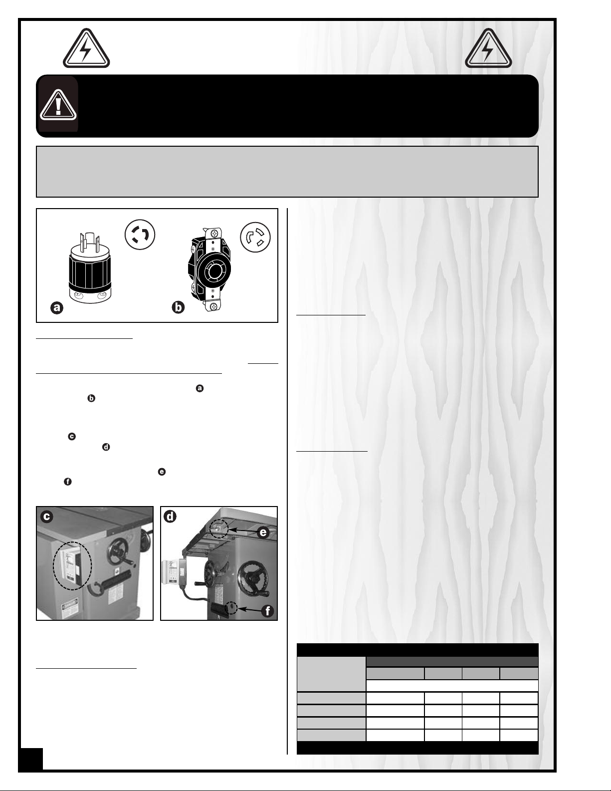
ELECTRICAL CONNECTIONS
Both a manual circuit breaker (or similar device) as well
as an electrical plug are recommended and should
be installed by a qualified electrician. Use locally
approved wire that includes a separate grounding wire
and a 3 prong grounding type plug with a matching
receptacle .
NOTE: To limit the potential for damage in transport, this
saw is shipped from the factory with the switch facing
inward . Before operating, the switch must be reinstalled
facing outward .
For added convenience, based upon personal preference,
a second mounting bracket, , and a second hole in the
base, , (for the power cord) allows installation of the
switch on the right side rather than the left side of the saw.
Make sure that the wires in your circuit are capable of
handling the amperage draw from your machine, as
well as any other machines that could be operating on
the same circuit. If you are unsure, consult a qualified
electrician. If the circuit breaker trips or the fuse blows
regularly, your machine may be operating on a circuit
that is close to its amperage draw capacity. However, if
an unusual amperage draw does not exist and a
power failure still occurs, contact a qualified technician
or our service department.
EXTENSION CORDS
The use of an extension cord is not generally recommended for 230V equipment. If you find it necessary,
use only 3-wire extension cords that have 3-prong
grounding plug and a matching 3-pole receptacle that
accepts the tool’s plug. Repair or replace a damaged
extension cord or plug immediately.
If you find it necessary to use an extension cord with
your machine make sure the cord rating is suitable for
the amperage listed on the motor I.D. plate. An undersized cord will cause a drop in line voltage resulting in
loss of power and overheating. The accompanying
chart shows the correct size extension cord to be used
based on cord length and motor I.D. plate amp rating.
If in doubt, use the next heavier gauge. The smaller the
number, the heavier the gauge.
GROUNDING INSTRUCTIONS
In the event of an electrical malfunction or short circuit,
grounding reduces the risk of electric shock to the operator. The motor of the “M2” model of this machine is
wired for 230V single phase operation. As with many
stationary industrial type machines, because each
installation situation is unique, this table saw is supplied
without a power cord or plug. The installation of an
6
TABLE - MINIMUM GAUGE FOR CORD
AMPERE
RATING
< 5
6 TO 10
10 TO 12
12 TO 16
* NR = Not Recommended
TOTAL LENGTH OF CORD IN FEET
230 VOLTS 50 FEET 100 FEET 200+ FEET
------->
------->
------->
------->
AWG
16 16 * NR
16 16 * NR
14 12 * NR
12 10 * NR
Page 7

10" TILTING ARBOR SAW – L
650R-T50
EFT TILT
IDENTIFICATION OF MAIN PARTS AND COMPONENTS
LEFT TABLE EXTENSION
MITER GAUGE
BLADE GUARD AND SPLITTER ASSEMBLY
TABLE INSERT
MAIN TABLE
FENCE
RIGHT TABLE EXTENSION
REAR RAIL
FRONT RAIL
BLADE TILT HANDWHEEL
BEVEL SCALE
DUST OUTLET
BLADE HEIGHT ADJUSTMENT HANDWHEEL
MAGNETIC SAFETY SWITCH
7
Page 8

BASIC FUNCTIONS
his cabinet saw has been designed for cutting solid wood as well as manufactured wood materials such as ply-
T
wood, wood panelling, particleboard, mdf and other wood based by-products. This saw is not designed for cutting
metals nor for cutting any materials other than wood or wood based stock.
This saw is designed for use with maximum 10" (254 mm) diameter blades having a center hole diameter of 5/8".
The blade can be raised to cut a maximum stock thickness of 3 1/8" with the blade set 90 degrees to the table. The
blade can be tilted up to 45 degrees to the left for bevel cuts to a maximum stock thickness of 2 1/8". Using any
standard aftermarket 8" diameter stacked dado blade set (not included), the maximum dado cutting capacity of
his saw is 13/16". Note: for safer dado cutting, an optional dado table insert (part number #650-3) can be purcha-
t
sed through your
To encourage safety through the proper use of either the supplied riving style splitter/blade guard assembly or the
European style riving knife the 650R saw has been designed with a quick install/quick release feature allowing the
user to install or remove either of these safety components in seconds.
General MFG/General
International distributor.
UNPACKING
Carefully unpack and remove the saw from the crate. All
other components and accessories are packed inside
the saw cabinet. Check for damaged or missing items as
per the list of contents below.
NOTE: Please report any damaged or missing items to
your General® International distributor immediately.
LIST OF CONTENTS QTY
SAW................................................................................1
SPLITTER /BLADE GUARD ASSEMBLY .............................1
EUROPEAN STYLE RIVING KNIFE ...................................1
ARBOR WRENCH ...........................................................1
MITER GAUGE ................................................................1
3/32" ALLEN KEY ............................................................1
5/32" ALLEN KEY ............................................................1
NOTE: F-42 rip fence and T-50 guide rails are packaged separately.
ADDITIONAL REQUIREMENTS FOR SET UP
• Phillips Screwdriver
• 1/2", 7/16" and 9/16" and open end wrench
• 1/8" Allen key
• Square
or
8
Page 9

PLACEMENT WITHIN THE SHOP /
3
6
1
/
4
”
36 1/4”
3
3
1
/
2
”
33 1/2”
8
4
”
84”
2
8
”
28”
2
1
3
/
4”
21 3/4”
2
1
3/
4
”
21 3/4”
ESTABLISHING A SAFETY ZONE
THIS MODEL 650R 10" TILTING ARBOR SAW IS VERY HEAVY. DO NOT OVER-EXERT. A HOIST OR FORKLIFT SHOULD BE USED TO LIFT
HIS MACHINE.
T
TO LIMIT THE RISK OF SERIOUS INJURY OR DAMAGE TO THE MACHINE, ANY EQUIPMENT USED TO LIFT THIS MACHINE SHOULD HAVE
RATED CAPACITY IN EXCESS OF 495 LBS (225 KGS).
A
PLACEMENT WITHIN THE SHOP
This machine should be installed and operated only on a
solid, flat and stable floor that is able to support the
weight of the saw (495 lbs - 225 kgs) and the operator.
Using the dimensions shown beside as a guideline, plan
for placement within your shop that will allow the operator to work unencumbered and unobstructed by foot traffic (either passing shop visitors or other shop workers) or
other tools or machinery.
ESTABLISHING A SAFETY ZONE
For shops with frequent visitors or multiple operators, it is
advisable to establish a safety zone around shop
machinery. A clearly defined “no-go” zone on the floor
around each machine can help avoid accidents that
could cause injury to either the operator or the shop visitor. It is advisable to take a few moments to either paint
(using non-slip paint) or using tape, define on the floor the limits or perimeter of each machines safety zone. Take
steps to ensure that all operators and shop visitors are aware that these areas are off limits whenever a machine is
running for everyone but the individual operating the unit.
CLEAN UP
The protective coating on the saw table prevents rust from
forming during shipping and storage. Remove it by rubbing with a rag dipped in kerosene, mineral spirits or
paint thinner. (Dispose of potentially flammable solventsoaked rags according to manufacturer’s safety recommendations.)
A putty knife, held flat to avoid scratching the surface,
may also be used to scrape off the coating followed by
clean-up with solvent. Avoid rubbing the saw’s painted
surfaces, as many solvent-based products will remove
paint.
To prevent rust, apply a light coating of paste wax or use
regular applications of any after-market surface protectant or rust inhibitor.
Tip: With a screw driver, push a solvent-saturated rag into
the T-slots to remove the grease.
9
Page 10
ASSEMBLY INSTRUCTIONS
For your convenience this saw is shipped from the factory partially assembled and requires only minimal assembly
and set up before being put into service. The left and right table extension wings are factory installed and aligned
nd unless seriously shaken or jolted in transport should not require further alignment.
a
If purchased with the standard General “T” Fence System, a full installation and operating instructions manual for
the fence system is supplied in the box with the “F-42” fence.
If purchased with the table board extension and support legs (Millennium Edition only) or if adding an aftermarket
table board and legs, installation instructions can also be found in the “F-42” fence manual.
ERIOUS PERSONAL INJURY COULD OCCUR IF YOU CONNECT THE MACHINE TO THE POWER SOURCE BEFORE YOU HAVE COMPLE-
S
TED THE INSTALLATION AND ASSEMBLY STEPS. DO NOT CONNECT THE MACHINE TO THE POWER SOURCE UNTIL INSTRUCTED TO DO
O.
S
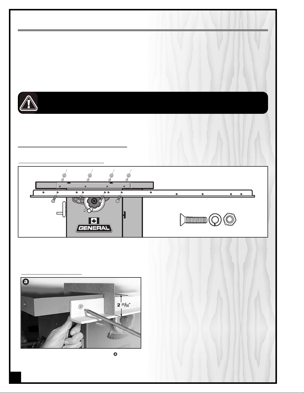
INSTALL AND ADJUST RAILS AND FENCE
ATTACH THE FRONT FENCE RAIL TO YOUR SAW
Refering to the diagram above, place 4 flat head countersunk screws, lock washers and nuts to assemble the front
rail to the front of the saw. But don’t tighten the nuts yet.
NOTE: The front rail, is the wider of the two rails and has holes in both faces.
ADJUST THE FRONT RAIL HEIGHT
Place the supplied L-jig on top of the table . Adjust the rail height until the bottom of the jig is flush with the rail shelf.
Hold the nuts firm with a 7/16" wrench and tighten the two screws on left and right ends of the rail. Tighten the center
screws only after double-checking rail height using the L-jig all along the rail and at both ends.
10
Page 11
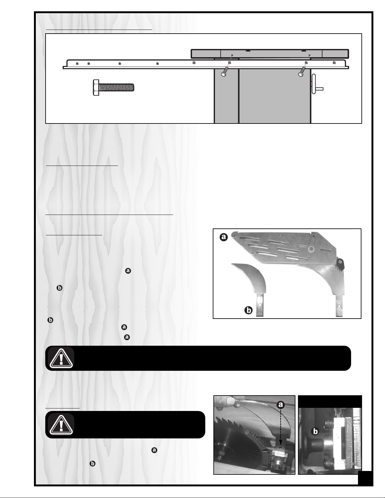
ATTACH THE BACK FENCE RAIL TO YOUR SAW
Refering to the diagram above, place hex. head bolts and where applicable lock washers and nuts to assemble
the rear rail to the back of the saw.
INSTALL AND ALIGN THE FENCE
Proceed to fence installation and alignment as per the instructions provided in your “F42” fence manual.
INSTALL AND ADJUST RIVING KNIFE
SELECT A RIVING KNIFE
Two riving knives are provided with this model 650R 10” tilting arbor saw:
- A combination riving style splitter and blade guard
with anti-kickback pawls ;
- A European style riving knife without blade guard
.
The riving knife must always be used with a blade guard.
If you already own an independently attached blade
cover such as our Excalibur 50-EXBC10, use the riving knife
. If you do not already own a blade cover, use the split-
ter/blade guard assembly
The riving knife/glade guard can be used with 9 3/4” to 10” maximum diameter blades.
THE BLADE MUST NEVER REMAIN EXPOSED WHEN USING THE SAW. TO PREVENT THE RISK OF SERIOUS INJURIES, ALWAYS
COVER THE BLADE WITH A BLADE COVER.
.
INSTALLATION
ALWAYS TURN OFF AND UNPLUG THE SAW BEFORE
INSTALLING THE RIVING KNIFE.
1. Fit the bottom end of the riving knife or splitter into
the slot in the mounting bracket and push down
ward until it bottoms out and clicks into place on the
locking pin .
TOP VIEW
11
Page 12

2. Test that the splitter/knife is locked into the housing
by pulling straight up on the knife or splitter. If properly locked in its socket, the splitter should not come out
until the locking pin is released
.
REMOVAL
LWAYS TURN OFF AND UNPLUG THE SAW BEFORE
A
REMOVING THE RIVING KNIFE.
PLATE REMOVED ONLY FOR
CLARITY
To remove the splitter/knife from its socket, pull the locking
pin toward you and pull the splitter/knife up and out of its
socket.
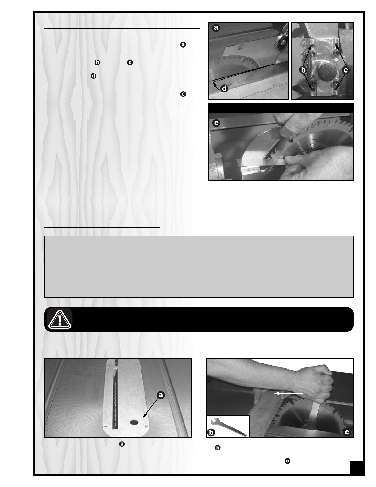
ADJUSTMENT / ALIGNMENT
TSIDE VIEWTVIEW FROM THE TOP
The splitter/knife mounting bracket consists of: a rocker arm
, a spacer , and a hold-down block . This assembly is
held together by four locking screws . Both 90º to the table
and parallel/centered to the blade alignments can be
achieved by adjusting the four set screws .
The locking screws must first be loosened (with the 5/32
allen key provided) – 1/4 turn or more, depending upon
how much adjustment is required, in order to be able to
adjust the set screws .
Tip: Tighten each locking screw immediately after adjusting its corresponding set screw to avoid undoing the previous adjustment
ALWAYS TURN OFF AND UNPLUG THE SAW BEFORE PERFORMING ANY ADJUSTMENTS.
SETTING THE SPLITTER/KNIFE 90º TO THE TABLE
1. With the blade set to 90º to the table, using a square,
verify the perpendicular alignment of the splitter/knife
to the table, .
2. If needed, loosen or tighten (with the 3/32 allen key
provided) the two upper and/or lower set screws
on the splitter/knife mounting bracket, until the splitter/knife is 90º to the table .
12
90º
Page 13
SETTING THE SPLITTER/KNIFE PARALLEL TO AND CENTERED ON THE
BLADE
1. Place a straightedge against the splitter/knife .
2. If needed, loosen or tighten one or both set screws
on both right and left side of the splitter/knife
mounting bracket until the splitter/knife is parallel
to the blade .
3. Use a feeler gauge to measure the clearance
between the straightedge and the blade . The
width of the gap must be more or less the same on
each side of the splitter/knife. If needed, re-adjust
the set screws on both right and left side of the splitter/knife mounting bracket to increase or decrea-
e the clearance between the straight edge and the
s
blade.
TABLE REMOVED FOR CLARITY ONLY
REMOVE / INSTALL A SAW BLADE
NOTE
This saw is intended for use with 10" (250mm) diameter or less saw blades having a center hole diameter of
5/8". There are many types of blades available to perform specific cutting jobs, such as crosscuts or ripping
only, or for use with plywood, panelling and other products. A good quality specialty blade can produce a
finer finish, be more efficient and place less strain on the saw. Use only saw blades designed for use at a maximum operating speed of 6000 RPM or less. Saw blades should be kept clean and sharp. Never store saw
blades by stacking them directly in contact with each other. Place a layer of cardboard or similar material
between the blades to keep them from coming into contact with each other.
BE SURE THE SAW IS UNPLUGGED AND COMPLETELY DISCONNECTED FROM THE POWER SOURCE WHENEVER INSTALLING OR
REMOVING A SAW BLADE!
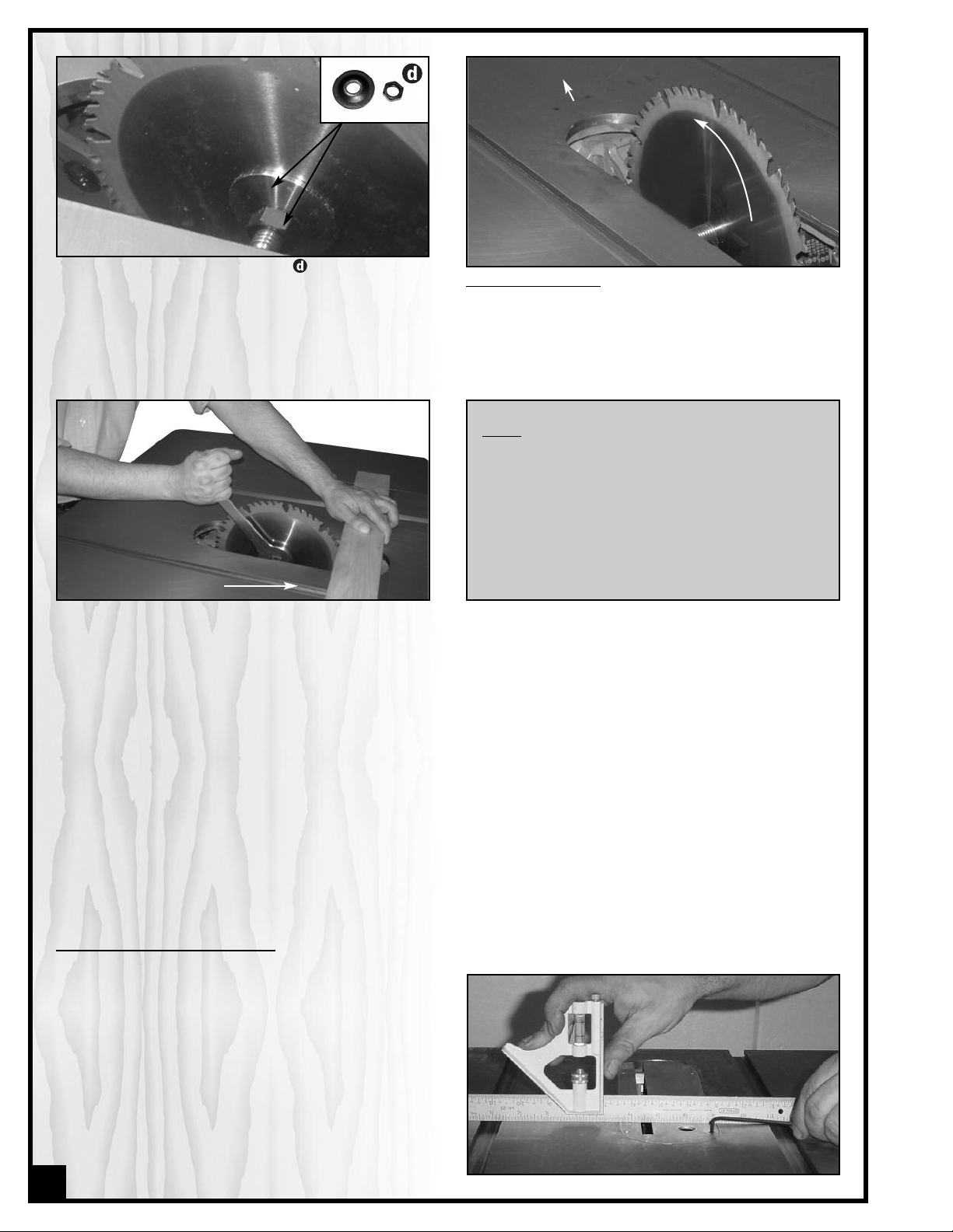
REMOVE A SAW BLADE
LOOSEN
1. Remove the table insert .
2. Holding the arbor with the arbor wrench provided
, wedge a block of wood between the teeth in
front of the saw and pull the arbor wrench toward
you or counter clockwise .
13
Page 14
FRONT
BLADE
DIRECTION
3. Remove the arbor nut & flange, , then remove the
blade.
TIGHTEN
2. Replace the flange and arbor nut. Holding the arbor
with the arbor wrench provided, wedge a block of
wood between the teeth at the rear of the saw and
push the arbor wrench away from you or clockwise.
3. Re-install the table insert.
TO INSTALL A SAW BLADE:
. Install the blade on the arbor so that the openings
1
between the teeth face the front of the saw (the
blade spins in the counter-clockwise direction).
NOTE
When tightening the arbor nut, take care not to
over tighten as this will make it very difficult to
remove later. Because the rotation of the blade
runs counter to the direction of the threads on the
nut, the blade is essentially tightening itself to the
nut whenever the saw is running. Though there are
no hard and fast rules for how much torque is
required, the arbor nut should always be tightened
firmly but without excess.
LEVEL THE TABLE INSERTLEVEL THE TABLE INSERT
Use a straightedge to determine whether the insert is level
with the table top. Turn each of the 4 adjusting screws with
a 1/8" Allen key until done.
Suggestion: Start by adjusting one rear screw and its
diagonal opposite in front, then tweak the remaining two
screws.
Note: If the sawblade has already been installed, use the raising handwheel to lower the blade below the table surface
before leveling the insert.
14
Page 15

CONNECTING TO A DUST COLLECTOR
S
T
O
P
• There is a 4” dust outlet located on the lower right of the
saw cabinet allowing for the connection to a dust col-
ection system (not included).
l
• Be sure to use appropriate size hose and fittings (not
included) and check that all connections are sealed
tightly to minimize airborne dust.
• If you do not already own a dust collection system
consider contacting your General® International distributor for information on our complete line of dust collection systems and accessories or visit our website at
www.general.ca
ALWAYS TURN ON THE DUST COLLECTOR BEFORE STARTING THE SAW AND ALWAYS STOP THE SAW BEFORE TURNING OFF THE
UST COLLECTOR.
D
BASIC ADJUSTMENTS & CONTROLS
CONNECTING TO A POWER SOURCE
TO AVOID RISK OF SHOCK OR FIRE DO NOT OPERATE THE UNIT WITH A DAMAGED POWER CORD OR PLUG. REPLACE DAMAGED CORD OR PLUG IMMEDIATELY.
Once the assembly steps have been completed, plug the
power cord into an appropriate outlet. Refer back to the
section entitled “ELECTRICAL REQUIREMENTS” and make
sure all requirements and grounding instructions are followed. When cutting operations have been completed
unplug the saw from the power source.
ON/OFF MAGNETIC POWER SWITCH
This model 650R is equipped with a Magnetic 2-step safety switch to prevent unwanted or unintentional startup and unauthorized use of the saw.
The switch assembly is equipped with a GREEN “START” button A, an extra-large easy access RED stop panel B, and
a lock-out key C.
To start the saw
the GREEN “START” button A.
To stop the saw
Once the RED “STOP”panel has been pressed, the saw can
only be started by pressing once again on the RED “STOP”
panel to release the green button, then by pressing on the
green button.
: Insert the lock-out key C and press on
: Press on the RED “STOP” panel, B.
A
C
B
TO PREVENT UNWANTED OR UNAUTHORIZED START-UP OR USAGE, REMOVE THE LOCK-OUT KEY AND STORE IT IN A SAFE PLACE, OUT
OF THE REACH OF CHILDREN, WHENEVER THE SAW IS NOT IN USE.
15
Page 16

OVERLOAD PROTECTION
S
TO
P
The magnetic safety switch on this saw is equipped with an overload protection feature. To prevent an electrical
overload from damaging the motor,in the event of a spike in line voltage or amperage draw, the internal overload
protector will automatically be tripped, thereby cutting off power to the motor.
Note: The most common causes of such overloads are:
1. Overworking the motor by attempting to feed thick dense workpiece material too quickly, thereby causing an
increase in power consumption and a spike in amperage draw.
2. An electrical extension cord that is too long or not the correct gauge of wire, which can also cause an increase
in amperage draw. If an electric extension cord must be used, follow the instructions and refer to the chart in
the electrical requirements section at the beginning of this manual.
3. Overworked circuit caused by operating on a circuit that is close to its amperage draw capacity. Make sure the
circuit being used is capable of handling the amperage draw from this machine as well as any other electrical
devices operating on the same circuit. If you are unsure, consult a qualified electrician.
To reset the overload protection switch after it has been
tripped proceed as follows:
1. Set the power switch on the saw to the off position
and disconnect the machine from the power source
Note: If the saw is permanently connected to a circuit
(hard-wired), set the wall panel circuit breaker or main
circuit interrupter to the off position.
,
.
SWITCH OFF
2. Unscrew the 2 screws and remove the control
box front cover
3. Press the blue reset button
.
, .
4. Reinstall the control box cover.
5. Reconnect the saw to the power source.
6. You can now resume cutting operations.
TO AVOID UNEXPECTED OR UNINTENTIONAL STARTUP, MAKE SURE THAT THE POWER SWITCH ON THE
SAW IS IN THE OFF POSITION BEFORE CONNECTING
TO A POWER SOURCE. .
16
Page 17

BLADE HEIGHT ADJUSTMENT
1/4”
1/4”
The blade height adjustment handwheel is located on the
front of the saw, , and there is a lock knob, , on the
handwheel that allows you to lock the wheel and secure
the blade at the desired height.
To raise or lower the blade:
1. Loosen the blade height lock knob, , by turning
counter clockwise.
2. To raise the blade:
To lower the blade:
clockwise.
. With the blade set to the desired height, tighten the lock knob, , by turning clockwise to lock the blade.
3
turn the handwheel, , clockwise.
turn the handwheel counter
TO LIMIT YOUR EXPOSURE TO THE BLADE AND ALSO TO MAXIMISE THE EFFECTIVENESS OF THE ANTI-KICKBACK
PAWLS (WHEN USING THE RIVING STYLE SPLITTER & BLADE GUARD), NEVER TAKE MORE BLADE HEIGHT THAN
IS REQUIRED TO COMPLETE THE CUT. WHEN SETTING THE BLADE HEIGHT FOR THROUGH-CUTS (CUTS ALL THE
WAY THROUGH THE THICKNESS OF A BOARD) SET THE HEIGHT OF THE BLADE TO ROUGHLY 1/4” HIGHER
THAN THE THICKNESS OF THE BOARD.
BLADE TILT (BEVEL) ADJUSTMENT
The blade tilt (bevel) adjustment handwheel is located on
the side of the saw, . The bevel locking knob, , is located on the handwheel and allows the user to lock the tilting mechanism and secure the blade at the desired
angle.
To change the angle of the blade:
1. Loosen the bevel locking knob, , by turning counter
clockwise.
2. Turn the handwheel, , left or right as required to set
the blade to the desired angle. The blade can be tilted to the left anywhere from 0° (90° to the table) to
45°.
3. With the blade tilted to the desired angle, tighten the bevel locking knob, , by turning clockwise to lock the
tilting mechanism and secure the blade.
OPERATING INSTRUCTIONS
VERIFY ALL CHECK POINTS BEFORE STARTING. FAILURE TO COMPLY CAN RESULT IN SERIOUS INJURIES.
• Make sure that the arbor nut is secure and that the blade is firmly tightened snug on the arbor.
• Check that the blade angle and height lock knobs are tight.
• If ripping, make sure the fence lock lever is engaged and that the fence is parallel to the blade.
• If cross cutting, make sure the miter gauge is locked tight.
• While using the saw, be sure to wear safety glasses at all times.
• Make sure that the blade guard/splitter assembly is properly installed and aligned with the blade, and that the
anti-kickback pawls are functioning.
17
Page 18

TYPES OF CUTS
RIPPING
Cutting a wood plank or sheet of plywood lengthwise to
reduce its width is called “ripping.” To rip stock, hold the
work with both hands pushing it into the blade as well as
firmly against the rip fence so that it is cut straight, .
The work to be cut must have a straight edge to ride
•
the fence and must be flat to make solid contact with
the table during the cut in order to avoid “kickback” (a
lade jam causing the wood to fly backwards and hit
b
you).
• Never rip or cut wood without using the fence or miter
gauge to guide it because the stock could kickback.
• Always use the blade guard and splitter assembly when cutting wood. It has anti-kickback fingers and a split
ter to prevent the saw “kerf” (the slit cut by the blade) from closing and binding the blade, which can overload
and/or stall the motor or cause the blade to lift and eject the workpiece towards the front of the saw at very
high speeds. The blade guard keeps your fingers away from the blade and also reduces the amount of saw
dust flying free.
• Although certain operations require the removal of the blade guard and splitter assembly, it should always be
replaced for regular cutting.
• Never stand in the line of the blade when ripping.
• Raise the saw blade only about 1/4” higher than the work to be cut.
As you complete the rip, the wood will either remain on the
table, tilt up to be caught on the end of the guard, or fall
onto the floor (or outfeed table). The waste part of the
stock remains on the table to be removed only after the
saw is stopped (unless it is large enough for immediate
safe removal).
If the work to be ripped is narrow, it is safer to use a push
stick, rather than the hands, to feed it into the blade, .
Push sticks with non-slip grippers can be purchased, but a
shop-made one works just as well.
When ripping extremely narrow stock that may not clear
the width of the blade guard, or very thin material such as
paneling, which may slip between the underside of the
fence and the table surface, a strip of wood as an auxiliary guide can be attached to the fence.
NEVER REACH IN TOWARDS THE BLADE WHILE THE BLADE IS STILL SPINNING! WHENEVER A RIP CUT IS COMPLET-ED, TURN OFF
THE SAW AND WAIT FOR THE BLADE TO COME TO A COMPLETE STOP BEFORE REACHING IN TO REMOVE THE WORKPIECE OR
THE WASTE MATERIAL.
BEVEL RIPPING
Bevel ripping is performed the same as ripping but with the saw blade set to an angle not perpendicular with the
table surface. After changing the bevel angle verify the alignment of the guard and splitter; make sure there is
clearance with the saw blade.
RIPPING SMALL WORK PIECES
Do not attempt rip cuts if the work piece is too small, as this will oblige you to place your hands too close to the
blade and put you at serious risk of injury. When ripping narrower widths; use a push block or a push stick in order
to avoid placing hands near the blade.
18
Page 19

CROSS CUTTING
Cutting against the grain, to shorten the length of a board
is crosscutting. With some smaller-sized and rectangular
pieces, you often have the choice of ripping or crosscutting. Always use the miter gauge, , when crosscutting;
never cut a piece unsupported. The miter gauge may be
sed in either slot, but most operators prefer the left
u
groove for typical work. When the blade is tilted for bevel
cutting, use the table slot that does not cause interference
with your hand or the saw blade guard.
To begin crosscutting, place the work on the miter gauge
and, with the motor OFF, slide it up close to the blade to
lign the outer edges of the teeth with your cut mark, .
a
Keep a firm grip as you pull the miter gauge and the
wood back away from the blade. Lower the blade guard,
turn on the saw and make the cut. When the work is cut
through, move one or both cut pieces — if long enough
to handle without danger — immediately off to the side,
away from the turning blade. Turn off the motor.
BEVEL CROSS CUTTING
This procedure is the same as cross cutting except that the blade is set to an angle other than 0. After changing the
bevel angle, verify the alignment of the guard and splitter and verify that there is clearance with the saw blade.
ADJUSTING AND USING THE MITER GAUGE
ADJUSTING THE MITER GAUGE
The miter gauge supplied with your saw has accurately adjusted
index stops at 90° and 45° to the right and left, with a 30° maximum.
To use a setting other than 90°, loosen the lock knob, , by turning
it counter-clockwise,flip down the stop-lock tab, , rotate the miter
head to 45°, or any angle shown on the numerical guide. Turn the
lock knob clockwise to tighten it.
To check the accuracy of the miter gauge’s factory settings, set it at
90° and check it with an L-square or T-square. To verify the setting,
make a test cut in scrap stock and then use a square to check the
cut piece.
If the miter gauge needs adjusting, manually turn the head so the
pointer is where you think it ought to be, tighten the lock knob and
loosen the nut, . Turn the adjusting screw until it touches the stoplock tab. Tighten down the nut. Recheck the angle by making
another test cut. Repeat, if necessary, until a true 90° is achieved.
19
Page 20

ADDING AN AUXILIARY FENCE TO THE MITER GAUGE
To ensure a true 90° crosscut, especially with longer pieces of wood
that need more support than the narrow miter gauge head can
provide, an auxiliary wood fence can be attached.
Make sure the wood for the fence is straight, not bowed. It should
be about 2 inches wide and extend about 12 inches from either
side of the miter head. Drill 2 holes in the wood corresponding to
those on the miter head and use bolts and nuts to secure the wood
fence to the head, .
To use the miter gauge with an auxiliary fence, first notch the fence with the saw blade a bit higher than the workpiece, . Measure and draw a cutline on your wood, , then place it on the miter fence. Position your cutline
against the notch. Turn on the saw, slide the work up until it is cut through (but don’t cut off the fence).
Marking Wood. If you measure a cut for 24 inches, line up the blade on the waste side of the mark. Don’t cut
through the middle of the measurement line or you’ll reduce your desired board length by half the width of the saw
blade! For accurate work, don’t mark your cut with a fat pencil line, . A narrow dash, with a sharp pencil point is
best, . Encircle the dash so you’ll find it again and add a small X to indicate the waste or cut-off side . Pencils,
like saw blades, have thickness. When squaring off from the cut mark, align your square to allow for pencil clearance, which will be about 1/16” away from the drawing edge of the square, .
ARGER VIEW
L
FRONT VIEW
MITER CUTS
This operation is the same as cross cutting, except the
miter gauge is set to an angle other than 0. Hold the work
piece firmly against the miter gauge and feed the work
piece slowly into the blade to prevent it from moving
during the cut.
COMPOUND MITERING
This is a combination of bevel cross cutting and mitering. It is infrequently used. Follow instructions for both bevel cutting and mitering.
20
Page 21

USING A DADO HEAD BLADE
Dadoing is cutting a “rabbet” or a wide groove into the
work. A dado blade, , (not supplied with your saw) usually consists of two outer blades and several interior cutters. These can be adjusted to cut grooves from 1/8” to
13/16” for making shelves, joints and tenoning. Set the
blade’s width according to the instructions supplied with
your dado blade.
After adjusting its width, mount the dado blade on your
saw just like a regular blade. You’ll need an optional
dado insert, , (Item # 650-3) to replace the standard one
hat comes with your saw. Use the fence to line up the cut.
t
The blade guard/splitter must be removed when dadoing. Never use the dado blade in a bevel position.
LWAYS VERIFY THE DADO BLADE CLEARANCE BEFORE CONNECTING THE SAW TO THE POWER SOURCE. REATTACH THE
A
GUARD AND VERIFY & ADJUST SPLITTER/RIVING KNIFE ALIGNMENT IF NEEDED. AFTER DADO CUT IS FINISHED. THE MAXIMUM
DADO HEAD WIDTH FOR THIS SAW IS 13/16” AND THE MAXIMUM DADO BLADE DIAMETER IS 8”.
MAINTENANCE
MAKE SURE THE SAW HAS BEEN TURNED OFF AND UNPLUGGED FROM THE POWER SOURCE BEFORE PERFORMING ANY
MAINTENANCE.
PERIODIC MAINTENANCE
• Inspect/test the ON/OFF switch before each use. Do not operate the saw with a damaged switch - replace a
damaged switch immediately
• Inspect the saw blade for damage or chipped teeth before each use. Replace a damaged or chipped blade
immediately. Never operate the saw with a damaged or chipped blade
• Keep the saw table clean and free of dust, pitch or glue.
• An occasional light coating of paste wax can be used to protect the cast-iron surface. Ask our local distributor for suggestions on table top cleaners and cast-iron surface protection based on what is readily available
in your area.
• Occasionally open the cabinet door and brush off and vacuum out accumulated dust from inside the cabinet and on the blade tilting gears and on or around the motor.
• Periodically inspect the power cord and plug for damage. To minimize the risk of electric shock or fire, never
operate the saw with a damaged power cord or plug. Replace a damaged power cord or plug at the first
sign of damage.
• To minimize airborne dust particles periodically inspect all dust collection fittings – re-tighten as needed.
21
Page 22

LUBRICATION
Keep the blade tilt mechanism as well as the blade height
adjustment mechanism well lubricated and free of dust or
debris. Clean and remove dust, debris, and old lubricant
as needed depending on frequency of use. After cleaning,
reapply lubricant as needed.
Note: To lubricate the blade tilt mechanism , apply a
very light dab of any all-purpose grease (available at any
hardware store).
To lubricate the blade height adjustment mechanism ,
loosen and remove the lock knob on the blade tilt adjustment hand wheel, then spray some dry lubricant into the
hole .
The motor and all bearings are sealed and permanently lubricated – no further lubrication is required. No other
part of this table saw needs lubrication.
ADJUSTING THE 90° BEVEL STOP
1. Disconnect the machine from the power source.
2. Raise the blade to its highest position and lift the blade
guard.
3. Loosen the bevel lock knob and turn the blade tilting
handwheel clockwise until it stops.
4. Verify the 90° angle of the blade with a square from the
left side of the blade . Keep the square flat against
the table and against the flat part of the blade - Do not
touch the teeth of the blade.
If the blade angle is incorrect, adjust the 90° stop screw,
, located inside the cabinet, on the left side of the saw.
Proceed as follows:
5. Loosen the jam-nut using a 1/2" open end wrench.
6. Adjust the height of the 90° stop screw, , until the
blade is 90° to the table when the 90° stop screw
touches the stop .
7. Re-tighten the jam-nut.
ADJUSTING THE BEVEL ANGLE POINTER
The bevel pointer should read“0”when the blade is at 90°
to the table. If not, with the blade set 90° vertical to the
table, remove the hand wheel by loosening the hand
wheel lock knob, , then loosening the set screw on the
shaft of the hand wheel,
the hand wheel has been removed, loosen the screw,
on the pointer mounting bracket and manually align the
pointer,,with the zero on the bevel scale, then re-tighten
the screw and re-attach the hand wheel.
, with the 5/32" Allen key. Once
ADJUSTING THE 45° BEVEL STOP
Verify the 45° setting by tilting the blade as far as possible to
the left and using a square to check the angle . If needed adjust as for the 90° stop, this time using the stop screw
inside the cabinet, at the front of the saw, .
LARGER VIEW
,
22
Page 23

RECOMMENDED OPTIONAL ACCESSORIES
We offer a large variety of products to help you increase convenience,productivity,accuracy and safety when
using your saw Here’s a small sampling of optional accessories available from your local General International
dealer.
For more information about our products, please visit our website at www.general.ca
Excalibur by General
International Osborne
miter guide – #50-EB3
Quickly and easily finds any
angle. Rock solid triangular
design is reversible for use on
either side of the blade.
Adjustable fence for tight
blade clearance, telescoping fence extension and
sliding flip up stop for accurate repeat cuts. A “must
have” for any serious hobbyist.
Tenoning Jig
#50-050
Solid cast iron. Fits left or right tilt
saws for safe and accurate
tenoning.
Micro-adjustment attachment for General T-Fence
#50-055
Fits General MFG F-36 Home
shop and F-42 Industrial TFence. Large, ergonomic adjustment handle. Easy to
install clamp-on design and
quick flip up magnetic engage/disengage. For precision fence adjustments – no
more tapping the fence by
hand.
Excalibur by General
International Overarm
Blade Cover – With Dust
Collection Capability –
#50-EXBC10
Maximize dust collection efficiency with any dust collec-
tor without compromising
safety. 4” main boom with 3” inner boom. Easy to install
and simple to use. See-through blade cover with spring
loaded swing arm raises and lowers to suit stock thickness.
Unique design mounting bracket: pivots away or removes
completely in seconds.
Dado insert
#650-3
Fits left tilt model 650R only, for
use with dado blades up to
13/16” maximum width.
Dust Collector
We have a wide selection of
dust collectors to suit all your
shop needs. Dust collectors
contribute to a cleaner and
more healthful workshop environment.
Zero Clearance insert
#50-060
Eliminates space between
the blade and insert to help
reduce tear-out and airborne dust. Raise the blade
through the insert and custom cut to your blade kerf.
Heavy-Duty Mobile base for Table
Saw # 50-030
900 lbs load capacity! Designed specifically for use with
table saws that are equipped with extension tables & support legs.
23
Page 24

1
3
4
5
17
30
21
25
28
27
24
53
59
57
29
58
35
44
9
1
4
42
51
41
43
9
52
46
43
45
47
48
49
50
54
39
37
40
38
36
27
25
26
12
13
11
15
16
20
22
23
21
24
17
14
19
18
1
2
4
5
32
31
9
10
6
8
7
28
25
27
9
24
10
8
7
6
27
25
24
34
33
11
13
31
55
56
61
60
MECHANISM
*
24
manufacturer.
are subject to the approval of the motor
motor manufacturer. Warranty claims for motors
*Note: Motors are warranted for one (1) year by the
Page 25

PARTS LIST
50R
6
REF. N0. PART N0. DESCRIPTION SPECIFICATION QTY
1 P-6 HEX. HEAD BOLT 3/8-16 UNC X 1 1/2 5
2 654-1 FRONT TRUNION 1
3
4 P-15 LOCK WASHER 3/8" 5
5 P-17 NUT 3/8-16 UNC 4
6 354-12SA LOCK KNOB ASSEMBLED 2
7 354-15 HANDLE PIN 2
8 P-332 HANDLE 354-14 2
9 P-7 ALLEN SET SCREW 5/16-18 UNC X 5/16" 4
10 354-9SA HANDWHEEL ASSEMBLY 2
11 354-23 KEY 2
2 354-7 ELEVATING SHAFT 1
1
13 354-13 GUIDE PIN 4
14 354-8 MAIN BEARING 1
15 P-100 HEX. HEAD BOLT 5/16"-18 UNC X 3/4" 2
16 P-51 LOCK NUT 5/16-18 UNC 2
17 P-35 HEX. HEAD BOLT 3/8"-16 UNC X 1" 6
18 P-116 TAPPING-SCREW 8-32 UNC X 3/8 1
19 354-17 POINTER 1
20 654-2 FRONT TILT TRUNNION 1
21 P-111 SPRING PIN 1/4 X 3/4 4
22 P-305 HEX. HEAD BOLT 5/16"-18 UNC X 1 1/2" 2
23 P-135 LOCK WASHER 5/16" 4
24 P-70 COPPER BEARING SS-2428-12 4
25 P-126 SPRING PIN 3/16" X 1 1/4" 4
26 554-23 LEFT WORM 1
27 P-77 FIBER WASHER 3/4 X 1 1/4 X 1/32 4
28 354-6 COLLAR 2
29 654 CHUTE 1
30 654-3 REAR TILT TRUNNION 1
31 P-99 HEX. HEAD BOLT 5/16" -18 UNC X 1" 8
32 354-11 FLANGE 1
33 354-10 TILT SHAFT 1
34 354-5 RIGHT GEAR 1
35 653 ARBOR BRACKET 1
36 354-22 KEY 1
37 P-304 HEXAGONAL SOCKET HEAD CAP SCREW 5/16-18 UNC X 1" 1
38 354-21 KEY 1
39 654-19A MOTOR BASE 1
40 354-20 PIN 1
41 P-106 HEXAGONAL LOCK NUT 5/8-18 UNC 1
42 P-108 SNAP RING N-1308-168 2
43 P-279 BEARING 6203-2RS 2
44 353-3 ARBOR PULLEY 1
45 P-4 WOODRUFF KEY #9-3/16" X 3/4" 1
46 353-5B LARGE SPACER 1
47 653-1ASS ARBOR WITH FLANGE AND NUT 1
48 P-1029 CARBIDE COMBINATION BLADE 9.840" - 50 TEETH 1
49 353-2 CURVED WASHER 1
50 653-6 ARBOR NUT (RIGHT-HAND THREAD) 5/8-10 ACME 29 DEGREES 1
51 P-1217 BELT (3 HP) A-24 26" LONG 2
51 P-273 BELT (5 HP) A-23 2
52 353-8 MOTEUR PULLEY(STANDARD) 7/8" 1
53 353-7 ARBOR WRENCH 1
54 354-24 MOTOR SPACER 2
55 55 P-1084 FLAT WASHER 5/16" 4
56 56 P-182 NUT 5/16-18 UNC 4
57 657 MOUNTING BRACKET ASSEMBLY (650) 1
58 58 357-33 GUIDE PIN 1
59 59 P-308 OUTER HOLD-DOWN RING SÉRIE R3100-200 1
654-4 REAR TRUNION 1
MECHANISM
25
Page 26

MECHANISM
3
1
4
6
7
8
2
5
PARTS LIST
REF. N0. PART N0. DESCRIPTION SPECIFICATION QTY
60 85-240 MAGNETIC SAFETY SWITCH (230 V, 1 PH, 13.7 A)
85-255 MAGNETIC SAFETY SWITCH (230 V, 3 PH, 8.1 A)
85-255 MAGNETIC SAFETY SWITCH (208 V, 3 PH, 7.8 A)
85-610 MAGNETIC SAFETY SWITCH (600 V, 3 PH, 3 A)
- MAGNETIC SAFETY SWITCH (440 V, 3 PH, 3.6)
5-285 MAGNETIC SAFETY SWITCH (230 V, 1 PH, 19.5 A)
8
85-255 MAGNETIC SAFETY SWITCH (230 V, 3 PH, 12 A)
85-255 MAGNETIC SAFETY SWITCH (208 V, 3 PH, 12 A)
85-620 MAGNETIC SAFETY SWITCH (600 V, 3 PH, 4.8 A)
- MAGNETIC SAFETY SWITCH (440 V, 3 PH, 6 A)
61 M-100* MOTOR (M2) 3 HP, 230 V, 1 PH, 13.7 A 1
M-106* MOTOR (M3) 3 HP, 230 V, 3 PH, 8.1 A 1
M-106* MOTOR (M4) 3 HP, 208 V, 3 PH, 7.8 A 1
M-107* MOTOR (M5) 3 HP, 600 V, 3 PH, 3 A 1
M-106* MOTOR (M6) 3 HP, 440 V, 3 PH, 3.6 A 1
M-173* MOTOR (M25) 5 HP, 230 V, 1 PH, 19.5 A 1
M-174* MOTOR (M35) 5 HP, 230 V, 3 PH, 12 A 1
M-174* MOTOR (M45) 5 HP, 208 V, 3 PH, 12 A 1
M-175* MOTOR (M55) 5 HP, 600 V, 3 PH, 4.8 A 1
M-174* MOTOR (M65) 5 HP, 440 V, 3 PH, 6 A 1
FOR M2 MOTOR
FOR M3 MOTOR
FOR M4 MOTOR
FOR M5 MOTOR
FOR M6 MOTOR
FOR M25 MOTOR
FORM 35 MOTOR
FOR M45 MOTOR
FOR M55 MOTOR
FOR M65 MOTOR
1
1
1
1
1
1
1
1
1
1
TABLE
*Note: Motors are warranted for one (1) year by the motor manufacturer. Warranty claims for motors are subject to the
pproval of the motor manufacturer..
a
26
PARTS LIST
REF. N0. PART N0. DESCRIPTION SPECIFICATION QTY
1 651 MAIN TABLE (1.562 X 20 X 27.937) 1
2 650-2R TABLE INSERT 1
3 351-1 EXTENSION (LEFT AND RIGHT) (1.476 X 8 X 27.937) 2
TABLE
4 P-93 HEX HEAD BOLT 7/16-14 UNC X 1'' 6
5 650-3 DADO INSERT (OPTIONAL – NOT INCLUDED) 1
6 P-528 SOCKET HEAD CAP SCREW 7/16-14 UNC X 3/4'' 4
7 352-11 SWITCH BRACKET 1
8 P-101 HEX HEAD BOLT 3/8-16 UNC X 5/8'' 2
Page 27

CABINET
PARTS LIST
REF. N0. PART N0. DESCRIPTION SPECIFICATION QTY
1 662 RIGHT SIDE PANEL 1
2 362-10 CABINET DOOR WITH MOTOR 3 HP 1
3 662-14 FRONT BOTTOM PANEL 1
4 662-15 BACK BOTTOM PANEL 1
5 P-88 HEX. HEAD CAP SCREW 1/4" - 20 X 1/2" 1
6 P-1063 HINGE CABINET 350 2
7 P-1066 RUBBER LATCH 1
8 P-1177 POP RIVET 1/8" X .265 X .125 2
9 P-1194 HEX HEAD CAP SCREW 6 MM X 8 MM 2
10 P-1196 GENERAL MILLENNIUM PLATE 1
11 P-120 TAPPING SCREW 8-32 X 1/4" 2
12 P-136 LOCK WASHER 1/4" 1
13 P-212 JAM NUT 202-135 1
14 P-529 SCALE 352-7 1
CABINET
27
Page 28

3
2
1
SPLITTER / BLADE GUARD ASSEMBLY – RIVING KNIFE
1
8
17
16
15
1
4
1
3
12
4
9
8
6
5
7
1
1
10
28
26
2
7
2
4
25
2
2
23
20
2
1
1
9
29
PARTS LIST
REF. N0. PART N0. DESCRIPTION SPECIFICATION QTY
1 657 MOUNTING BRACKET ASSEMBLY (650) 1
2 657-21 RIVING KNIFE 1
3 650-7R SPLITTER/BLADE GUARD ASSEMBLY 1
4 657-24 SPLITTER 1
5 P-221 ROUND HOOK 4
6 357-29 WASHER 4
7 357-25 GUARD ARM 2
8 357-28 MIDDLE WASHER 1
9 357-15 GUARD ASSEMBLY 1
10 357-26 ANTI-KICKBACK PAWL 2
11 P-208 GROOVED PIN 3/16 "X 3/4" 1
12 P-445 SPUR SPRING 357-12A 1
13 357-30 GUARD PIN 1
14 P-166 NYLON WASHER .062 X 5/16I.D.X 7/8 O.D. 2
15 357-31 GUARD PIVOT 1
16 357-32 ANTI-KICKBACK PAWL PIN 1
17 P-203 FLAT WASHER #8,.062 X 3/16 I.D. X 1/2 O.D. 1
18 P-116 ROUND HEAD MACHINE SCREW, SQUARE GRIP #2,#8-32 UNF X 3/8 1
19 657-20 ROCKER ARM (650) 1
20 357-22 ADJUSTMENT SPACER 1
21 P-152 SET SCREW 0-32 X .375 14
22 P-312 CAP SCREW 10-24 X 3/4 1
23 P-140 COMPRESSION SPRING 1
SPLITTER / BLADE GUARD ASSEMBLY – RIVING KNIFE
28
24 357-23 HOLD-DOWN BLOCK 1
25 P-496 LOCK WASHER 3/16 4
26 P-395 CAP SCREW 10-32 X 3/4 4
27 P-449 KNOB 1
28 P-308 OUTER HOLD-DOWN RING SÉRIE R3100-200 1
29 P-717 GUIDE PIN 1
Page 29

3
2
1
7
6
9
8
10
15
13
14
5
4
16
11
12
MITER GAUGE ASSEMBLY– PART # 350-5
PARTS LIST
REF. N0. PART N0. DESCRIPTION SPECIFICATION QTY
1 359-3 GUIDE BAR 1
2 359-4 GUIDE WASHER 1
3 P-168 FLAT HEAD SCREW 1/4-20 UNC X 3/8" 1
4 359-5 PIVOT 1
5 2561 LOCK STUD 1
6 3564 STOP 1
MITER GAUGE
7 P-144 GROOVE PIN TYPE-2, 1/8" X 1/4" 1
8 J-80-25 POINTER 1
9 P-218 SOCKET HEAD SCREW 10-32 UNF X 1/4 1
10 359-1 MITER GAUGE 1
11 P-442 ANGLE SCALE 1
12 P-329 DRIVE SCREW #4 X 1/4" 4
13 P-81 SOCKET SCREW 10-32 UNF X 5/8 3
14 P-498 STOP NUT #10-32 UNF 3
15 P-443 HANDLE 1
16 P-443 FLAT WASHER 5/16" 1
29
Page 30

MODEL 650R-T50
835, Cherrier Street, Drummondville (Quebec) Canada J2B 5A8
Tel.: (514) 326-1161
Fax: (514) 326-5565 -
Parts & Service / Fax: (514) 326-5555 - Order Desk
orderdesk@general.ca
www.general.ca
IMPORTANT
When ordering replacement parts, always give the model number, serial number of the machine and
part number. Also a brief description of each item and quantity desired.
 Loading...