

Page 1
SETUP & OPERATION MANUAL
RIVING KNIFE CONVERSION /
RETROFIT KIT
For General MFG model 650 left-tilt saw.
Kit contains all parts and components to retro-
fit /convert a non-riving knife model 650, 3HP*
saw to the new type 650R saw with riving style
(raises and lowers with the blade) splitter /
blade guard assembly with anti-kickback
pawls and a European style “true” riving knife
- both included with kit.
*Note for 5 HP motors, modifications to the
motor shaft will be required - contact our
technical service or your local distributor for
details.
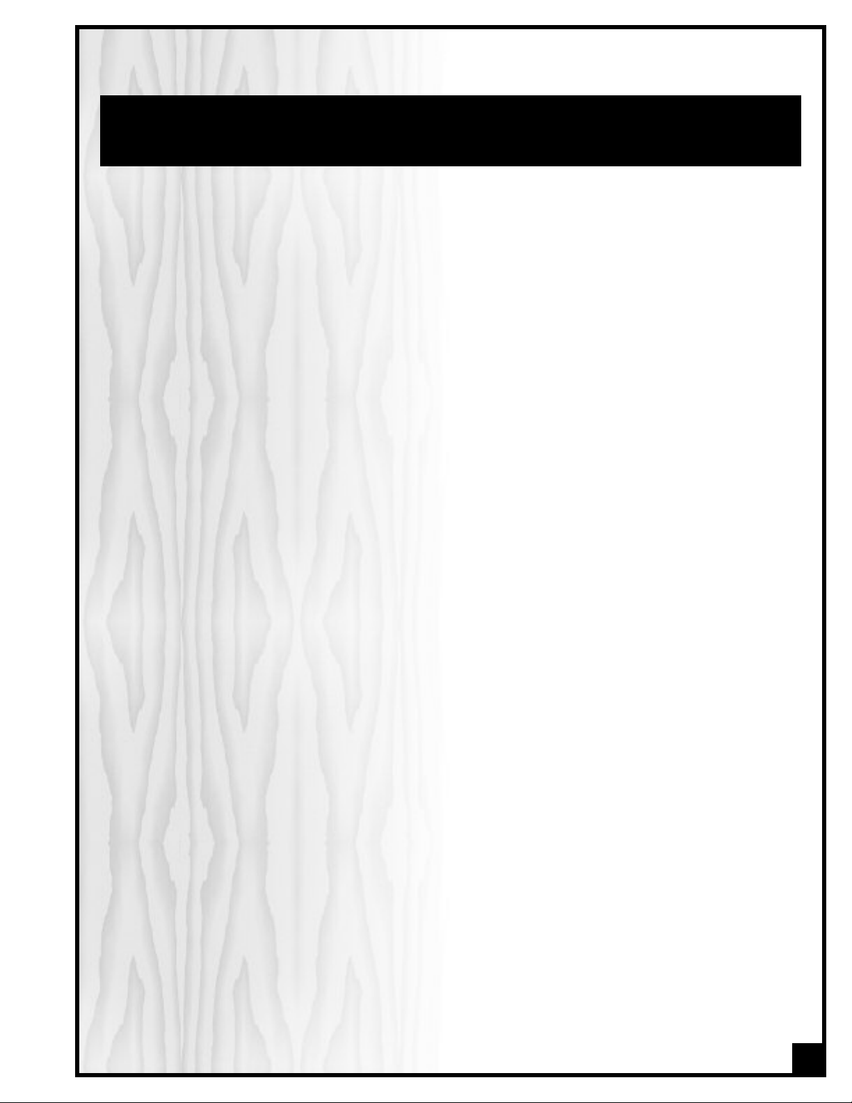
650RNK KIT INCLUDES:
New cast-iron saw chute assembly.
New arbor bracket assembly (with arbor)
with built-in riving knife mounting
block/receptacle.
New riving style splitter/blade guard
assembly.
Riving knife
New table insert
Retro-fit instructional DVD
New & improved saw manual for new
650R saw.
ITEM
#650RNK
REVISION 1 - March 29/09
ight General®MFG / General® Inter
yr
© Cop
national 03/2009
Page 2

GENERAL® MFG (CO) LTD.
835, Cherrier Street, Drummondville (Quebec) Canada J2B 5A8
Telephone (514) 326-1161 • Fax (514) 326-5555 • www.general.ca
THANK YOU for choosing this General
®
MFG model 650RNK Riving knife conversion / Retrofit kit. This Retrofit kit has been carefully tested and inspected before shipment
and if properly installed, will provide you with years of reliable service. To ensure optimum performance and trouble-free operation, and to get the most from your investment, please take
the time to read this manual before assembling, installing and operating the unit.
The manual’
s purpose is to familiarize you with the safe operation, basic function, and features
of this retrofit kit as well as the set-up, maintenance and identification of its parts and compo-
ormal w
. This man
nents
fer the user instruction in the craft of woodworking. If you are not sure about the safety of
of
orming a certain operation or procedure, do not proceed until you can confirm, from
perf
ual is not intended as a substitute f
or f
oodworking instruction, nor to
knowledgeable and qualified sources, that it is safe to do so.
Once you’ve read through these instructions, keep this manual handy for future reference.
Disclaimer: The information and specifications in this
manual pertain to the unit as it was supplied from the
actory at the time of printing. Because we are commit-
f
ted to making constant improvements, General
ves the right to make changes to
ble car
eser
e is tak
en a
t the f
y to ensure that
actor
tional r
na
Inter
components, parts or features of this unit as deemed
necessary,without prior notice and without obligation to
install any such changes on previously delivered units.
Reasona
the specifications and information in this manual corres-
ponds with that of the unit with which it was supplied.
However, special orders and “after factory” modifications may r
®
inapplicable to your machine. Further, as several gene-
tions of this model and se
ra
may be in circulation, if you own an earlier or later version of this unit, this manual may not depict your tool
exactly. If you have any doubts or questions contact
our r
y
of your unit for clarification.
ender some or all information in this manual
ersions of this manual
eral v
v
etailer or our suppor
t line with the model n
umber
Page 3
RULES FOR SAFE OPERATION
To help ensure safe operation, please take a moment to learn the machine’s applications and limitations, as well as poten-
ial hazards. General® MFG disclaims any real or implied warranty and holds itself harmless for any injury that may result
t
from improper use of its equipment.
o not operate the saw when tired, distracted, or
1.D
under the effects of drugs, alcohol or any medication that impairs reflexes or alertness.
he working area should be well lit, clean and free
2.T
of debris.
3. Keep children and visitors at a safe distance when
the saw is in operation; do not permit them to
operate the saw.
4. Childproof and tamper proof your shop and all
machiner
and switch keys, to prevent unauthorized or unsupervised use.
5. Stay alert! Give your work your undivided atten
tion. Even a momentary distraction can lead to serious injury.
6. Fine particulate dust is a carcinogen that can be
hazardous to health. Work in a well-ventilated area
and whenever possible use a dust collector and
wear eye, ear and respiratory protection devices.
7. Do not wear loose clothing, gloves, bracelets,necklaces or other jewelry while the saw is in operation.
Wear protective hair covering to contain long hair
and wear non-slip footwear.
8. Be sure that adjusting wrenches, tools, drinks and
other clutter are removed from the machine and/or
the feed table surface before operating.
9. Keep hands well away from the blade and all moving parts. Use a brush, not hands, to clear away
chips and dus
10. Be sure that the blade is securely installed and in
proper cutting direction before operation.
11. Be sure the blade has gained full operating speed
before beginning to cut.
w
12. Al
Dirty or dull blades are unsafe and can lead to
accidents.
13. If using a power feeder, stop the feeder before stopping the ta
y with locks, master electrical switches
t.
ly sharpened blade.
ays use a clean,
ble saw.
proper
se suitable support when cutting stock that does
15.U
not have a flat surface. Always hold stock firmly
against the fence when ripping, or against the miter
gauge when cross-cutting.
16. To minimize risk of injury in the event of workpiece
kickback, never stand directly in-line with the blade
or in the potential kickback path of the work piece.
17. Avoid working from awkward or off balance positions. Do not overreach while cutting; keep both
feet on floor. Never lean over or reach over the
blade and never pull the work piece over the blade
from behind. Use out feed support or have an assistant help when ripping long material.
18. Keep blade guards in place and in working order.
If a guard must be removed for maintenance or
cleaning, be sure it is properly reattached before
using the tool again.
19. Never leave the machine running with the power
on when not in operation.
20. Use of parts and accessories NOT recommended
by
GENERAL MFG
function or risk of injury.
21. Never stand on machinery. Serious injury could
result if the tool is tipped over or if the blade is unintentionally contacted.
22. Always disconnect tool from power before servicing
or changing accessories such as blades, or before
orming an
perf
ments, or if the machine will be left unattended.
e that switch is in "OFF" position bef
23. Mak
24. Make sure the tool is properly grounded. If equip-
25. Do not use this saw for other than its intended use. If
e sur
plugging in the power cord.
ped with a 3-prong plug it should be used with a
ee-pole receptacle. Never remove the third
thr
prong.
used for other purposes,
any real implied warranty and holds itself harmless
or any injury, which may result from that use.
f
may result in equipment mal-
y maintenance,
cleaning or adjust-
GENERAL MFG
ore
disclaims
14. Do not push or force stock into the blade. The saw
will perform better and more safely when working
at the rate for which it was designed.
3
Page 4

RIVING KNIFE CONVERSION / RETROFIT KIT
650RNK
BASIC FUNCTIONS
The parts and components supplied in this 650RNK riving knife retro-fit / conversion kit have been designed to fit on
General MFG 3HP* left tilt model 650** saw only.
a
*For 5 HP motors, modifications to the motor shaft will be required - contact our technical service or your local distributor for details
before attempting this conversion.
** If you have a model 350 right-tilt saw, you will require retro-fit kit model #350RNK. This kit cannot be fitted to a model 350 Righttilt saw!
HIS KIT HAS NOT BEEN DESIGNED NOR TESTED TO FIT ON ANY SAW MODEL OTHER THAN AS SPECIFIED IN THIS MANUAL. ANY
T
TTEMPTS TO FIT OR USE THESE PARTS AND COMPONENTS ON ANY SAW OTHER THAN THE MODEL INTENDED, MAY LEAD TO
A
SERIOUS PERSONAL INJURY, DAMAGE TO YOUR SAW AND/OR TO THE PARTS AND COMPONENTS OF THIS KIT.
A word a
Upon completion of your saw conversion using this kit, your saw will be equipped with the latest feature available
for North American table saws: A quick connect/ quick release riving knife style of splitter.
A riving knife is considered a newer design for North American saws which traditionally have been equipped with
various fixed height splitter assemblies which perform a similar function. The riving knife has proven effective and
has been in use on saws in Europe for many years and is becoming a required table saw safety accessory for new
saws throughout most of North America.
The riving knife sits behind the blade to help prevent a workpiece, as it is pushed through the cut,from closing back
and “pinching” the blade or from drifting away from the rip fence and catching the rear portion of the saw blade.
Such situations can lead to what is commonly referred to as a kickback, where by the shear force of the saws motor
and with the forward rotation of the blade,the workpiece is lifted and violently ejected towards the front of the saw.
A kickback can cause serious injury to the user or to anyone within its path.
A traditional splitter does not raise or lower with the blade – it stays at a fixed height at all times, meaning that when
the blade is lowered, the distance between the splitter and the back of the blade increases. The generally accepted theory is that more space between the splitter and the back of the blade does slightly increase the possibility
that the w
saw.
The riving knife however is designed into the blade height adjustment mechanism and not only will it tilt with the
blade but also raise or lower as the blade is raised or lowered, thus keeping it at the exact same distance, usually
some
considered to be a more effective means of helping to prevent kickback caused by the workpiece pinching or
catching on the back of blade.
bout riving knives:
kpiece could pinch or ca
or
e between 1/4”
her
w
tch on the bac
– 3/8” from the back of the blade at all times. Because of this, a riving knife is generally
k end of the blade and then be thrown towards the front of the
Like a traditional splitter/blade guard assembly, a riving knife can also be part of an assembly that includes a
blade guar
splitter/guard assembly, because unlike a traditional splitter/blade guard assembly it does still raise and lower with
the blade.
It is important to note however, that though generally considered more effective at preventing kickback from workpiece pinching or catching on the blade, because there is no blade guard, a true riving knife offers no protection
to the user against accidental contact with the blade. In such cases a stand alone or independently mounted
blade guar
d and anti-kickback pawls.
ed.
equir
er is r
v
d/co
This type of an assembly is commonly referred to as a “riving style”
4
Page 5
ARNING! TO REDUCE THE RISK OF SERIOUS INJURY FROM CONTACT WITH THE BLADE, THE RIVING KNIFE MUST ALWAYS BE
W
SED WITH A BLADE GUARD IN PLACE TO COVER THE BLADE. IF YOU DO NOT OWN AN INDEPENDENTLY ATTACHED BLADE
U
GUARD, THEN USE THE SUPPLIED RIVING STYLE SPLITTER/BLADE GUARD ASSEMBLY FOR ALL OPERATIONS THAT LEAVE THE
BLADE EXPOSED.
Before Starting:
To obtain a good understanding of what will be required, start by watching the DVD video which shows the major
steps and includes some helpful tips and tricks.
After watching the DVD video, read this entire manual and make sure you have all the tools and equipment
required to complete this conversion before starting.
The conversion of an older saw to the new style riving knife design involves heavy lifting, as well as partial disassembly and then re-assembly of some of the major internal components of your saw. Upon completion of re-assembly,
e-alignment of the saws table in relation to the blade is also required. If you are not equipped for or comfortable
r
with this type of mechanical work or if you have any doubt that the required lifting, disassembly, re-assembly or realignment steps are beyond your abilities or skill level:
Stop immediately and proceed no further. Return this kit
and all components in its original packaging to the place of purchase for refund, or contact your local
General/General International distributor to inquire if any on-staff technicians are available and to obtain a quote
to have this kit installed by a trained technician.
UNPACKING
Carefully unpack and remove the components from the box and check for damaged or missing items as per the
list of contents below.
NOTE: Please report any damaged or missing items to your General® International distributor immediately.
LIST OF CONTENTS QTY
A - CHUTE . . . . . . . . . . . . . . . . . . . . . . . . . . . . . . . . . . . . . .1
B - ARBOR BRACKET . . . . . . . . . . . . . . . . . . . . . . . . . . . . . .1
C - SPLITTER /BLADE GUARD ASSEMBLY . . . . . . . . . . . . . .1
D - 3/32" ALLEN KEY . . . . . . . . . . . . . . . . . . . . . . . . . . . . . .1
5/32"
ALLEN KEY . . . . . . . . . . . . . . . . . . . . . . . . . . . . . .1
E - ARBOR WRENCH . . . . . . . . . . . . . . . . . . . . . . . . . . . . .1
F - EUROPEAN STYLE RIVING KNIFE . . . . . . . . . . . . . . . . .1
G - T
ABLE INSERT . . . . . . . . . . . . . . . . . . . . . . . . . . . . . . . . .1
H - OPERATION MANUAL FOR 650R SAW . . . . . . . . . . . . .1
I - OPERA
TION MANUAL FOR 650RNK
. . . . . . . . . . . . . . .
J - DVD . . . . . . . . . . . . . . . . . . . . . . . . . . . . . . . . . . . . . . . .1
TOOLS REQUIRED TO COMPLETE THIS CONVERSION:
• Socket kit
y set
e
Allen k
•
• 2 large flat head screw
drivers
Rubber mallet
•
Hammer
•
• 3/16” punch or metal
marking awl
• Brass knock-out bar or
long hardwood dowel
General pur
•
machine gr
• Machinists square
Dial indica
•
alignment)
Another per
•
with lifting
pose
ease
or ta
tor/ (f
son for help
ble
1
A
D
C
F
H
B
E
G
I
J
5
Page 6
PREPARATION BEFORE STARTING
45
3
5
4
0
0
5
1
0
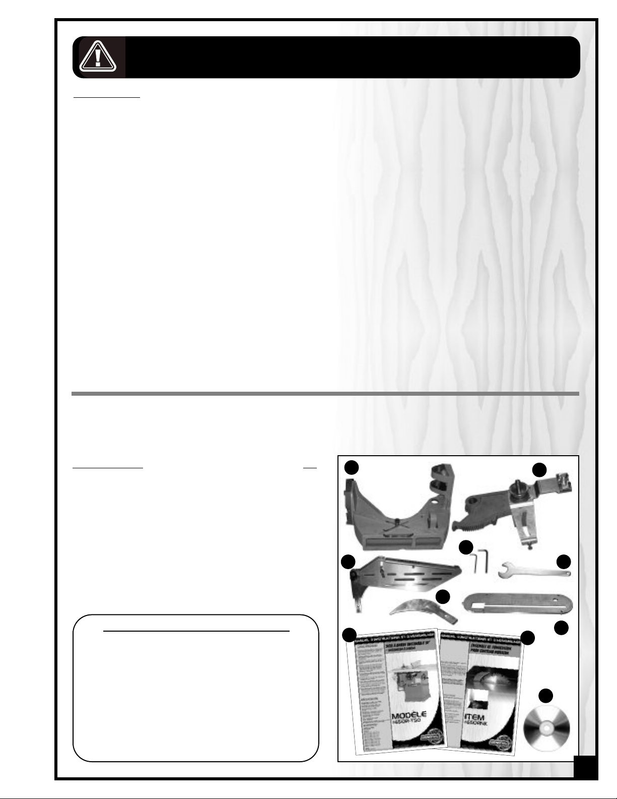
1. Turn off and disconnect the saw from the power source.
A
B
2. Set the blade to 90° and then remove the blade.
3. Remove and set aside the fence and rails, A.
4. Remove the switch.
5. Remove motor cover door, B.
DISASSEMBLY
Note: The parts reference numbers in brackets in the instructions written in this manual refer to the reference number of the
item as shown in the parts diagram in the original saw manual (a copy of this diagram is included on page #18 of this
manual) during disassembly, and to the new 650R saw manual (supplied with this kit) for re-assembly.
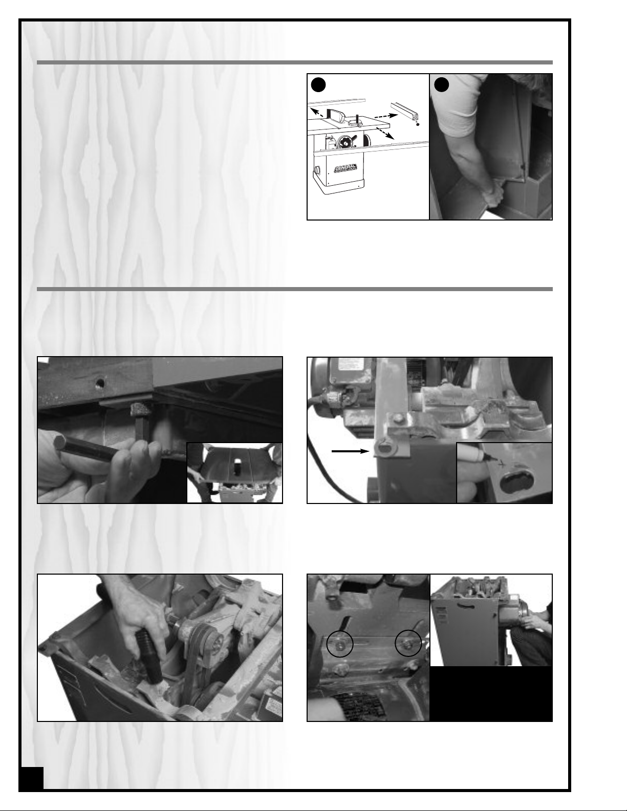
ten the 4 cap screws under the table and with
as
1. Unf
the help of an assistant carefully remove and set the
table aside.
2. Vacuum out any sawdust inside the saw cabinet.
6
Note: If the table has been factory shimmed, take note of
shim placement and be sure to re-install shims to the same
location(s) during re-assembly later.
2 above & 2 below motor
Hint – to avoid dropping or
ing the motor, brace the
damag
motor against y
shown, while loosening and
emoving it from the base plate.
r
our knee as
3. Unfasten the 4 bolts holding the motor mounting
bracket to the motor base plate (#59) and carefully
remove and set aside the motor and the drive belts.
Page 7
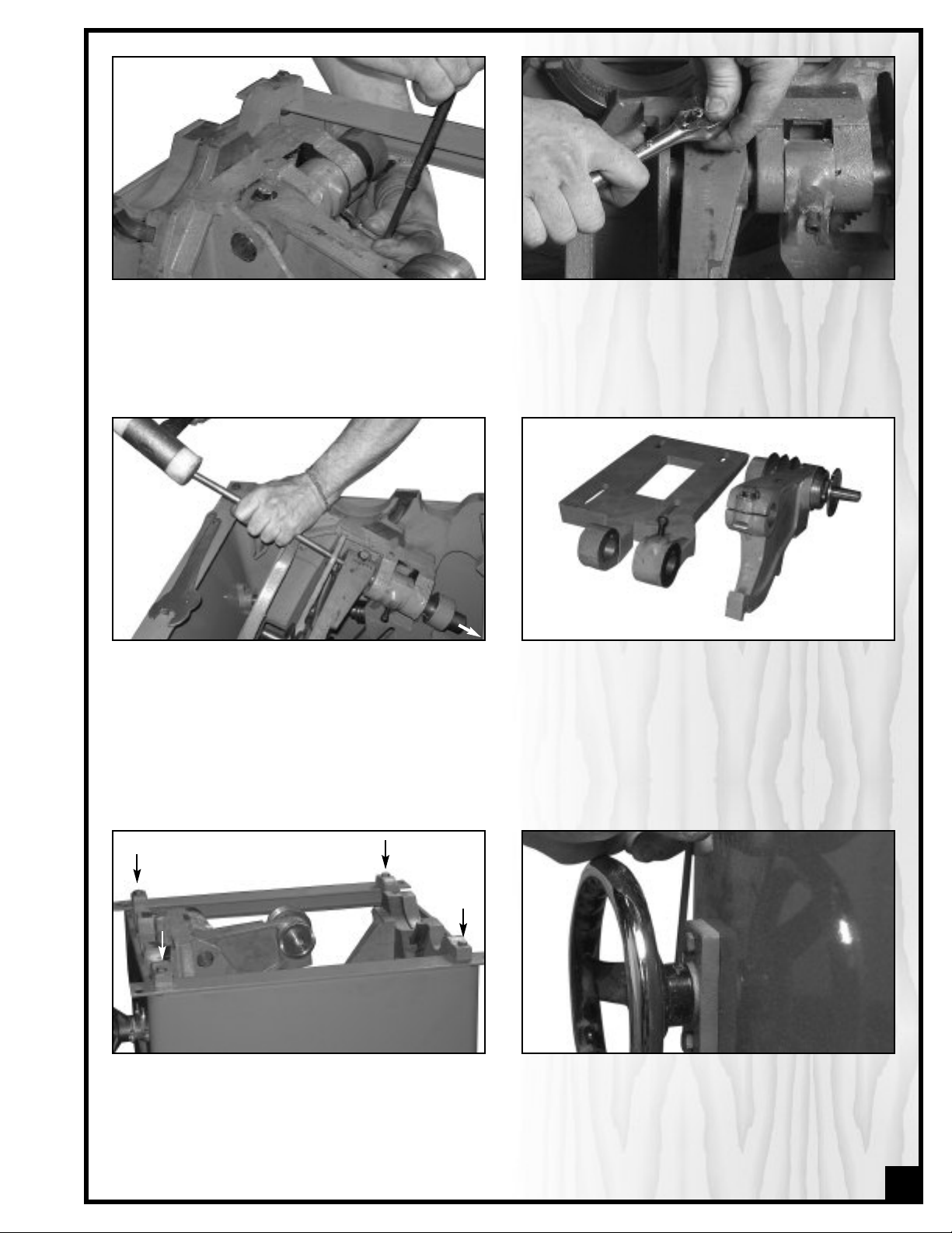
4. Loosen, but do not remove, the cap screw (#36) on
the motor base (#59).
5. Loosen but do not remove the bolt (#2) on the top of
the arbor bracket (#37).
6. Tilt the arbor mechanism to 45° and using a brass
bar or hardwood dowel and mallet, remove and set
aside the pin (#34) through the arbor bracket,chute
and motor base plate.
9. Unfasten and remove the 4 bolts that secure the
trunnions to the cabinet, along with their corresponding washers and nuts.
7. Carefully remove and set aside the motor base
plate (#59) and the arbor bracket (#37).
8. Tilt the arbor mechanism back to 90°.
10. Loosen the set screw (#19) that holds the blade
tilt hand wheel (#58) onto its shaft (#13).
7
Page 8

11. Unscrew and remove the lock knob (#20) and then
remove the hand wheel.
12. Remove and set aside the key in the keyway on the
shaft.
13. Remove the 2 bolts (#7) that hold the blade tilt
flange (#5) to the cabinet, and remove the flange.
#58
#20
15. Remove the front hand wheel (#58) by removing
the lock knob #20) and loosening the set screw
(#19).
#19
14. Temporarily re-install the lock-knob (#20) threading
it slowly back onto the shaft (#13). This will push out
the 2 guide pins (#14) in the shaft. Remove and set
the pins aside.
Note: when re-installing the guide pins later, make sure to
insert them in the shaft with the pointed ends facing
inwards.
16. Remove and set aside the key in the keyway on the
shaft.
8
Page 9

17. Unscrew and remove the angle pointer (#23 & 24)
from the front of the saw.
19. With the rear trunnion removed carefully remove
and set aside the chute (#30), hanging from the
front trunnion (#1).
Carefully pry one end of the rear trunnion (#53)
18.
down into the cabinet and then slide the rear trunnion up and away from the saw through the top
opening. If needed, use large flat head screwdrivers for leverage when prying.
TRANSFERRING PARTS
Before disposing of the old chute you must transfer some of the components from the old chute onto the new one.
ollowing steps explain how to remove and then re-install the blade height adjustment worm gear (#32) and
The f
shaft (#31), as well as the front tilt trunnion (#26).
#9
1. Set the chute on its side on a ta
and rotate the worm gear (#32) until the spring pin
(#9) that holds the collar (#10) onto the shaft is
ds.
acing upw
f
ar
ble or w
or
kbench,
ith a metal punch,
2. W
both the collar and the shaft that line up with the
spring pin. This will facilitate re-aligning the collar
and shaft to r
during re-assembly later.
e-ins
mak
tall the spr
ing pin in its hole
ence mar
efer
e a r
k on
9
Page 10

3. Using a punch and a hammer, gently tap on one
end of the spring pin and remove it from the
collar/shaft.
4. Slip the collar off of the shaft and set it aside along
with any spacers (fibre washers) on the shaft.
Note: when re-installing these parts on the new chute, your
retro-fit kit also includes extra spacers that can be used (if
needed) to help eliminate any play on the shaft between
the collar and the worm gear.
5. Unscrew and remove the 4 bolts (#22) that hold the
front tilt trunnion to the chute.
8. Apply a generous dab of any common machine
et on the
ease to the opening in the shaft brac
gr
k
new chute as well as the worm gear and shaft.
6. Gently tap or pry as needed to remove the front tilt
trunnion from the chute. The worm and shaft will
follow.
7. Set aside the old chute and bring the new chute
onto your work table to begin transferring the parts
that were just removed.
Note: The alignment pins protruding from the tilt trunnion will
help facilitate lining up the bolt
holes in the chute.
9. Using a rubber mallet carefully fit the front tilt trun-
m gear
nion onto the ne
w chute,
sliding the w
or
shaft into the hole in the bracket on the chute.
10
Page 11

10. Secure the tilt trunnion to the chute using the 4 bolts.
11. Slip the collar and spacer onto the end of the
worm gear shaft and line up the alignment marks
(made with the punch during disassembly) on the
shaft and collar.
12. Tap the spring pin all the way into the hole in the
collar to secure the collar to the shaft. Tug on the
shaft to verify for play between the collar and
the bracket.
If needed, remove the spring pin and collar again and
add extra spacers to eliminate any play.
RE-ASSEMBLING AND ALIGNING THE SAW
unnion (s
wn the trac
ipe do
1. W
installed on the saw) and the rear trunnion removed earlier) to clean off old grease and dust
and then a
grease to both.
ks in both the fr
pply a gener
ont tr
ous amount of fr
till
esh
e and set aside the thr
2. Remo
v
lower part of the new chute and set it aside.
eaded knob on the
11
Page 12

3. Install the new chute back in the saw, hanging it in
the cabinet from the front trunnion.
4. Slip the rear trunnion back into place through the
top opening, mating it with the back end of the
new chute and sitting it on the cabinet.
5. Loosely install the 4 trunnion bolts with their washers
and nuts into the holes through the trunnions and
the corners of the cabinet.
7. To keep the cabinet more or less square, gradually begin tightening the tr
checking that the diagonal measurements match
from corner to corner to the center of the bolt
heads. Gently tap on the cabinet corners with a
rubber mallet as needed, while tightening the bolts
ing the cabinet into square.
to br
Note: extremely high precision is not required; diagonal
corner to corner measurements that are within 1 /16” of
each other are more than adequate.
unnion bolts while
6. Slip a large flat head screwdriver between the front
and rear trunnions and the cabinet to remove any
play between them.
8. Remove the screwdrivers from the cabinet once
unnions have been secur
the tr
9. Re-install the alignment pins in the shaft on the
table tilt hand wheel with the points facing inward.
ed to the ca
binet.
12
Page 13

10. Re-install the blade tilt flange on the cabinet and
secure it loosely with the 2 bolts.
11. Before completely tightening the flange to the
cabinet, install the lock knob (temporarily) to push
on the guide pins and help align the flange and
then tighten the 2 bolts to tighten the flange to the
cabinet.
12. Remove the lock knob and re-install the key in the
keyway on the shaft.
pointer will be properly aligned later).
13. Install the blade tilt hand wheel on the shaft, reinstall the lock knob and tighten the set screw to
secure the hand wheel on the shaft.
15. Re-install the key in the keyway on the shaft 14. Re-install the pointer and the front hand wheel (the
13
Page 14

the set screw and then install the lock knob.
17. Turn the tilt hand wheel to set the chute to 45°.16. Secure the hand wheel to the shaft by tightening
18. Fit the pin into the first part of the motor base plate
(lining up the keys with the keyway in the bracket,
and keyway in the pin with the cap screw on the
motor base plate.
Flush her
20. Fit the new arbor bracket in place making sure to
position the slotted ar
assembly (#57) pointing more or less downwards.
Tap on the pin until the end of the pin is through the
holes in the arbor bracket and sits flush with the
opening in the hole in the chute.
m of mounting brack
e
et
19. Fit the base plate onto the chute and gently tap
the pin through the holes in the bracket of both the
base plate and the chute, only enough to hold the
base plate onto the chute.
21. Tighten the cap screw to secure the motor base
te to the pin.
pla
14
Page 15

22. Turn the tilt hand wheel and set the carriage
assembly to 90°.
23. Align the threaded hole in the bottom of the chute
with the curved slot in the arm of the mounting
bracket and re-install the threaded knob removed
and set aside earlier (step #12).
24. Verify the gaps between the head of the knob and
the arm, and also the arm and the chute are more
of less equal. If needed lightly pry the arbor bracket left or right on the pin to center the arm
een the knob and the chute.
betw
Loosen
set screw
to remove
Tighten
set screw
26. Before re-installing the motor on the base plate,
remove and reverse the motor pulley on the shaft.
This will facilitate pulley alignment with this new
.
ter
tion la
igura
conf
25. Tighten the hex head bolt on the arbor bracket to
secure everything in place on the pin.
27. Install the drive belts on the arbor pulleys and slip
the motor pulleys onto the lower portion of the belts
to essentially hang the motor from the belts.
15
Page 16

28. Line the motor bracket holes up with the holes in
the motor base plate and loosely fasten the motor
to the base plate using all 4 bolts.
29. Use a piece of scrap wood for leverage and pry
down on the inside portion of the motor to help
hold the motor shaft as close to horizontal as possible and to tension the belts. Have an assistant
hold a straight edge to the pulleys to check and
adjust pulley alignment while tightening the bolts
to secure the motor to the base plate.
30. With the help of an assistant put the table back on
the saw and secure it loosely with the cap screws –
make sure to re-install any factory installed table
shims to their correct locations.
32. Slowly tilt the blade to 45° and then back to 90°
while looking for obstructions or unwanted contact
een the blade and the ta
betw
between the newly installed carriage under the
table and the underside or opening in the table.
t the ta
Adjus
ble positioning slightly if needed.
ble insert and also
31. Install a blade on the saw and raise it to maximum
height and install the new table insert in the table
opening. Depending on your table casting it may
be necessary to file down a portion of the inserts
alignment pin.
Note: Depending on your table casting it may be necessary to partially grind down one or several of the protrusions in the table opening to obtain full clearance.
16
Page 17

33. Set the blade to 90° and using an accurate dial
indicator in either of the miter slots. Check and set
the miter slot parallel to the blade to within 5 thousandths of an inch, by gently tapping on the
appropriate edge of the table with a rubber mallet. Gradually tighten all 4 cap screws while regularly double checking alignment until the table is
secured in place.
35. Adjust the saws 90° and 45° bevel stops and the angle indicator pointer as per the instructions supplied on
page 22 of the new manual supplied in your kit for the 650R saw.
36. Install and adjust the riving knife as per the instructions supplied on page #11-13 of the new manual supplied
in your kit for the 650R saw.
37. With the blade at maximum height and the riving knife installed, manually rotate the blade at least one full turn
at both 90° and again at 45°. Check for obstructions and to confirm that you have full blade and saw carriage
clearance. If needed, return to previous steps and re-adjust or grind down any obstructions before turning on
the saw.
34. Raise the blade to its maximum and measure it’s
height above the table. Maximum blade height
(for a 10” diameter blade) is 3 1/8”. If needed,
adjust the blade height limiter bolt on the bottom
of the slotted arm, to obtain a 3 1/8” blade height.
O AVOID DAMAGING THE BLADE OR ANY OF THE
T
INTERNAL COMPONENTS OF THE SAW, DO NOT
ADJUST TO GO BEYOND A 3 1/8” BLADE HEIGHT.
38. Re-install the fence rails, switch and motor cover door. Before plugging in and using the saw, follow the instruc-
tions in your new 650R saw manual (supplied with this kit) to:
A) Align the r
B) Check and adjust the 90° and 45° bevel stops.
C) Re-align the angle pointer.
D) Install, align, and use your new riving knife.
Congratulations! Y
Thank y
ou for choosing General MFG – w
ip fence parallel to the blade.
ersion should now be completed.
our saw con
v
e wish you safe and ha
ppy woodworking!
17
Page 18

18
17
20
58
19
7
5
13
15
10
1
23
24
25
31
14
26
28
29
6
27
8
32
9
11
49
48
62
5
6
61
42
39
60
30
37
50
35
34
55
54
3
2
43
19
38
40
53
2
3
4
22
52
6
7
21
12
14
8
9
11
58
17
18
20
19
8
9
11
9
10
11
8
15
4
3
2
22
21
39
19
59
5
1
57
6
3
36
64
65
650 SAW MECHANISM
(Without riving knife kit)
18
Page 19

11
33
44
55
1717
3030
2121
2525
2828
2727
2424
5353
5
959
5757
2929
5858
35
4444
99
11
44
4242
5151
4141
4343
99
5252
4646
4343
4545
4
747
4848
4949
5
050
5454
3939
3737
4040
3838
3636
2
727
2525
2626
1212
1313
1111
1515
1616
2020
2222
2323
2121
2424
1717
1414
1919
1818
11
22
44
55
3232
3131
99
1010
66
88
77
2828
2525
2727
99
2424
1010
88
77
66
2727
2525
2424
3434
3333
1111
1313
3131
5555
5656
650R SAW MECHANISM
(With riving knife kit)
19
Page 20

650R SAW MECHANISM
P
ARTS LIST
650R
EF. N0. PART N0. DESCRIPTION SPECIFICATION QTY
R
1 P-6 HEX. HEAD BOLT 3/8-16 UNC X 1 1/2 5
2 654-1 FRONT TRUNNION 1
3 654-4 REAR TRUNNION 1
4 P-15 LOCK WASHER 3/8" 5
5 P-17 NUT 3/8-16 UNC 4
6 354-12SA LOCK KNOB ASSEMBLED 2
7
8 P-332 HANDLE 354-14 2
9 P-7 ALLEN SET SCREW 5/16-18 UNC X 5/16" 4
10 354-9SA HAND WHEEL ASSEMBLY 2
(With riving knife kit)
11 354-23 KEY 2
12 354-7 ELEVATING SHAFT 1
13 354-13 GUIDE PIN 4
14 354-8 MAIN BEARING 1
15 P-100 HEX. HEAD BOLT 5/16"-18 UNC X 3/4" 2
16 P-51 LOCK NUT 5/16-18 UNC 2
17 P-35 HEX. HEAD BOLT 3/8"-16 UNC X 1" 6
18 P-116 TAPPING-SCREW 8-32 UNC X 3/8 1
19 354-17 POINTER 1
20 654-2 FRONT TILT TRUNNION 1
21 P-111 SPRING PIN 1/4 X 3/4 4
22 P-305 HEX. HEAD BOLT 5/16"-18 UNC X 1 1/2" 2
23 P-135 LOCK WASHER 5/16" 4
24 P-70 COPPER BEARING SS-2428-12 4
25 P-126 SPRING PIN 3/16" X 1 1/4" 4
26 554-23 LEFT WORM 1
27 P-77 FIBER WASHER 3/4 X 1 1/4 X 1/32 4
28 354-6 COLLAR 2
29 654 CHUTE 1
30 654-3 REAR TILT TRUNNION 1
31 P-99 HEX. HEAD BOLT 5/16" -18 UNC X 1" 8
32 354-11 FLANGE 1
33 354-10 TILT SHAFT 1
34 354-5 RIGHT GEAR 1
35 653 ARBOR BRACKET 1
36 354-22 KEY 1
37 P-304 HEXAGONAL SOCKET HEAD CAP SCREW 5/16-18 UNC X 1" 1
38 354-21 KEY 1
39
40 354-20
41 P-106 HEXAGONAL LOCK NUT 5/8-18 UNC 1
42 P-108 SNAP RING N-1308-168 2
43
44 353-3 ARBOR PULLEY 1
45
46 353-5B LARGE SPACER 1
47 653-1ASS ARBOR WITH FLANGE AND NUT 1
48 P-1029 CARBIDE COMBINATION BLADE 9.840" - 50 TEETH 1
49 353-2
50 653-3 RIGHT-HAND THREAD 5/8-10 ACME 29 DEGREES 1
51 P-1217 BELT A-24 26" LONG 2
52 353-8
53 353-7 ARBOR WRENCH 1
54
55 55 P-1084 FLAT WASHER 5/16" 4
56 56 P-182 NUT 5/16-18 UNC 4
57 657 MOUNTING BRACKET ASSEMBLY (650) 1
58
59 59 P-308 OUTER HOLD-DOWN RING SÉRIE R3100-200 1
354-15 HANDLE PIN 2
654-19A MOTOR BASE 1
PIN 1
P-279 BEARING
P-4 W
354-24
58 357-33
OODRUFF KEY #9-3/16" X 3/4" 1
VED
CUR
MOTOR PULLEY(STANDARD) 7/8" 1
TOR SPACER 2
MO
GUIDE PIN
ASHER 1
W
6203-2RS 2
1
20
Page 21

3
2
1
SPLITTER / BLADE GUARD ASSEMBLY – RIVING KNIFE
18
17
16
15
1
4
13
12
4
9
8
6
5
7
11
10
28
26
2
7
24
25
22
2
3
2
0
21
1
9
2
9
PARTS LIST
REF. N0. PART N0. DESCRIPTION SPECIFICATION QTY
1 657 MOUNTING BRACKET ASSEMBLY (650) 1
2 357-21 RIVING KNIFE 1
3 350-7R SPLITTER/BLADE GUARD ASSEMBLY 1
4 357-24 SPLITTER 1
5 P-221 ROUND HOOK 4
6 357-29 WASHER 4
7 357-25 GUARD ARM 2
8 357-28 MIDDLE WASHER 1
9
357-1S
GUARD ASSEMBLY 1
10 357-26 ANTI-KICKBACK PAWL 2
11 P-208 GROOVED PIN 3/16 "X 3/4" 1
12
P-445 SPUR SPRING
357-12A
1
13 357-30 GUARD PIN 1
14 P-166 NYLON WASHER .062 X 5/16I.D.X 7/8 O.D. 2
15
16
ARD PIV
357-31
GU
357-32 ANTI-KICKB
OT 1
WL PIN
A
CK P
A
1
17 P-203 FLAT WASHER #8,.062 X 3/16 I.D. X 1/2 O.D. 1
18
19
P-116
ROUND HEAD MA
657-20 ROCKER
ARM (650) 1
CHINE SCREW
, SQUARE GRIP #2,#8-32 UNF X 3/8 1
20 357-22 ADJUSTMENT SPACER 1
SET SCREW
AP SCREW
C
HOLD-DO
LOCK
KNOB
OUTER HOLD-DO
WN BLOCK 1
ASHER
W
WN RING
P-152
357-23
P-496
21
22 P-312
23 P-140 COMPRESSION SPRING 1
24
25
26 P-395 CAP SCREW 10-32 X 3/4 4
27
28
29 P-717 GUIDE PIN 1
P-449
P-308
0-32 X .375
10-24 X 3/4 1
3/16
SÉRIE R3100-200
14
4
1
1
SPLITTER / BLADE GUARD ASSEMBLY – RIVING KNIFE
21
Page 22

RIVING KNIFE CONVERSION/RETROFIT KIT
835, Cherrier Street, Drummondville (Quebec) Canada J2B 5A8
Tel.: (514) 326-1161
F
ax: (514) 326-5565 -
P
arts & Service /
orderdesk@general.ca
www
F
ax: (514) 326-5555 -
.general.ca
Or
der Desk
IMPORTANT
When ordering replacement parts, always give the model number, serial number of the machine and
part number. Also a brief description of each item and quantity desired.
 Loading...