

Page 1
SETUP & OPERATION MANUAL
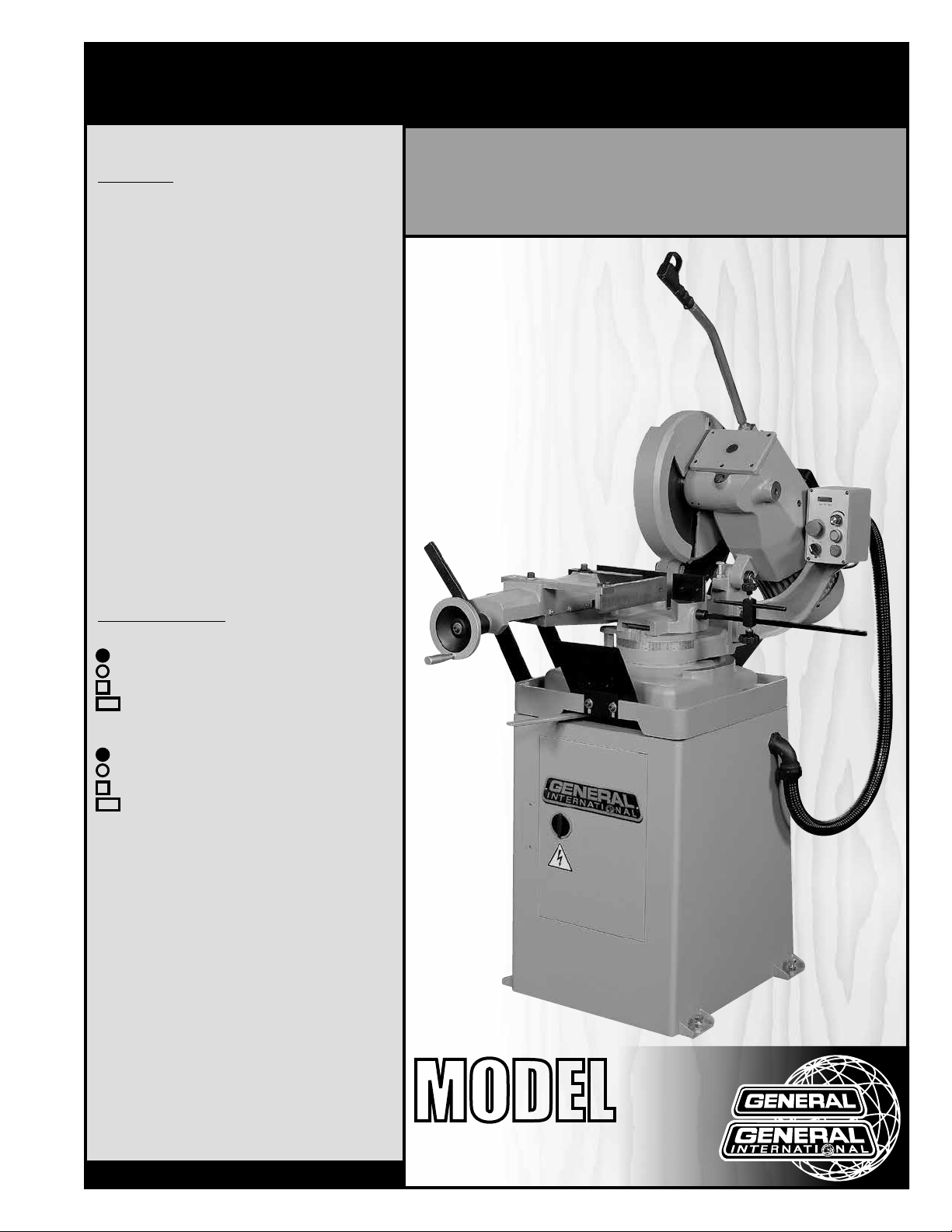
FEATURES
Powerful 3 HP motor provides plenty of power to
suit a wide variety of cutting applications.
Variable blade speed - ideal for cutting ferrous
materials.
Mitering capabilities - stops at 90°, 45° left and
45° right.
Heavy-duty spindle and worm gear box.
Quick-clamp vise for easy work piece loading.
Control handle with safety trigger switch.
Coolant pump system with high volume tank.
Specially designed water channel for better
cooling effect.
Shock-proof control panel.
Overload protected inverter.
Digital spindle speed display.
SPECIFICATIONS
• Cutting capacity at 90º
3 3/8” (85 mm)
4 3/4” (120 mm) 3” (75 mm)
4” x 4” (102 x 102 mm)
6 1/8” x 3 1/2” (155 x 90 mm)
14” COLD CUT SAW
-
ELECTRONIC VARIABLE SPEED
• Cutting capacity at 45°
3” (75 mm)
3 3/4” (95 mm)
3 1/8” x 3 1/8” (80 x 80 mm)
3 1/8” x 2 3/4” (80 x 70 mm)
• Blade
14” x 1 1/4” (350 x 32 mm) - optional
• Spindle speed
24 to120 rpm
• Maximum vise opening
6 11/16” (170 mm)
• Coolant pump
1/8 HP
• Coolant tank
5 liters
• Overall dimensions
47 1/4” x 40 1/8” x 76 3/4”
(1200 x 1020 x 1950 mm)
• Stand dimensions
23 5/8” x 22 13/16” x 28 3/8”
(600 x 580 x 720 mm)
• Motor
3 HP, 220 V, 3 Ph, 9.6 A
• Weight
550 lbs (250 kg)
Version #2_Revision #2 - October 2015
© Copyright General International
MODEL
#
60-350
Page 2

GENERAL® INTERNATIONAL
8360 Champ-d’Eau, Montreal (Quebec) Canada H1P 1Y3
Telephone (514) 326-1161 • Fax (514) 326-5555 • www.general.ca
THANK YOU
for choosing this General® International model 60-350 14”
variable speed cold cut saw. This cold cut saw has been carefully tested and inspected
before shipment and if properly used and maintained, will provide you with years of reliable
service. For your safety, as well as to ensure optimum performance and trouble-free operation,
and to get the most from your investment, please take the time to read this manual before
assembling, installing and operating the unit.
The manual’s purpose is to familiarize you with the safe operation, basic function, and features
of this cold cut saw as well as the set-up, maintenance and identification of its parts and
components. This manual is not intended as a substitute for formal metalworking instruction,
nor to offer the user instruction in the craft of metalworking. If you are not sure about the safety
of performing a certain operation or procedure, do not proceed until you can confirm, from
knowledgeable and qualified sources, that it is safe to do so.
Once you’ve read through these instructions, keep this manual handy for future reference.
DISCLAIMER: The information and specifications
in this manual pertain to the unit as it was supplied
from the factory at the time of printing. Because we
are committed to making constant improvements,
General® International reserves the right to make
changes to components, parts or features of this
unit as deemed necessary, without prior notice and
without obligation to install any such changes on
previously delivered units. Reasonable care is taken
at the factory to ensure that the specifications and
information in this manual corresponds with that of the
unit with which it was supplied. However, special orders
and ”after factory” modifications may render some
or all information in this manual inapplicable to your
machine. Further, as several generations of this model
of cold cut saw and several versions of this manual may
be in circulation, if you own an earlier or later version of
this unit, this manual may not depict your unit exactly. If
you have any doubts or questions contact your retailer
or our support line with the model and serial number of
your unit for clarification.
Page 3

GENERAL® INTERNATIONAL WARRANTY
All component parts of General® International and Excalibur by General International® products
are carefully inspected during all stages of production and each unit is thoroughly inspected upon
completion of assembly.
Limited Lifetime Warranty
Because of our commitment to quality and customer satisfaction, General® International agrees to
repair or replace any part or component which upon examination, proves to be defective in either
workmanship or material to the original purchaser for the life of the tool. However, the Limited Lifetime
Warranty does not cover any product used for professional or commercial production purposes nor
for industrial or educational applications. Such cases are covered by our Standard 2-year Limited
Warranty only. The Limited Lifetime Warranty is also subject to the ”Conditions and Exceptions” as listed
below.
Standard 2-Year Limited Warranty
All products not covered by our lifetime warranty including products used in commercial, industrial
and educational applications are warranted for a period of 2 years (24 months) from the date of
purchase. General® International agrees to repair or replace any part or component which upon
examination, proves to be defective in either workmanship or material to the original purchaser during
this 2-year warranty period, subject to the ”conditions and exceptions” as listed below.
To file a Claim
To file a claim under our Standard 2-year Limited Warranty or under our Limited Lifetime Warranty,
all defective parts, components or machinery must be returned freight or postage prepaid to
General® International, or to a nearby distributor, repair center or other location designated by
General® International. For further details call our service department at 1-888-949-1161 or your local
distributor for assistance when filing your claim.
Along with the return of the product being claimed for warranty, a copy of the original proof of
purchase and a ”letter of claim” must be included (a warranty claim form can also be used and can
be obtained, upon request, from General® International or an authorized distributor) clearly stating the
model and serial number of the unit (if applicable) and including an explanation of the complaint or
presumed defect in material or workmanship.
CONDITIONS AND EXCEPTIONS:
This coverage is extended to the original purchaser only. Prior warranty registration is not required but
documented proof of purchase i.e. a copy of original sales invoice or receipt showing the date and
location of the purchase as well as the purchase price paid, must be provided at the time of claim.
Warranty does not include failures, breakage or defects deemed after inspection by
General® International to have been directly or indirectly caused by or resulting from; improper use,
or lack of or improper maintenance, misuse or abuse, negligence, accidents, damage in handling or
transport, or normal wear and tear of any generally considered consumable parts or components.
Repairs made without the written consent of General® International will void all warranty.
Page 4

TABLE OF CONTENTS
Rules for safe operation ..................................................................................................... 5
Electrical requirements ...................................................................................................... 6
Identification of main parts and components .................................................................. 7
Unpacking .......................................................................................................................... 8
Basic functions ................................................................................................................... 8
Placement within the shop ................................................................................................ 9
Assembly instructions ................................................................................................... 9-14
Installing the downfeed handle ........................................................................................................................ 9
Installing a blade .............................................................................................................................................. 10
Installing the support roller .............................................................................................................................. 12
Installing the work stop .................................................................................................................................... 13
Installing the vise handle ................................................................................................................................. 14
Basic adjustments and controls ................................................................................. 14-17
Connecting to a power source .......................................................................................................................14
Magnetic switch ................................................................................................................................................ 14
Blade speed adjustment ................................................................................................................................. 15
Electronic system protector ............................................................................................................................. 15
Adjusting the cut angle .................................................................................................................................... 16
Adjusting the base swivel lock lever ...............................................................................................................16
Adjusting and using the vise ........................................................................................................................... 16
Adjusting the machine head stops ................................................................................................................ 17
Immobilizing the machine .............................................................................................................................. 17
Operating Instructions ..................................................................................................... 18
Checklist before starting .................................................................................................................................. 18
Operations step-by-step ................................................................................................................................... 18
Maintenance .................................................................................................................... 19
Cleaning ............................................................................................................................................................ 19
Changing the gear box oil .............................................................................................................................. 19
Fuse replacement ............................................................................................................................................. 20
Parts list & diagrams ................................................................................................... 21-26
Contact information ........................................................................................................ 28
Page 5

RULES FOR SAFE OPERATION
To help ensure safe operation, please take a moment to learn the machine’s applications and limitations,
as well as potential hazards. General
harmless for any injury that may result from the improper use of its equipment.
1. Do not operate the saw when tired, distracted, or un der the effects of drugs, alcohol or any medication
that impairs reflexes or alertness.
2. The work area should be well lit, clean and free
of debris.
3. Keep children and visitors at a safe distance when
the saw is in operation; do not permit them to ope rate the saw.
4. Childproof and tamper proof your shop and all ma chinery with locks, master electrical switches and
switch keys, to prevent unauthorized or unsupervised
use.
5. STAY ALERT! Give your work your undivided attention.
Even a momentary distraction can lead to serious
injury.
6. Fine particulate dust is a carcinogen that can be
hazardous to health. Work in a well-ventilated area
and whenever possible use a dust collector and
wear eye, ear and respiratory protection devices.
®
International disclaims any real or implied warranty and hold itself
13. Do not push or force stock into the blade. The saw
will perform better and more safely when working at
the rate for which it was designed.
14. To minimize risk of injury in the event of workpiece
kickback, never stand directly in-line with the blade
or in the potential kickback path of the work piece.
15. Avoid working from awkward or off balance posi tions. Do not overreach while cutting; keep both feet
on floor. Use out feed support or have an assistant
help when cutting long material.
16. Keep blade guards in place and in working or der. If a guard must be removed for maintenance or
cleaning, be sure it is properly re-attached before
using the tool again.
17. Never leave the machine running with the power on
when not in operation.
18. Use of parts and accessories NOT recommended
by General
malfunction or risk of injury.
®
International may result in equipment
7. Do not wear loose clothing, gloves, bracelets, neck laces or other jewelry while the saw is in operation.
Wear protective hair covering to contain long hair
and wear non-slip footwear.
8. Be sure that adjusting wren ches, tools, drinks and
other clutter are removed from the machine and/or
the table surface before operating.
9. Keep hands well away from the blade and all
moving parts. Use a brush, not hands, to clear away
chips and dust.
10. Be sure that the blade is securely installed and in-
proper cutting direction before operation.
11. Be sure the blade has gained full operating speed
before beginning to cut.
12. Always use a clean, properly sharpened blade. Dir ty or dull blades are unsafe and can lead to
accidents.
19. Never stand on machinery. Serious injury could
result if the tool is tipped over or if the blade is unin tentionally contacted.
20. Always disconnect tool from power before servicing
or changing accessories such as blades, or before
performing any maintenance, cleaning or adjust ments, or if the machine will be left unattended.
21. Make sure that switch is in ”OFF” position before plug ging in the power cord.
22. Make sure the tool is properly grounded. If equip ped with a 3-prong plug it should be used with a
three-pole receptacle. Never remove the third prong.
23. Do not use this saw for any purpose other than its
intended use. If used for other purposes,
General® International disclaims any real or im plied warranty and holds itself harmless for any in jury, which may result from that use.
5
Page 6
ELECTRICAL REQUIREMENTS
BEFORE CONNECTING THE MACHINE TO THE POWER SOURCE, VERIFY THAT THE VOLTAGE OF YOUR POWER
SUPPLY CORRESPONDS WITH THE VOLTAGE SPECIFIED ON THE MOTOR I.D. NAMEPLATE. A POWER SOURCE
WITH GREATER VOLTAGE THAN NEEDED CAN RESULT IN SERIOUS INJURY TO THE USER AS WELL AS DAMAGE
TO THE MACHINE. IF IN DOUBT, CONTACT A QUALIFIED ELECTRICIAN BEFORE CONNECTING TO THE POWER
SOURCE.
THIS TOOL IS FOR INDOOR USE ONLY. DO NOT EXPOSE TO RAIN OR USE IN WET OR DAMP LOCATIONS.
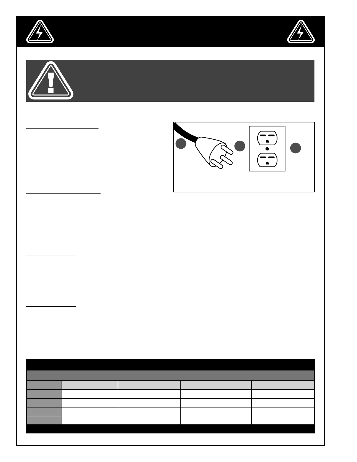
ELECTRICAL CONNECTIONS
Both a manual circuit breaker (or similar device) as well
as an electrical plug (similar to the one shown) are recommended and SHOULD BE INSTALLED BY A QUALIFIED
ELECTRICIAN.
Use locally approved wire A that includes a separate
grounding wire and a 3 prong grounding type plug B
with a matching receptacle C.
GROUNDING INSTRUCTIONS
In the event of an electrical malfunction or short circuit, grounding reduces the risk of electric shock to the operator. The motor of the ”M1” model of this machine is wired for 220 V single phase operation. As with many stationary
industrial type machines, because each installation situation is unique, this machine is supplied without a power
cord or plug. The installation of an appropriate power cord and plug must be performed by a qualified electrician.
The machine must be connected to an electrical source using a power cord that has a grounding wire, which
must also be properly connected to the grounding prong on the plug. The outlet must be properly installed and
grounded and all electrical connections must be made in accordance with all local codes and regulations.
A
B
C
CIRCUIT CAPACITY
Make sure that the wires in your circuit are capable of handling the amperage draw from your machine, as well as
any other machines that could be operating on the same circuit. If you are unsure, consult a qualified electrician.
If the circuit breaker trips or the fuse blows regularly, your machine may be operating on a circuit that is close to its
amperage draw capacity. However, if an unusual amperage draw does not exist and a power failure still occurs,
contact a qualified technician or our service department.
EXTENSION CORDS
The use of an extension cord is not generally recommended for 220 V equipment. If you find it necessary, use
only 3-wire extension cords that have 3-prong grounding plug and a matching 3-pole receptacle that accepts
the tool’s plug. Repair or replace a damaged extension cord or plug immediately. Make sure the cord rating is
suitable for the amperage listed on the motor I.D. plate. An undersized cord will cause a drop in line voltage resulting in loss of power and overheating. The accompanying chart shows the correct size extension cord to be used
based on cord length and motor I.D. plate amp rating. If in doubt, use the next heavier gauge.
TABLE - MINIMUM GAUGE FOR CORD
EXTENSION CORD LENGTH
AMPERES 50 feet 100 feet 200 feet 300 feet
< 5
6 to 10
10 to 12
12 to 16
*NR = Not Recommended
18 16 16 14
18 16 14 12
16 16 14 12
14 12 *NR *NR
6
Page 7
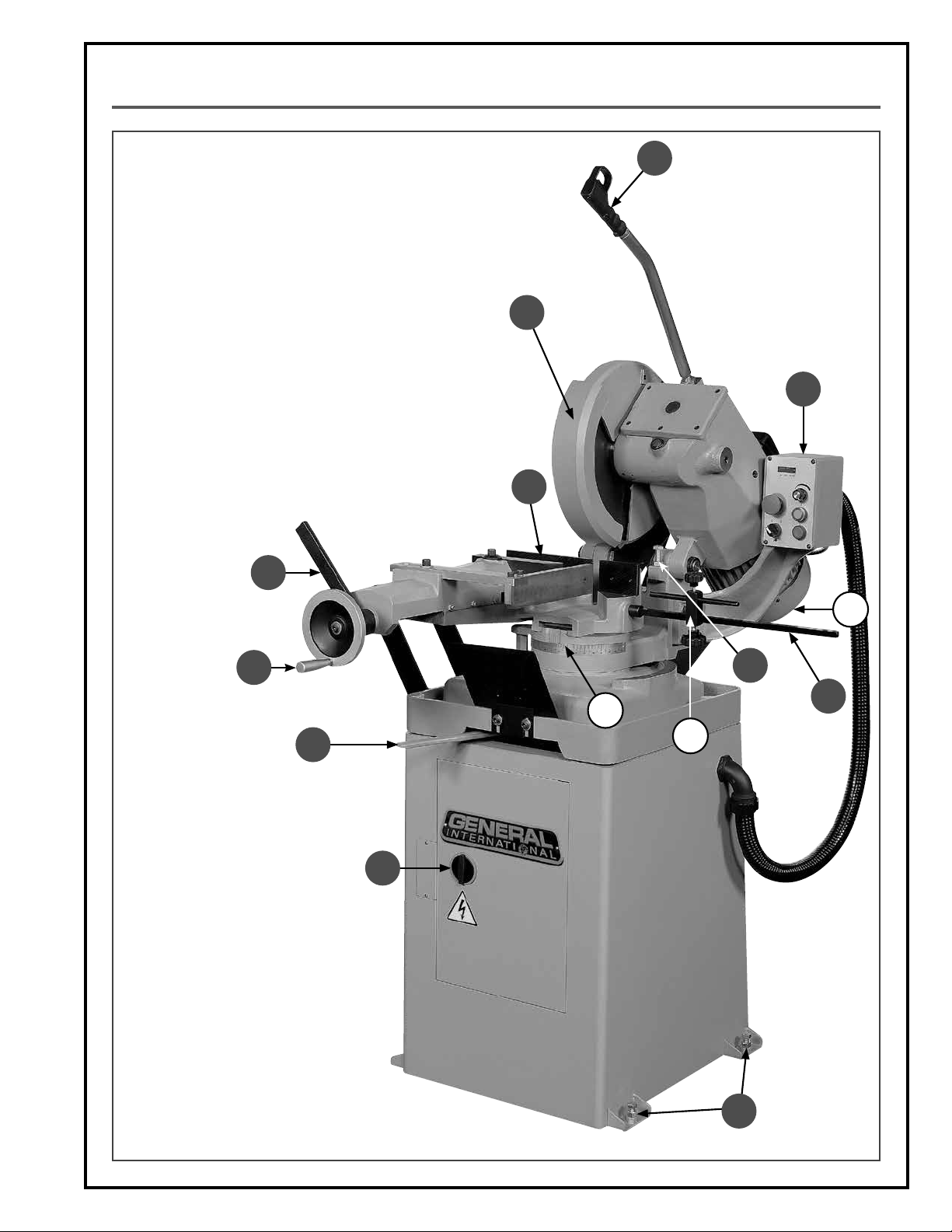
IDENTIFICATION OF MAIN PARTS AND COMPONENTS
A. LEVELING BOLT (4)
B. ELECTRONIC INVERTER ACCESS DOOR
C. SWIVEL BASE LOCK LEVER
D. VISE HANDLE
E. QUICK LOCK LEVER
F. VISE
G. BLADE GUARD
H. DOWNFEED HANDLE
I. PANEL CONTROL
J. MOTOR
K. WORKPIECE STOP BAR
L. DEPTH STOP
M. MITER SCALE
N. WORKPIECE STOP
E
H
G
I
F
J
D
C
L
K
M
N
B
A
7
Page 8
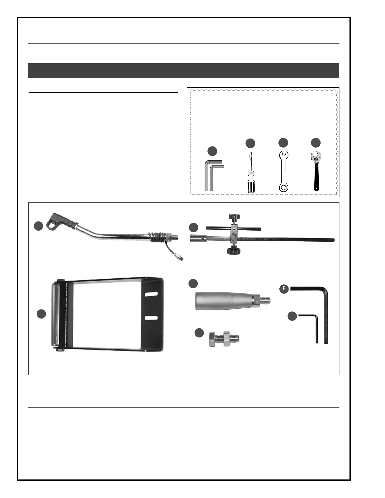
UNPACKING
Carefully unpack and remove the unit and its components from the box and check for missing or damaged items
as per the list of contents below.
NOTE: PLEASE REPORT ANY DAMAGED OR MISSING ITEMS TO YOUR GENERAL® INTERNATIONAL DISTRIBUTOR IMMEDIATELY.
LIST OF CONTENTS QTY
A. DOWNFEED HANDLE ............................................................... 1
B. WORKPIECE STOP ASSEMBLY .................................................. 1
C. TABLE EXTENSION ROLLER ....................................................... 1
D. VISE HANDLE ............................................................................ 1
E. HEX HEAD BOLT W/NUT ........................................................... 4
F. 10 MM ALLEN KEY ................................................................... 1
G. 4 MM ALLEN KEY ..................................................................... 1
A
ADDITIONAL REQUIREMENTS FOR SET UP
A. 5 & 6 MM ALLEN KEYS
B. PHILLIPS SCREWDRIVER
C. 12 MM WRENCH
D. WRENCH
B
A
B
C D
D
C
E
F
G
BASIC FUNCTIONS
This General International model 60-350 14” slow speed cold cut saw is designed for multipurpose cutting applications in all types of metal fabrication shops.
With the correct carbide or hi-speed steel blade, the built-in coolant system, and its low rpm blade speed this unit
is designed to produce cleaner more accurate cuts, as compared to abrasive wheels, on a variety of materials
including, aluminum, steel, brass and other work pieces of various sizes and profiles.
8
Page 9
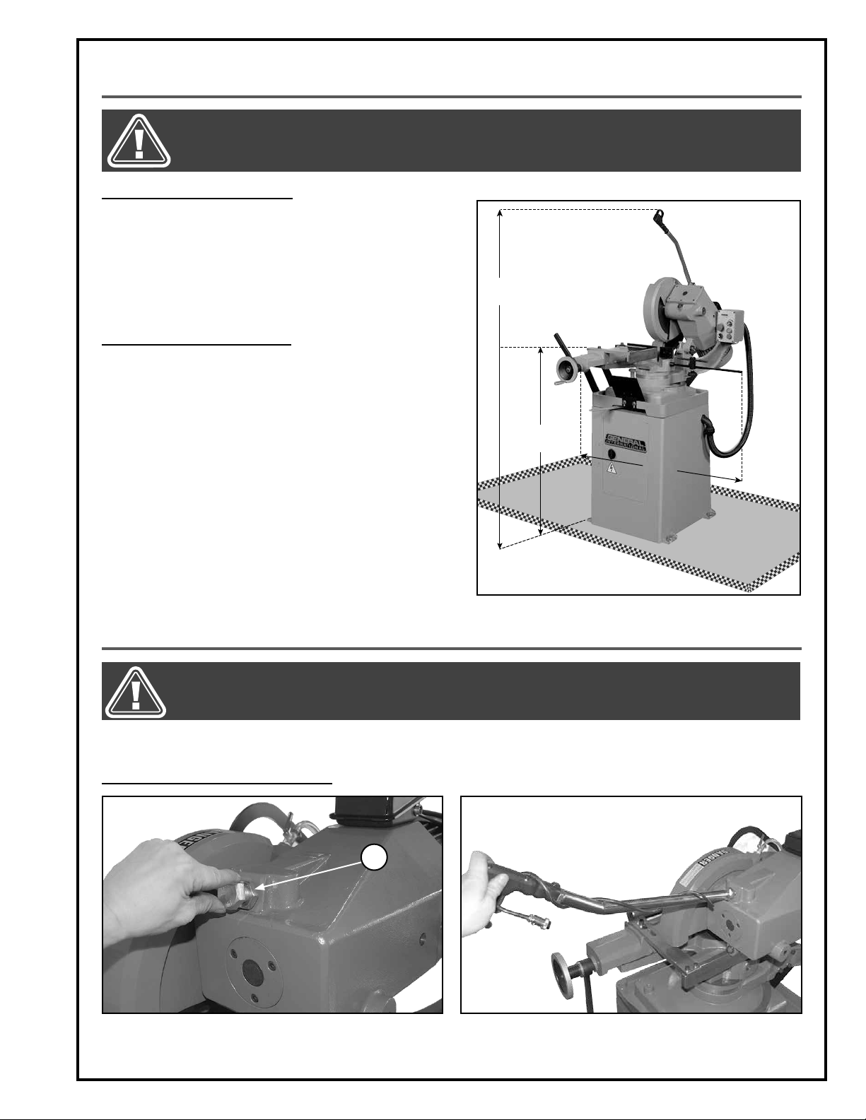
PLACEMENT WITHIN THE SHOP / SAFETY ZONE
THIS COLD CUT SAW MODEL 60-350 IS HEAVY. DO NOT OVER-EXERT. A HOIST OR FORKLIFT WITH STRAPS SHOULD BE
USED TO LIFT THIS MACHINE. TO LIMIT THE RISK OF SERIOUS INJURY OR DAMAGE TO THE MACHINE, ANY EQUIPMENT
USED TO LIFT THIS MACHINE SHOULD HAVE A RATED CAPACITY IN EXCESS OF 550 LBS (250 KG).
PLACEMENT WITHIN THE SHOP
This machine should be installed and operated only on a
solid, flat and stable floor that is able to support the weight
of the machine (550 lbs - 250 kg) and the operator. Using
the dimensions shown as a guideline, plan for placement
within your shop that will allow the operator to work unencumbered and unobstructed by foot traffic (either passing shop visitors or other shop workers) or other tools or
machinery.
ESTABLISHING A SAFETY ZONE
For shops with frequent visitors or multiple operators, it is
advisable to establish a safety zone around shop machinery. A clearly defined ”no-go” zone on the floor around
each machine can help avoid accidents that could
cause injury to either the operator or the shop visitor.
It is advisable to take a few moments to either paint (using
non-slip paint) or using tape, define on the floor the limits
or perimeter of each machines safety zone. Take steps to
ensure that all operators and shop visitors are aware that
these areas are off limits whenever a machine is running
for everyone but the individual operating the unit.
72"
40"
39"
ASSEMBLY INSTRUCTIONS
BEFORE ASSEMBLING, MAKE SURE THAT THE SWITCH IS IN THE ”OFF” POSITION AND THAT THE POWER CORD IS
UNPLUGGED. DO NOT PLUG IN OR TURN ON THE MACHINE UNTIL YOU HAVE COMPLETED THE ASSEMBLY AND
INSTALLATION STEPS DESCRIBED IN THIS SECTION OF THE MANUAL.
For your convenience this saw is shipped from the factory partially assembled and requires only minimal assembly and
set up before being put into service.
INSTALLING THE DOWNFEED HANDLE
A
1. Remove plug A by hand.
2. Screw the downfeed handle into the gear box in
place of the plug.
9
Page 10

BEFORE ASSEMBLING, MAKE SURE THAT THE SWITCH IS IN THE ”OFF” POSITION AND THAT THE POWER CORD IS
UNPLUGGED. DO NOT PLUG IN OR TURN ON THE MACHINE UNTIL YOU HAVE COMPLETED THE ASSEMBLY AND
INSTALLATION STEPS DESCRIBED IN THIS SECTION OF THE MANUAL.
INSTALLING THE DOWNFEED HANDLE (CONTINUED)
3. Secure the downfeed handle by tightening two
4. Turn the handle so that the trigger points up.
jam nuts with a wrench.
A
5. Secure the handle by tightening jam nut A.
INSTALLING A BLADE
There are a variety of different types of blades on the market to suit various cutting applications. Your results may vary
based on usage, experience and personal preference. Ask your local tool dealer for suggestions for 14” x 1 1/4” (350 X
32 mm) cold cut blades. Please note that General International offers an optional a 14” hi-speed steel general purpose
blade (#60-355).
Note: See section ”Parts list and diagrams” for the blade specifications.
6. Connect the trigger control cable to the electrical
box on the motor as shown.
1. To install a blade, remove the screw A on the guard
using a 4 mm Allen key.
10
A
2. Detach the guard arm and slide open the guard.
Page 11

BEFORE ASSEMBLING, MAKE SURE THAT THE SWITCH IS IN THE ”OFF” POSITION AND THAT THE POWER CORD IS
UNPLUGGED. DO NOT PLUG IN OR TURN ON THE MACHINE UNTIL YOU HAVE COMPLETED THE ASSEMBLY AND
INSTALLATION STEPS DESCRIBED IN THIS SECTION OF THE MANUAL.
INSTALLING A BLADE (CONTINUED)
3. Remove the blade flange screw using a 10 mm Al-
len wrench. Turn clockwise as shown.
B
5. Install the blade on the blade holder, making sure
that the blade is installed with the teeth pointing
down as shown B.
4. Remove the blade flange from the blade holder.
C
C
6. Hold the blade against the blade holder making
sure it sits flush, then align the two mounting holes C
with the corresponding holes on the blade holder.
7. Re-install the blade flange and thread the mount-
ing screws on 2-3 turns only.
A
8. Align the two pins on the blade flange with the corre-
sponding holes in the blade and the blade holder A.
11
Page 12

BEFORE ASSEMBLING, MAKE SURE THAT THE SWITCH IS IN THE ”OFF” POSITION AND THAT THE POWER CORD IS
UNPLUGGED. DO NOT PLUG IN OR TURN ON THE MACHINE UNTIL YOU HAVE COMPLETED THE ASSEMBLY AND
INSTALLATION STEPS DESCRIBED IN THIS SECTION OF THE MANUAL.
INSTALLING A BLADE (CONTINUED)
9. Push on the flange to seat it flush against the blade. 10. Tighten the mounting screw counterclockwise to
secure the flange and the blade to the holder.
B
11. Lower the blade guard and re-install the blade
guard arm on its pivot B as shown.
INSTALLING THE TABLE EXTENSION ROLLER
1. Remove the two screws and flat washers on the left
side of the machine with a 6 mm Allen key.
12. Secure the arm to the blade guard using a 5 mm
Allen key.
2. Align the roller slots with the holes in the machine
and secure it in place with screws and washers.
Note: Adjust the support roller height as needed along the
slotted mounting holes.
12
Page 13

BEFORE ASSEMBLING, MAKE SURE THAT THE SWITCH IS IN THE ”OFF” POSITION AND THAT THE POWER CORD IS
UNPLUGGED. DO NOT PLUG IN OR TURN ON THE MACHINE UNTIL YOU HAVE COMPLETED THE ASSEMBLY AND
INSTALLATION STEPS DESCRIBED IN THIS SECTION OF THE MANUAL.
INSTALLING THE WORKPIECE STOP
1. Remove the workpiece stop support using a 5 mm
Allen key. Insert the support into the workpiece
mounting hole located in the base of the cutting
head.
3. Insert the end of the workpiece stop arm all the
way into the support.
2. Using a rubber mallet, tap gently on the support to
insert it all the way into the mounting hole.
4. Retighten the cap screw to lock the workpiece stop
arm in place.
D
6. Turn the workpiece stop by hand to place to it in
the vertical position.
C
A
B
Tip: The workpiece stop has two adjustment points: Position
the main adjustment block A that slides on the graduated
bar using lock knob B. The smaller fine-tuning adjustment
bar C can be set using lock knob D.
13
Page 14

BEFORE ASSEMBLING, MAKE SURE THAT THE SWITCH IS IN THE ”OFF” POSITION AND THAT THE POWER CORD IS
UNPLUGGED. DO NOT PLUG IN OR TURN ON THE MACHINE UNTIL YOU HAVE COMPLETED THE ASSEMBLY AND
INSTALLATION STEPS DESCRIBED IN THIS SECTION OF THE MANUAL.
INSTALLING THE VISE HANDLE
1. Screw the handle into the mounting hole on the
vise handwheel
2. Tighten the handle using a 12 mm wrench.
BASIC ADJUSTMENTS & CONTROLS
TO REDUCE THE RISK OF SHOCK OR FIRE DO NOT OPERATE THE UNIT WITH A DAMAGED POWER CORD OR PLUG. REPLACE DAMAGED CORD OR PLUG IMMEDIATELY. TO AVOID UNEXPECTED OR UNINTENTIONAL START-UP, MAKE SURE
THE POWER SWITCH IS IN THE OFF POSITION BEFORE CONNECTING TO A POWER SOURCE.
CONNECTING TO A POWER SOURCE
Once the assembly steps have been completed, plug
the power cord into an appropriate outlet.
Refer back to the section entitled ”Electrical Require
ments” and make sure all requirements and grounding
instructions are followed.
When cutting operations have been completed, un
plug the saw from the power source.
MAGNETIC SWITCH
This machine is equipped with a magnetic safety switch
designed to protect the unit and the user from power
surges, power outages or unintentional start-up.
The switch assembly is equipped with a green ”start”
button A, a red ”stop” button B and a emergency stop
button with twist lock-out device C. Once this button has
been pressed, the machine can only be restarted by
turning the button to the right to release the stop button, E.
The coolant system pump is controlled using switch D.
To start the pump, turn the switch to the right. To stop the
pump, turn the switch to the left.
-
-
SWITCH OFF
C
TO AVOID UNEXPECTED OR UNINTENTIONAL START-UP, MAKE SURE
THAT THE POWER SWITCH IS IN
THE OFF POSITION BEFORE CONNECTING TO A POWER SOURCE.
E
A
D
14
B
Page 15

MAKE SURE THE MACHINE HAS BEEN TURNED OFF AND UNPLUGGED FROM THE POWER SOURCE BEFORE PERFORMING ANY MAINTENANCE OR ADJUSTMENTS.
BLADE SPEED ADJUSTMENT
The blade speed ranges from 24 to 120 rpm. The blade
speed control knob is located on the control box, just
above the on button.
B
A
- Turn the knob A clockwise to increase the blade speed.
- Turn the knob A counterclockwise to decrease the
blade speed.
Blade speed will be appear on the digital speed display B.
ELECTRONIC SYSTEM PROTECTOR
The electronic inverter of this machine is equipped with an overload protection feature. To prevent an electrical
overload from damaging the motor, in the event of a spike in line voltage or amperage draw, the internal electronic system protector will automatically cut off power to the motor and display an error message indicating the
cause of the electrical problem.
Common causes of such overloads:
• Overworking the motor by forcing the saw, particularly with thicker denser material, thereby causing an increase in power consumption and a spike in amperage draw.
• An electrical extension cord that is too long or not the correct gauge of wire, which can also cause an increase in amperage draw. If an electric extension cord must be used, follow the instructions and refer to the
chart in the electrical requirements section at the beginning of this manual.
• Overworked circuit caused by operating on a circuit that is close to its amperage draw capacity. Make sure
the circuit being used is capable of handling the amperage draw from this machine as well as any other
electrical devices operating on the same circuit. If you are unsure, consult a qualified electrician.
If the digital speed display on the control box indicates one of the error messages listed below*, wait a few seconds until the message disappears from the screen, then proceed as follows to reset the electronic system protector in and restart the machine.
ERROR MESSAGES ON THE DIGITAL SPEED DISPLAY
OVERCURRENT OVER VOLTAGE LOW VOLTAGE OVERLOAD
D
C
1. Remove the box control cover using a 3 mm Allen
key.
* If the problem persists, refer to the inverter owner's manual after the intervention or for any other error message.
2. Press button C (STOP) then press button D (RUN).
Re-install the box cover before restarting the machine.
15
Page 16

MAKE SURE THE MACHINE HAS BEEN TURNED OFF AND UNPLUGGED FROM THE POWER SOURCE BEFORE PERFORMING ANY MAINTENANCE OR ADJUSTMENTS.
ADJUSTING THE CUT ANGLE
A
B
1. To unlock the swivel base push lever A to the left as
shown.
ADJUSTING THE SWIVEL BASE LOCK LEVER
C
1. If the lever does not lock the base securely, loosen
the screw C with a 6 mm Allen key while holding the
lever in place on its shaft.
ADJUSTING AND USING THE VISE
2. Refer to the graduated scale B at the base of the
saw head to set the blade to the required angle.
2. Turn the lever to the right, and then retighten the
screw A. Make sure the lever locks the swivel base.
If not, repeat steps 1 & 2.
D
1. Position the workpiece in the vise and secure it in
place using the vise handwheel D.
16
2. Lock the workpiece in place by turning the quick
locking lever to the left as shown.
Page 17

MAKE SURE THE MACHINE HAS BEEN TURNED OFF AND UNPLUGGED FROM THE POWER SOURCE BEFORE PERFORMING ANY MAINTENANCE OR ADJUSTMENTS.
ADJUSTING AND USING THE VISE (CONTINUED)
A
3. To adjust the vise jaw, loosen screw A with a 10 mm
Allen key. Slide the jaw right or left to the desired
position, then retighten screw A.
Note: Adjustment required for miter cuts.
ADJUSTING THE SAW HEAD STOPS
C
B
1. If the downfeed handle is difficult to reach in the
up position, loosen jam nut B with a 19 mm wrench,
then loosen bolt C until the desired handle height is
reached. Retighten jam nut B.
Note: Pull back the vise assembly to allow the rotation of
the saw head all way to the right, especially for miter cuts.
E
D
2. To adjust the saw head in the down position, loosen
jam nut D with a 19 mm wrench, then turn bolt E
clockwise or counterclockwise as per the adjustment desired. Retighten jam nut D.
IMMOBILIZING THE MACHINE
Machine vibration during operation may cause the
machine to move, particularly when installed on uneven surfaces.
The bolt-down tabs and anchor bolts F can be used to
help keep the machine immobilized by either lowering the bolts against the floor to act as another point of
contact with the floor, or for permanent installations, by
drilling into the floor and bolting the machine in place.
F
17
Page 18

OPERATING INSTRUCTIONS
CHECKLIST BEFORE STARTING
VERIFY ALL CHECK POINTS BEFORE STARTING. FAILURE TO COMPLY CAN RESULT IN SERIOUS INJURIES.
1. Make sure you and any assistants are wearing safe and appropriate workshop attire.
2. To reduce the risk of damage to the machine, as well as potential for personal injury, after initial set-up as well
as before each use, make sure that everything is securely installed and that all fasteners and moving parts on
this machine are locked in place before starting the machine.
3. Make sure to have on safety glasses as well as hearing or/and respiratory protection at all times when using the
machine.
4. Check the level of coolant in the tank and fill it as necessary. The maximum level is 5 liters.
5. Use only recommended parts and accessories. The use of parts or accessories NOT recommended by
GENERAL® INTERNATIONAL may result in a risk of injury or damage to the machine.
6.
Be sure that adjusting wrenches, tools, drinks and other clutter are removed from the machine and/or the
table surface before operating.
OPERATIONS STEP-BY-STEP
NEVER USE THE SAW WITHOUT ALL GUARDS AND COVERS IN PLACE. BEFORE STARTING THE SAW BE SURE THAT THE
BLADE IS NOT ALREADY IN CONTACT WITH THE WORKPIECE.
1. Trace the cutting line on your workpiece with a pen-
cil and clamp the material firmly in the vise jaws.
Make sure the workpiece is properly secured in the
vise.
Note: Use the work stop to quickly and accurately cut multiple pieces of stock to the same length.
2. Press button A to start the machine. Adjust the blade
speed with knob B.
3. Turn on the coolant pump by turning switch C to the
right and opening the coolant valve D.
4. Press on the downfeed handle trigger while smoothly lowering the saw head.
5. Once the cut is completed, raise the head and
release the trigger. Turn OFF the pump by turning
switch C to the left.
6. Press button E to turn off the machine.
7. Carefully remove the workpiece from the vise.
BURN DANGER: DO NOT USE BARE HANDS TO TOUCH
THE WORKPIECE AT THE CUT LOCATION UNTIL IT HAS
COOLED.
C
D
OPENED
CLOSED
B
A
E
Note: Before operation, see the chart below regarding the
cutting capacity of your machine based on the size and
shape of the workpiece.
WORKPIECE
Straight cut 3 3/8” (85 mm) 4 3/4” (120 mm) 4” X 4” (102 x 102 mm) 6 1/8” X 3 1/2” (155 x 90 mm)
Cut at 45° 3” (75 mm) 3 3/4” (95 mm) 3 1/8” X 3 1/8” (80 x 80 mm) 3 1/8” X 2 3/4” (80 x 70 mm)
18
D
CUTTING CAPACITY
Page 19

MAKE SURE THE MACHINE HAS BEEN TURNED OFF AND UNPLUGGED FROM THE POWER SOURCE BEFORE PERFORMING ANY MAINTENANCE OR ADJUSTMENTS.
MAINTENANCE
CLEANING
For optimum performance from your machine follow this maintenance schedule and refer to any specific instructions given in this section. After using your machine, sweep up and discard any excess metal chips and debris.
REGULAR MAINTENANCE TASK FREQUENCY
DAILY WEEKLY MONTHLY 2 x YEAR
• Basic cleaning of the
machine
• Fill the coolant tank if
necessary
• Inspect the blade
• Leave the saw head
in the ”up” position
to reduce tension on
the return spring
• Check the splash
guards and verify
that the emergency
stop works properly
CHANGING THE GEAR BOX OIL
• Thoroughly clean the
• Clean and grease the
•
machine, including
the tank and filter
vise screw and the
slides
Clean the blade holder
• Make sure all the fasteners are tightened
• Inspect the condition of
all guards
• Grease the saw head
pivot shaft
• Change the gear
box oil
A
1. Position the saw head in the down position. Re-
move oil plug A with an18 mm wrench to drain the
gear box. Once the used oil is drained, re-install the
plug A.
Note: To avoid damage do not overtighten the plastic plug A.
2. Remove the downfeed handle using a wrench to
access the filling hole.
3. Fill the gear box with 1,5 liters of 460 grade gear
oil. Re-install the downfeed handle (see section ”Installing the downfeed handle”).
19
Page 20

MAKE SURE THE MACHINE HAS BEEN TURNED OFF AND UNPLUGGED FROM THE POWER SOURCE BEFORE PERFORMING ANY MAINTENANCE OR ADJUSTMENTS.
FUSE REPLACEMENT
1. Shut off the power source by turning the lock-out
safety switch counterclockwise.
latch.
2. Remove the two front plate screws with a Phillips
screwdriver.
4. Pull back the latch as shown.3. Remove the front plate to access the cabinet door
5. Open the latch and then open the cabinet door.
Note: The cabinet door can't be opened if the power source
is not shut off with the safety lock-out switch (step 1).
20
6. Remove the used fuse and replace with one of the
same amperage. Then close the cabinet door to
restart the machine.
Page 21

DIAGRAM
21
Page 22

PARTS LIST
IMPORTANT: When ordering replacement parts, always give the model number, serial number of the
machine and part number. Also a brief description of each item and quantity desired.
PART # DESCRIPTION SPECIFICATIONS QTY
60350-A01 BASE LOCK LEVER 1
60350-A02 NYLOCK NUT 1
60350-A03 CAP SCREW 1
60350-A04 CAP SCREW M8 X 25 2
60350-A05 WASHER 5/16” 2
60350-A06 CONNECTOR 1
60350-A07 RUBBER GASKET 1
60350-A08 HEAD BASE 1
60350-A09 CAP SCREW M8 X 16 2
60350-A10 WASHER 5/16” 2
60350-A11 SPLASH GUARD PLATE 1
60350-A12 SCREW 2
60350-A13 SPLASH GUARD 2
60350-A14 CAP SCREW 2
60350-A15 ROLLER 1
60350-A16 ROLLER BRACKET 1
60350-A17 HANDWHEEL 1
60350-A18 SUPPORT ROD 1
60350-A19 SWIVEL BASE 1
60350-A20 SLIDE BASE 1
60350-A21 RETENTION RING 1
60350-A22 CENTER SHAFT 1
60350-A23 CAP SCREW M8 X 20 1
60350-A24 WASHER M10 1
60350-A25 HANDLE 1
60350-A26 SET SCREW 1
60350-A27 BEARING COVER 1
60350-A28 BEARING 1
60350-A29 BUSHING 1
60350-A30 SPRING 1
60350-A31 LEAD SCREW 1
60350-A32 QUICK LOCK LEVER 1
60350-A33 SLIDING VISE 1
60350-A34 SET SCREW 3
60350-A35 WASHER 3
60350-A36 NUT 3
60350-A37 GIB 1
60350-A38 SLIDING JAW 1
60350-A39 FIXED VISE (SMALL) 1
60350-A40 CAP SCREW M5 X 25 3
60350-A41 SMALL JAW 1
60350-A42 GROOVED JAW 1
60350-A43 STOP PLATE 1
60350-A44 CAP SCREW M8 X 20 2
60350-A45 CAP SCREW M8 X 25 2
60350-A46 PLATE (VISE) 1
60350-A47 CAP SCREW M8 X 25 1
60350-A48 WASHER 1
60350-A49 DUST PLATE 1
60350-A50 MOUNTING PLATE 1
60350-A51 SCREW 1
60350-A52 SPRING 1
60350-A53 LOWER PIVOT ARM 1
60350-A54 WASHER 2
22
Page 23

PARTS LIST
IMPORTANT: When ordering replacement parts, always give the model number, serial number of the
machine and part number. Also a brief description of each item and quantity desired.
PART # DESCRIPTION SPECIFICATIONS QTY
60350-A55 CAP SCREW 2
60350-A56 NUT 1
60350-A57 WASHER 1
60350-A58 LINK PLATE W/THREAD 1
60350-A59 UPPER PIVOT ARM 1
60350-A60 CAP SCREW M6 X 12 1
60350-A61 WASHER 1/4” 1
60350-A62 CAP SCREW M8 X 20 3
60350-A63 WASHER 5/16” 2
60350-A64 LINK PLATE 1
60350-A65 RETENTION RING 1
60350-A66 BLADE GUARD 1
60350-A67 SCREW M5 X 10 7
60350-A68 PLATE 1
60350-A69 GASKET 2
60350-A70 BLADE COVER 1
60350-A71 PLATE 1
60350-A72 CAP SCREW M12 X 35 1
60350-A73 FLANGE 1
60350-A74 SAW BLADE (OPTIONAL #60-355) 350MM 1
60350-A75 BLADE HOLDER 1
60350-A76 OIL SEAL 50.72.8. 1
60350-A77 TAPERED ROLLER BEARING 32008 2
60350-A78 SPINDLE SLEEVE 1
60350-A79 SPROCKET WASHER 1
60350-A80 NYLOCK NUT 1
60350-A81 SPACER 1
60350-A82 WORM GEAR 1
60350-A83 BUSHING 1
60350-A84 PLATE STOP 1
60350-A85 LOCK WASHER 2
60350-A86 NYLOCK NUT 1
60350-A87 MACHINE HEAD 1
60350-A88 BEARING 6301 1
60350-A89 WORM SHAFT 1
60350-A90 BEARING 5305 1
60350-A91 OIL SEAL 25 X 52 X 10 1
60350-A92 COUPLING 1
60350-A93 MOTOR 3HP 1
60350-A94 STRAIN RELIEF 2
60350-A95 CONTROL WIRE 1
60350-A96 NUT M20 1
60350-A97 CONTROL HANDLE LEVER 1
60350-A98 NUT M16 1
60350-A99 TRIGGER SWITCH HANDLE 1
60350-A100 OIL GAUGE 1
60350-A101 GASKET 1
60350-A102 OIL RING 5 X 55 2
60350-A103 CASTING PLUG 1
60350-A104 CAP SCREW M6 X 20 3
60350-A105 NUT M10 1
60350-A106 SET SCREW M10 X 35 1
60350-A107 OIL SEAL 1
60350-A108 WORKPIECE STOP SUPPORT 1
23
Page 24

PARTS LIST
IMPORTANT: When ordering replacement parts, always give the model number, serial number of the
machine and part number. Also a brief description of each item and quantity desired.
PART # DESCRIPTION SPECIFICATIONS QTY
60350-A109 LOCK KNOB 5 X 55 1
60350-A110 WORKPIECE STOP BRACKET 1
60350-A111 UPPER ROD 1
60350-A112 LOWER ROD 1
60350-A113 LOCK KNOB 1
60350-A114 NYLOCK NUT 2
60350-A115 SHAFT (RIGHT) 1
60350-A116 SHAFT (LEFT) 1
60350-A117 BUSHING 1
60350-A118 HEX HEAD BOLT 2
60350-A119 NUT 2
60350-A120 CONTROL BOX ARM 1
60350-A121 DIGITAL DISPLAY 1
60350-A122 SPEED CONTROL KNOB 1
60350-A123 CONTROL COVER 1
60350-A124 PUMP SELECTION SWITCH 1
60350-A125 EMERGENCY SWITCH 1
60350-A126 START BUTTON 1
60350-A127 STOP BUTTON 1
60350-A128 SCREW 4
60350-A129 CAP SCREW 2
60350-A130 SUPPORT PLATE 1
60350-A131 TRANSMISSION WIRE 1
60350-A132 SPLASH GUARD PLATE 1
BLADE SPECIFICATIONS
• A (blade diameter): 14”/350 mm
• B (distance between pin hole centers): 63 mm
• C (flange diameter): 89 mm
• D (center hole/bore diameter): 32 mm
• E (number of pin holes): can be 2 or 4
• F (hole diameter): 11 mm
E
A
D
B C
F
24
Page 25

DIAGRAM & PARTS LIST
CABINET AND PUMP
IMPORTANT: When ordering replacement parts, always give the model number, serial number of the
machine and part number. Also a brief description of each item and quantity desired.
PART # DESCRIPTION SPECIFICATIONS QTY
60350-B01 CABINET 1
60350-B02 NUT M6 4
60350-B03 WASHER 1/4” 4
60350-B04 SUPPORT PLATE 1
60350-B05 WASHER 1/4” 4
60350-B06 HEX HEAD BOLT M6 X 15 4
60350-B07 COOLANT TANK 1
60350-B08 HOSE 1
60350-B09 HOSE CLAMP 1
60350-B10 WASHER 1/4” 2
60350-B11 CAP SCREW M6 X 16 2
60350-B12 COOLANT PUMP 1
60350-B13 HOSE CONNECTOR 1
60350-B14 HOSE CLAMP 1
60350-B15 HOSE 3/8” 1
60350-B16 HOSE CLAMP 1
60350-B17 VALVE 1
60350-B18 WIRE 1
60350-B19 HEX HEAD BOLT M6 X 15 4
60350-B20 WASHER 1/4” 4
60350-B21 HEX HEAD BOLT M6 X 15 2
60350-B22 WASHER 1/4” 2
PART # DESCRIPTION SPECIFICATIONS QTY
60350-B23 TANK SUPPORT PLATE 1
60350-B24 PROTECTOR PLATE 1
60350-B25 GOOSENECK TUBE 1
60350-B26 HEX CAP BOLT 4
60350-B27 WASHER 4
60350-B28 NUT 4
60350-B29 ELECTRICAL BOX 1
60350-B30 POWER CORD 1
60350-B31 INVERTER 1
60350-B32 SAFETY DOOR SWITCH 1
60350-B33 CAP SCREW 2
60350-B34 WASHER 2
60350-B35 TRANSFORMER 1
60350-B36 FUSE AND FUSE HOLDER 1
60350-B37 RELAY 2
60350-B38 TERMINAL PLATE 1
60350-B39 CIRCUIT BOARD 1
60350-B40 STRAIN RELIEF 2
60350-B41 PLATE 2
60350-B42 PHILIPPS SCREW 1
60350-B43 PLATE 1
60350-B44 COLLAR 1
25
Page 26

WIRING DIAGRAM
21
26
Page 27

NOTES
27
Page 28

8360 Champ-d’Eau, Montreal (Quebec) Canada H1P 1Y3
Tel.: (514) 326-1161
Fax: (514) 326-5565 - Parts & Service / (514) 326-5555 - Order Desk
orderdesk@general.ca
www.general.ca
Follow us:
 Loading...