

Page 1
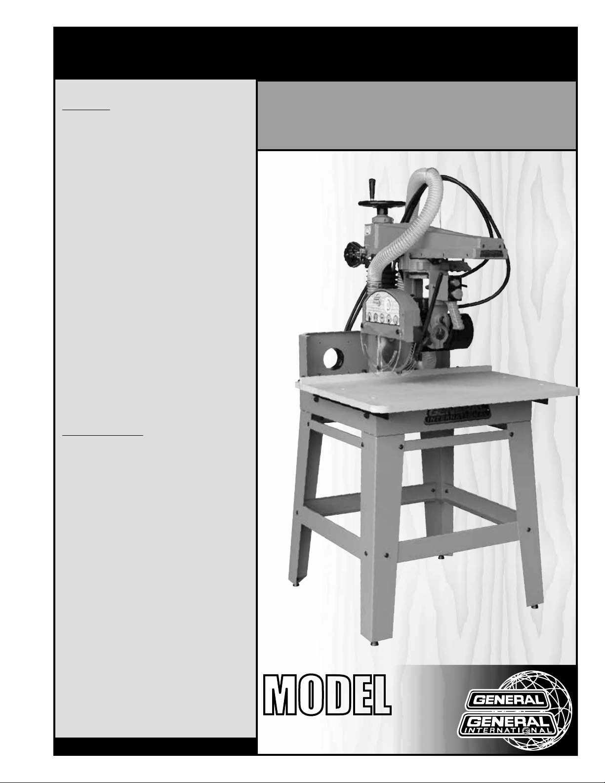
SETUP & OPERATION MANUAL
FEATURES
Industrial rated quality and versatile design
allows for standard crosscuts, as well as bevels,
miters, and head swivels for rip cutting applications.
Powerful 2 HP 220V single phase (M1) or 3 HP
220V 3-phase (M2) TEFC motor.
Cast-iron frame, heavy steel column and sturdy
easy to assemble all-steel stand for perfect
alignment and stability.
Precision adjustable indexing with positive stops
at 90º, 45º and 22.5º.
See-through blade cover with anti-kickback attachment and splitter.
Magnetic switch with overload protection and a
lock-out key to prevent unauthorized use.
Automatic mechanical brake stops the blade in
seconds upon shutdown.
Dual 4” dust ports above the table, and a 2” dust
port on the rear of the blade cover.
12” negative rake, multi-purpose combination
blade included.
Adjustable tension cutterhead / carriage return
spring to smoothly retract the motor and carriage back to the start position.
5/8” arbor with 1” spacer bushing included.
Replaceable steel guide ways.
Laser included.
12” RADIAL ARM SAW
SPECIFICATIONS
• Blade diameter
12” (305 mm)
• Arbor diameter (with 1” spacer bushing included)
5/8” (16 mm)
• Maximum depth of cut at 90°
3” (76 mm) - with 12” blade
2” (50 mm) - with 10” blade
• Maximum depth of cut at 45°
2” (50 mm) - with 12” blade
• Maximum crosscut capacity (with 12” blade)
16” (407 mm) - in 1” thick
• Maximum rip capacity (with 12” blade)
26 3/8” (670 mm)
• Dado capacity
13/16” (21 mm)
• Table height
36 3/4” (935 mm)
• Table size
27 1/2” x 35 3/8” (700 x 900 mm)
• Overall dimensions (l x w x h)
35 3/4” x 43 1/4” x 70 7/8” (900 x 1100 x 1800 mm)
• Motor M1
2 HP, 220 V, 1 Ph, 9.4 A
• Motor M2
3 HP, 230 V, 3 ph, 9.5 A
• Weight (shipping / net)
580 lbs (263 kg) / 396 lbs (180 kg)
Version #2_Revision #1 - February 2016
© Copyright General International
MODEL
#
50-755 M1
Page 2

GENERAL® INTERNATIONAL
8360 Champ-d’Eau, Montreal (Quebec) Canada H1P 1Y3
Telephone (514) 326-1161 • Fax (514) 326-5555 • www.general.ca
THANK YOU
for choosing this General® International model 50-755 12” radial
arm saw. This radial arm has been carefully tested and inspected before shipment and if
properly used and maintained, will provide you with years of reliable service. For your safety,
as well as to ensure optimum performance and trouble-free operation, and to get the most
from your investment, please take the time to read this manual before assembling, installing
and operating the unit.
The manual’s purpose is to familiarize you with the safe operation, basic function, and features
of this radial arm saw as well as the set-up, maintenance and identification of its parts and
components. This manual is not intended as a substitute for formal woodworking instruction,
nor to offer the user instruction in the craft of woodworking. If you are not sure about the safety
of performing a certain operation or procedure, do not proceed until you can confirm, from
knowledgeable and qualified sources, that it is safe to do so.
Once you’ve read through these instructions, keep this manual handy for future reference.
DISCLAIMER: The information and specifications
in this manual pertain to the unit as it was supplied
from the factory at the time of printing. Because we
are committed to making constant improvements,
General® International reserves the right to make
changes to components, parts or features of this
unit as deemed necessary, without prior notice and
without obligation to install any such changes on
previously delivered units. Reasonable care is taken
at the factory to ensure that the specifications and
information in this manual corresponds with that of the
unit with which it was supplied. However, special orders
and ”after factory” modifications may render some
or all information in this manual inapplicable to your
machine. Further, as several generations of this model
radial arm saw and several versions of this manual may
be in circulation, if you own an earlier or later version of
this unit, this manual may not depict your unit exactly. If
you have any doubts or questions contact your retailer
or our support line with the model and serial number of
your unit for clarification.
Page 3

GENERAL® INTERNATIONAL WARRANTY
All component parts of General® International and Excalibur by General International® products
are carefully inspected during all stages of production and each unit is thoroughly inspected upon
completion of assembly.
Limited Lifetime Warranty
Because of our commitment to quality and customer satisfaction, General® International agrees to
repair or replace any part or component which upon examination, proves to be defective in either
workmanship or material to the original purchaser for the life of the tool. However, the Limited Lifetime
Warranty does not cover any product used for professional or commercial production purposes nor
for industrial or educational applications. Such cases are covered by our Standard 2-year Limited
Warranty only. The Limited Lifetime Warranty is also subject to the ”Conditions and Exceptions” as listed
below.
Standard 2-Year Limited Warranty
All products not covered by our lifetime warranty including products used in commercial, industrial
and educational applications are warranted for a period of 2 years (24 months) from the date of
purchase. General® International agrees to repair or replace any part or component which upon
examination, proves to be defective in either workmanship or material to the original purchaser during
this 2-year warranty period, subject to the ”conditions and exceptions” as listed below.
To file a Claim
To file a claim under our Standard 2-year Limited Warranty or under our Limited Lifetime Warranty,
all defective parts, components or machinery must be returned freight or postage prepaid to
General® International, or to a nearby distributor, repair center or other location designated by
General® International. For further details call our service department at 1-888-949-1161 or your local
distributor for assistance when filing your claim.
Along with the return of the product being claimed for warranty, a copy of the original proof of
purchase and a ”letter of claim” must be included (a warranty claim form can also be used and can
be obtained, upon request, from General® International or an authorized distributor) clearly stating the
model and serial number of the unit (if applicable) and including an explanation of the complaint or
presumed defect in material or workmanship.
CONDITIONS AND EXCEPTIONS:
This coverage is extended to the original purchaser only. Prior warranty registration is not required but
documented proof of purchase i.e. a copy of original sales invoice or receipt showing the date and
location of the purchase as well as the purchase price paid, must be provided at the time of claim.
Warranty does not include failures, breakage or defects deemed after inspection by
General® International to have been directly or indirectly caused by or resulting from; improper use,
or lack of or improper maintenance, misuse or abuse, negligence, accidents, damage in handling or
transport, or normal wear and tear of any generally considered consumable parts or components.
Repairs made without the written consent of General® International will void all warranty.
Page 4

TABLE OF CONTENTS
Rules for safe operation ..................................................................................................... 5
Electrical requirements ...................................................................................................... 6
Identification of main parts and components .................................................................. 7
Unpacking .......................................................................................................................... 8
Basic functions ................................................................................................................... 8
Placement within the shop ................................................................................................ 9
Assembly instructions ................................................................................................... 9-16
Assembling the stand ......................................................................................................................................... 9
Installing the machine on the stand .............................................................................................................. 11
Installing the handwheel handle .................................................................................................................... 12
Installing the blade ........................................................................................................................................... 13
Installing the batteries in the laser .................................................................................................................. 14
Installing the control box ................................................................................................................................. 15
Installing the dust hose and the dust ports .................................................................................................... 15
Installing the riving knife .................................................................................................................................. 16
Connecting the cutter head to the return spring ......................................................................................... 16
Basic adjustments and controls ................................................................................. 16-19
Connecting to a power source .......................................................................................................................16
Main On/Off magnetic switch ........................................................................................................................ 17
Overload protection ......................................................................................................................................... 17
Adjusting the cutter head height .................................................................................................................... 17
Positioning the cutter head on the arm ......................................................................................................... 18
Positioning the cutter head for miter cuts ...................................................................................................... 18
Pivoting the cutter head for ripping ............................................................................................................... 18
Pivoting the cutter head for bevel cross cutting ........................................................................................... 19
Adjusting the cutter head stop ........................................................................................................................ 19
Adjusting the return spring tension ................................................................................................................. 20
Adjusting the anti-kickback fingers ................................................................................................................ 20
Positioning the fence ........................................................................................................................................ 20
Connecting to a dust collector ....................................................................................................................... 21
Operating Instructions ................................................................................................ 21-25
Checklist before starting .................................................................................................................................. 21
Cutting the kerf in the work table .................................................................................................................... 21
Types of cuts ...................................................................................................................................................... 23
Maintenance ............................................................................................................... 25-31
Adjusting the work table parallel to the cutter head ................................................................................... 25
Squaring the blade to the table ..................................................................................................................... 27
Squaring the blade to the fence .................................................................................................................... 28
Adjusting the graduated scale for inboard ripping ..................................................................................... 29
Cutter head bearing adjustment ................................................................................................................... 30
Adjusting the base ............................................................................................................................................ 30
Adjusting the cutter head arm ........................................................................................................................ 31
Parts list & diagrams ................................................................................................... 32-40
Contact information ........................................................................................................ 42
Page 5

RULES FOR SAFE OPERATION
To help ensure safe operation, please take a moment to learn the machine’s applications and limitations,
as well as potential hazards. General
harmless for any injury that may result from the improper use of its equipment.
1. Do not operate the saw when tired, distracted, or un der the effects of drugs, alcohol or any medication
that impairs reflexes or alertness.
2. The work area should be well lit, clean and free
of debris.
3. Keep children and visitors at a safe distance when
the saw is in operation; do not permit them to ope rate the saw.
4. Childproof and tamper proof your shop and all ma chinery with locks, master electrical switches and
switch keys, to prevent unauthorized or unsupervised
use.
5. STAY ALERT! Give your work your undivided attention.
Even a momentary distraction can lead to serious
injury.
6. Fine particulate dust is a carcinogen that can be
hazardous to health. Work in a well-ventilated area
and whenever possible use a dust collector and
wear eye, ear and respiratory protection devices.
®
International disclaims any real or implied warranty and holds itself
13. Do not push or force stock into the blade. The saw
will perform better and more safely when working at
the rate for which it was designed.
14. To minimize risk of injury in the event of workpiece
kickback, never stand directly in-line with the blade
or in the potential kickback path of the workpiece.
15. Avoid working from awkward or off balance posi tions. Do not overreach while cutting; keep both feet
on floor. Use outfeed support or have an assistant
help when cutting long material.
16. Keep blade covers in place and in working or der. If a guard must be removed for maintenance or
cleaning, be sure it is properly re-attached before
using the tool again.
17. Never leave the machine running with the power on
when not in operation.
18. Use of parts and accessories NOT recommended
by General
malfunction or risk of injury.
®
International may result in equipment
7. Do not wear loose clothing, gloves, bracelets, neck laces or other jewelry while the saw is in operation.
Wear protective hair covering to contain long hair
and wear non-slip footwear.
8. Be sure that adjusting wren ches, tools, drinks and
other clutter are removed from the machine and/or
the table surface before operating.
9. Keep hands well away from the blade and all
moving parts. Use a brush, not hands, to clear away
chips and dust.
10. Be sure that the blade is securely installed and in the
proper cutting direction before operation.
11. Be sure the blade has gained full operating speed
before beginning to cut.
12. Always use a clean, properly sharpened blade. Dir ty or dull blades are unsafe and can lead to
accidents.
19. Never stand on machinery. Serious injury could
result if the tool is tipped over or if the blade is unin tentionally contacted.
20. Always disconnect tool from power before servicing
or changing accessories such as blades, or before
performing any maintenance, cleaning or adjust ments, or if the machine will be left unattended.
21. Make sure that switch is in ”OFF” position before plug ging in the power cord.
22. Make sure the tool is properly grounded. If equip ped with a 3-prong plug it should be used with a
three-pole receptacle. Never remove the third prong.
23. Do not use this saw for any purpose other than its
intended use. If used for other purposes,
General® International disclaims any real or im plied warranty and holds itself harmless for any in jury, which may result from that use.
5
Page 6
ELECTRICAL REQUIREMENTS
BEFORE CONNECTING THE MACHINE TO THE POWER SOURCE, VERIFY THAT THE VOLTAGE OF YOUR POWER
SUPPLY CORRESPONDS WITH THE VOLTAGE SPECIFIED ON THE MOTOR I.D. NAMEPLATE. A POWER SOURCE
WITH GREATER VOLTAGE THAN NEEDED CAN RESULT IN SERIOUS INJURY TO THE USER AS WELL AS DAMAGE
TO THE MACHINE. IF IN DOUBT, CONTACT A QUALIFIED ELECTRICIAN BEFORE CONNECTING TO THE POWER
SOURCE.
THIS TOOL IS FOR INDOOR USE ONLY. DO NOT EXPOSE TO RAIN OR USE IN WET OR DAMP LOCATIONS.
Note: Voltage requirements and amperage draw for M2 3-phase motor may not be fully
described in this manual. For complete electrical requirements refer to the motor I.D. name
plate on the machine. If in doubt consult a licensed qualified electrician before proceeding.
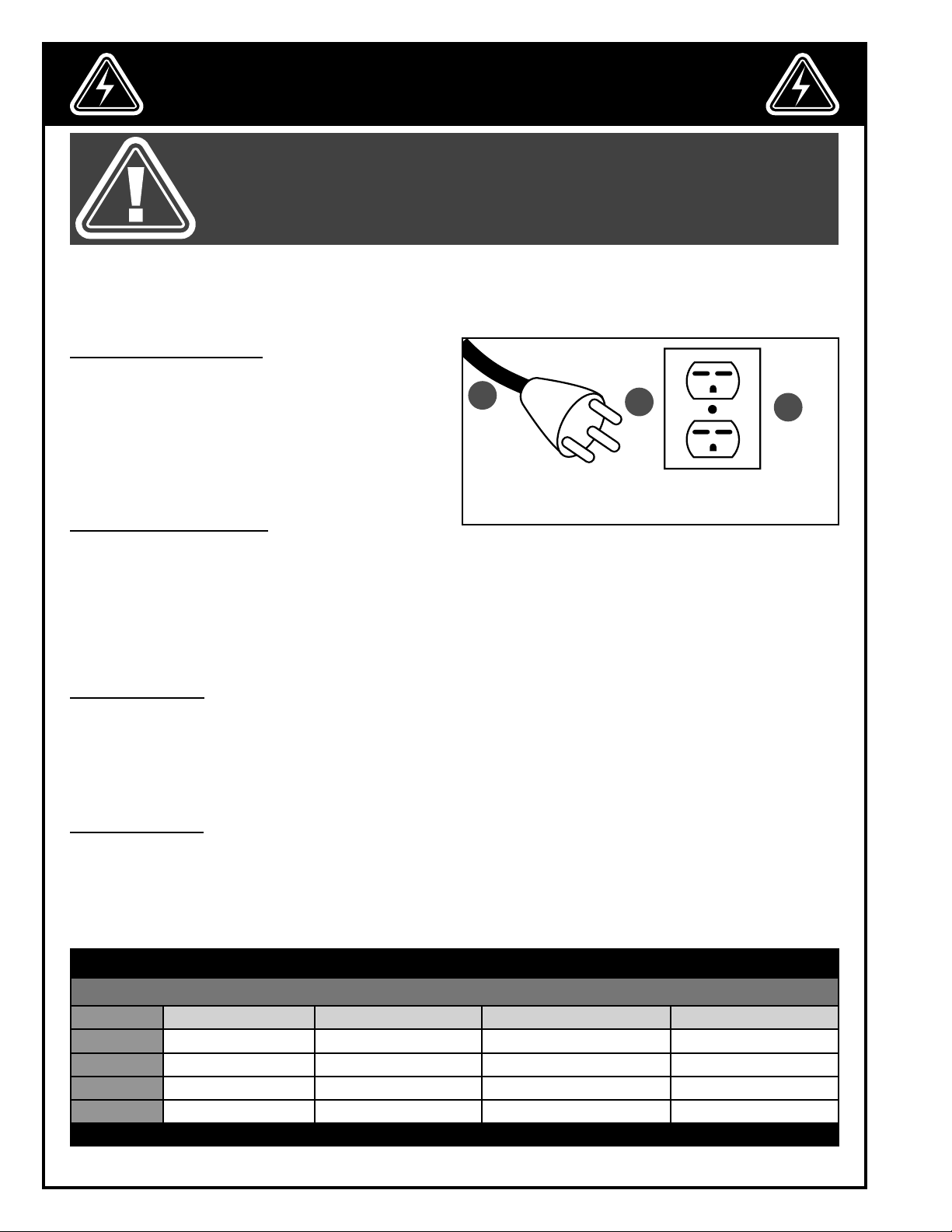
ELECTRICAL CONNECTIONS
Both a manual circuit breaker (or similar device) as well
as an electrical plug (similar to the one shown) are recommended and SHOULD BE INSTALLED BY A QUALIFIED
ELECTRICIAN.
Use locally approved wire A that includes a separate
grounding wire and a 3 prong grounding type plug B
with a matching receptacle C.
GROUNDING INSTRUCTIONS
In the event of an electrical malfunction or short circuit, grounding reduces the risk of electric shock to the operator. The motor of the ”M1” model of this machine is wired for 220 V single phase operation. As with many stationary
industrial type machines, because each installation situation is unique, this machine is supplied without a power
cord or plug. The installation of an appropriate power cord and plug must be performed by a qualified electrician.
The machine must be connected to an electrical source using a power cord that has a grounding wire, which
must also be properly connected to the grounding prong on the plug. The outlet must be properly installed and
grounded and all electrical connections must be made in accordance with all local codes and regulations.
A
B
C
CIRCUIT CAPACITY
Make sure that the wires in your circuit are capable of handling the amperage draw from your machine, as well as
any other machines that could be operating on the same circuit. If you are unsure, consult a qualified electrician.
If the circuit breaker trips or the fuse blows regularly, your machine may be operating on a circuit that is close to its
amperage draw capacity. However, if an unusual amperage draw does not exist and a power failure still occurs,
contact a qualified technician or our service department.
EXTENSION CORDS
The use of an extension cord is not generally recommended for 220 V equipment. If you find it necessary, use
only 3-wire extension cords that have 3-prong grounding plug and a matching 3-pole receptacle that accepts
the tool’s plug. Repair or replace a damaged extension cord or plug immediately. Make sure the cord rating is
suitable for the amperage listed on the motor I.D. plate. An undersized cord will cause a drop in line voltage resulting in loss of power and overheating. The accompanying chart shows the correct size extension cord to be used
based on cord length and motor I.D. plate amp rating. If in doubt, use the next heavier gauge.
TABLE - MINIMUM GAUGE FOR CORD
EXTENSION CORD LENGTH
AMPERES 50 feet 100 feet 200 feet 300 feet
< 5
6 to 10
10 to 12
12 to 16
*NR = Not Recommended
18 16 16 14
18 16 14 12
16 16 14 12
14 12 *NR *NR
6
Page 7
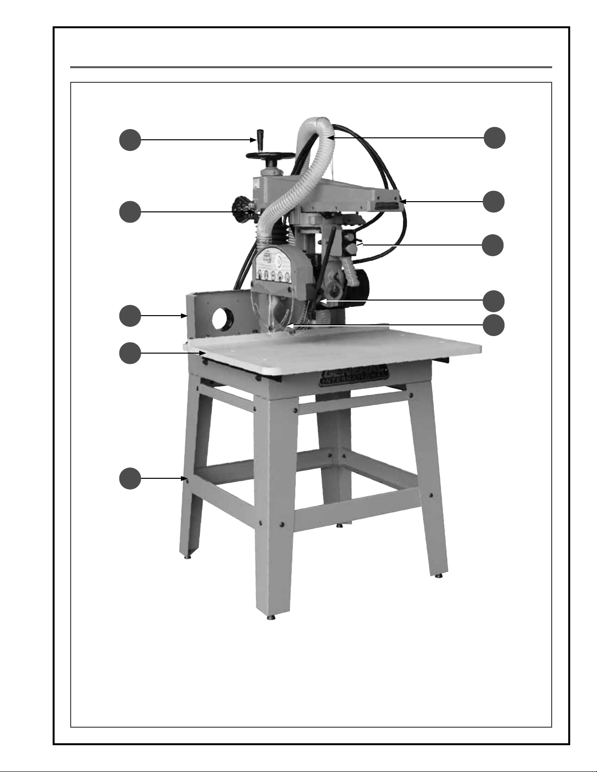
IDENTIFICATION OF MAIN PARTS AND COMPONENTS
E
D
C
B
F
G
H
I
J
A
A. STAND
B. WORK TABLE
C. DUST PORT SUPPORT
D. ADJUSTABLE TENSION RETURN SPRING
E. BLADE HEIGHT ADJUSTMENT HANDWHEEL
F. DUST HOSE
G. ARM
H. ON/OFF SWITCH
I. ANTI-KICKBACK FINGERS
J. SEE-THROUGH BLADE COVER
7
Page 8
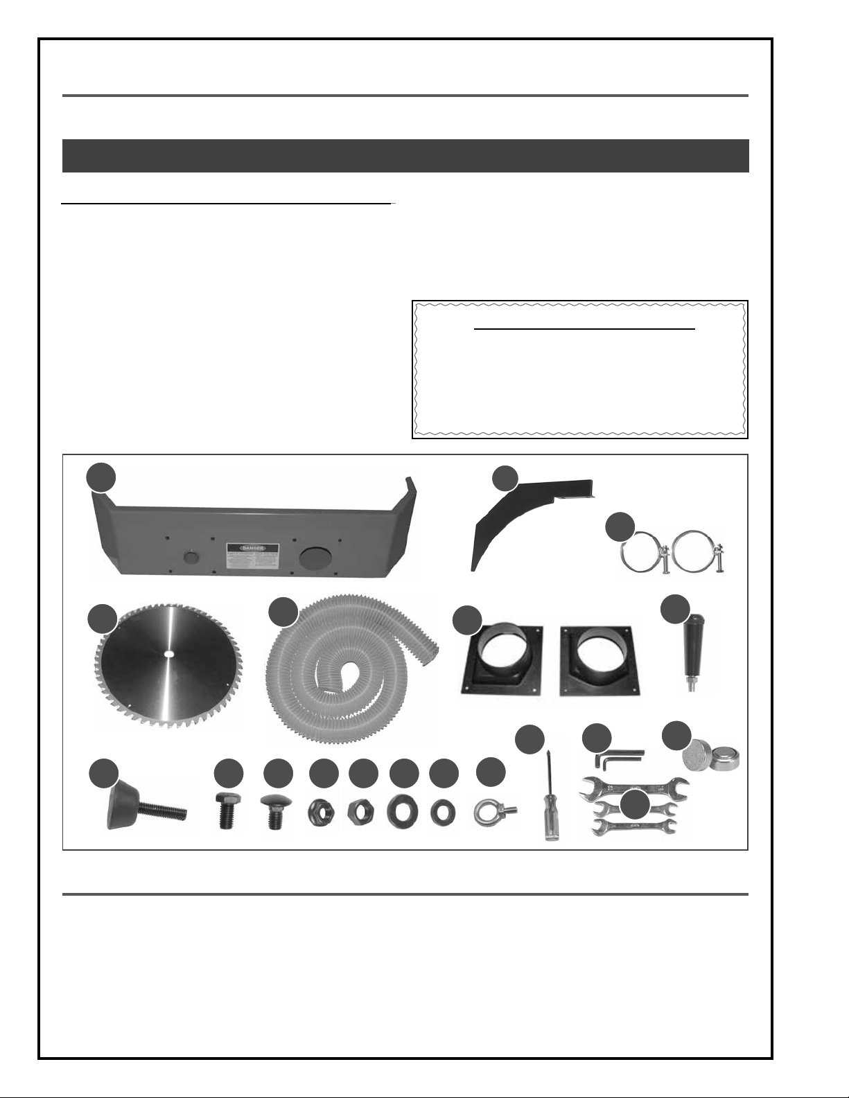
UNPACKING
Carefully unpack and remove the unit and its components from the box and check for missing or damaged items
as per the list of contents below.
NOTE: PLEASE REPORT ANY DAMAGED OR MISSING ITEMS TO YOUR GENERAL® INTERNATIONAL DISTRIBUTOR IMMEDIATELY.
LIST OF CONTENTS QTY
A. DUST PORT SUPPORT ................................................................ 1
B. RIVING KNIFE ........................................................................... 1
C. HOSE CLAMP ........................................................................... 2
D. BLADE ....................................................................................... 1
E. DUST HOSE ............................................................................... 1
F. DUST PORT ............................................................................... 2
G. HANDWHEEL KNOB ................................................................. 1
H. LEVELING FOOT ....................................................................... 4
I. BOLT ......................................................................................... 4
J. CARRIAGE BOLT ..................................................................... 16
K. FLANGE NUT ........................................................................... 16
L. NUT ........................................................................................... 4
M. WASHER (LARGER) .................................................................. 4
A
N. WASHER (SMALLER) ............................................................... 16
O. EYE HOOK ................................................................................ 2
P. REVERSIBLE FLAT/PHILLIPS SCREWDRIVER .............................. 1
Q. 5 & 8 MM ALLEN KEYS ............................................................. 1
R. 11-13, 12-14, 21-23 MM WRENCHES ....................................... 1
S. BUTTON CELL ........................................................................... 3
ADDITIONAL REQUIREMENTS FOR SET UP
A. 4 MM ALLEN KEY
B. 10 MM WRENCH
C. STRAIGHT EDGE
D. MACHINIST SQUARE
E. MEASURING CALIPERS
B
C
D
H
E
I J K L
M N
F
P Q
O
G
S
R
BASIC FUNCTIONS
This 12” radial arm saw is designed for multipurpose cutting of solid wood, as well as manufactured wood materials
and other wood based by-products. This saw is not designed for cutting metals nor for cutting any materials other
than wood or wood based stock.
This versatile unit offers a crosscutting capacity of 16” and uses maximum 12" (305 mm) diameter blades having
a center hole bore diameter of 5/8". The maximum stock thickness cutting capacity of this saw is 3” with the blade
set 90 degrees to the table. The blade can be tilted up to 45 degrees for bevel cuts to a maximum stock thickness
of 2". The 50-755 is also designed to perform miter cuts and compound (beveled) miters and has a dado cutting
capacity of 13/16”.
8
Page 9
PLACEMENT WITHIN THE SHOP / SAFETY ZONE
THIS RADIAL ARM SAW MODEL 50-755 IS HEAVY. DO NOT OVER-EXERT. A HOIST OR FORKLIFT WITH STRAPS SHOULD
BE USED TO LIFT THIS MACHINE. TO LIMIT THE RISK OF SERIOUS INJURY OR DAMAGE TO THE MACHINE, ANY EQUIPMENT USED TO LIFT THIS MACHINE SHOULD HAVE A RATED CAPACITY IN EXCESS OF 396 LBS (180 KG).
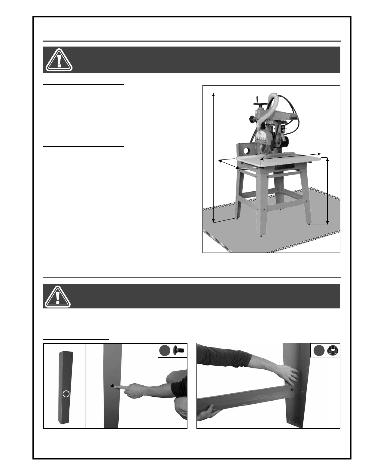
PLACEMENT WITHIN THE SHOP
This machine should be installed and operated only on a
solid, flat and stable floor that is able to support the weight
of the machine (396 lbs - 180 kg) and the operator. Using
the dimensions shown as a guideline, plan for placement
within your shop that will allow the operator to work unencumbered and unobstructed by foot traffic (either passing shop visitors or other shop workers) or other tools or
machinery.
ESTABLISHING A SAFETY ZONE
For shops with frequent visitors or multiple operators, it is
advisable to establish a safety zone around shop machinery. A clearly defined ”no-go” zone on the floor around
each machine can help avoid accidents that could
cause injury to either the operator or the shop visitor.
It is advisable to take a few moments to either paint (using
non-slip paint) or using tape, define on the floor the limits
or perimeter of each machines safety zone. Take steps to
ensure that all operators and shop visitors are aware that
these areas are off limits whenever a machine is running
for everyone but the individual operating the unit.
68"
35 1/4"
42"
37"
ASSEMBLY INSTRUCTIONS
BEFORE ASSEMBLING, MAKE SURE THAT THE SWITCH IS IN THE ”OFF” POSITION AND THAT THE POWER CORD IS
UNPLUGGED. DO NOT PLUG IN OR TURN ON THE MACHINE UNTIL YOU HAVE COMPLETED THE ASSEMBLY AND
INSTALLATION STEPS DESCRIBED IN THIS SECTION OF THE MANUAL.
Note: For your convenience this saw is shipped from the factory partially assembled and requires only minimal assembly
and set up before being put into service.
ASSEMBLING THE STAND
A B
1. Insert a carriage bolt A into the mounting hole as shown. 2. Secure a cross brace to the leg by hand tightening a
flange nut B.
9
Page 10
BEFORE ASSEMBLING, MAKE SURE THAT THE SWITCH IS IN THE ”OFF” POSITION AND THAT THE POWER CORD IS
UNPLUGGED. DO NOT PLUG IN OR TURN ON THE MACHINE UNTIL YOU HAVE COMPLETED THE ASSEMBLY AND
INSTALLATION STEPS DESCRIBED IN THIS SECTION OF THE MANUAL.
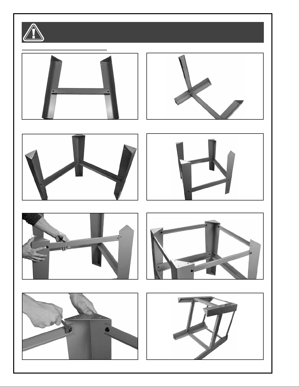
ASSEMBLING THE STAND (CONTINUED)
3. Secure another leg to the cross brace by hand tight-
ening a carriage bolt and a flange nut.
5. Repeat step 3 with another leg.
4. Repeat step 2.
6. Complete the assembly with the last leg and cross
braces.
7. Secure a small cross brace by hand tightening a
8. Repeat the step 7 with the 3 other cross braces.
carriage bolt and a flange bolt.
9. Tighten all the flange nuts using a 13 mm wrench. 10. Set the stand as shown on a flat surface.
10
Page 11
BEFORE ASSEMBLING, MAKE SURE THAT THE SWITCH IS IN THE ”OFF” POSITION AND THAT THE POWER CORD IS
UNPLUGGED. DO NOT PLUG IN OR TURN ON THE MACHINE UNTIL YOU HAVE COMPLETED THE ASSEMBLY AND
INSTALLATION STEPS DESCRIBED IN THIS SECTION OF THE MANUAL.
ASSEMBLING THE STAND (CONTINUED)
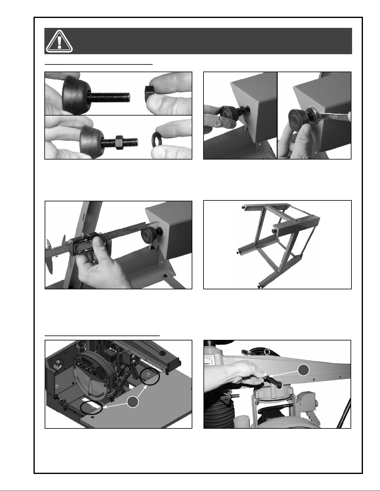
11. Tighten a nut to a leveling foot, then slide a flat
washer onto the rod.
13. Measure the distance from the leveling foot edge to
the end of the leg.
INSTALLING THE MACHINE ON THE STAND
12. Tighten the leveling foot under the leg, then lock
the leveling foot in place by tightening the jam nut
with a 11 mm wrench.
14. Repeat step 12 with the other leveling feet, install
ing them at the same distance measured in the
previous step.
A
1. Remove the 2 insert boards to access the lifting
hook mounting holes and then thread the 2 lifting
hooks A.
Note: The two other lifting hooks are already installed and
located on the dust port support.
B
2. Make sure the cutter head is lock in position by re-
tightening the lock lever B if needed.
11
Page 12
BEFORE ASSEMBLING, MAKE SURE THAT THE SWITCH IS IN THE ”OFF” POSITION AND THAT THE POWER CORD IS
UNPLUGGED. DO NOT PLUG IN OR TURN ON THE MACHINE UNTIL YOU HAVE COMPLETED THE ASSEMBLY AND
INSTALLATION STEPS DESCRIBED IN THIS SECTION OF THE MANUAL.
INSTALLING THE MACHINE ON THE STAND (CONTINUED)
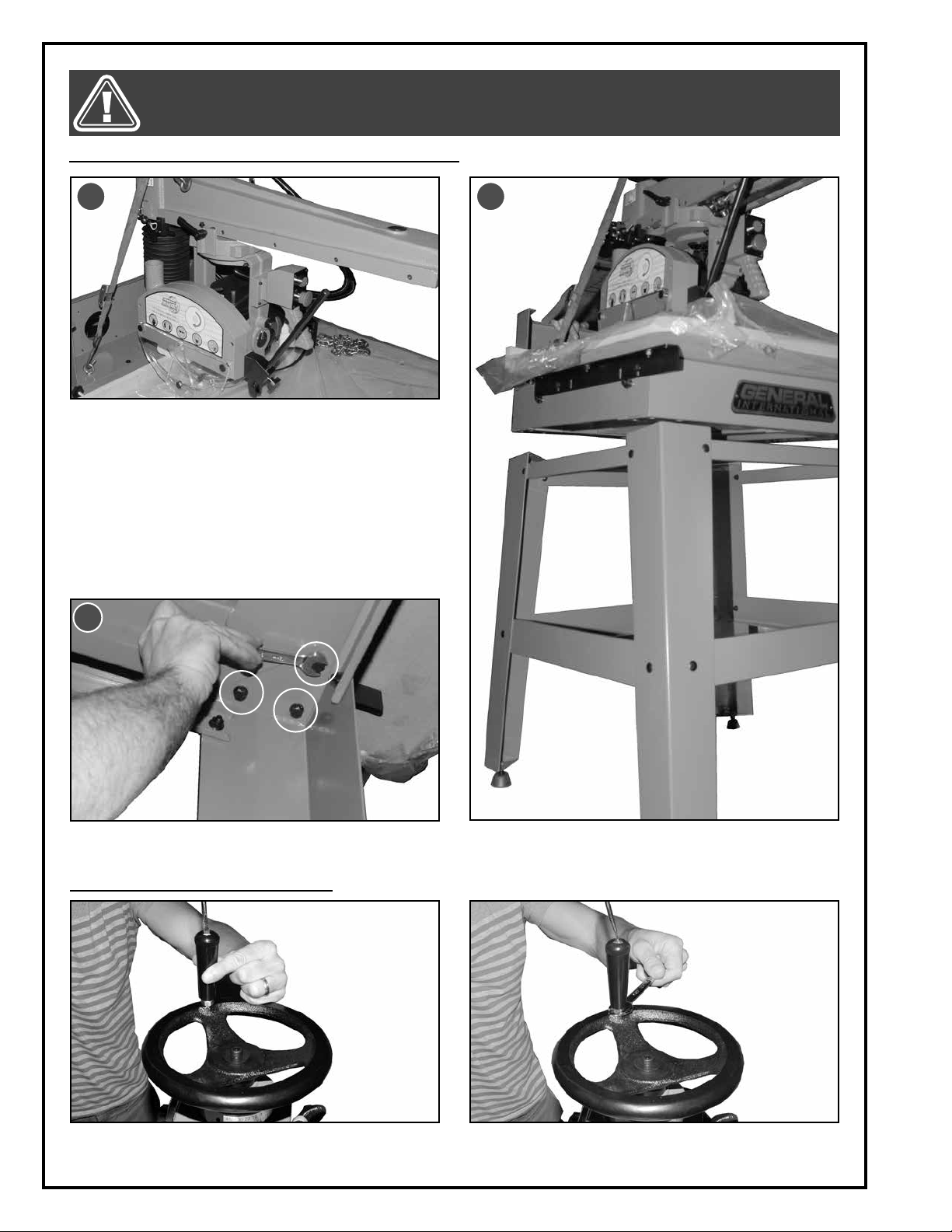
C
3. Slip appropriate lifting straps in the 4 lifting hooks C.
Note: Verify the load capacity of the straps.
4. Lift the machine head using an appropriate and
safety lifting equipment.
5. Hold the head above the stand and align the cut-
machine mounting holes with the corresponding
holes in the stand D.
6. Secure the machine to the stand from below using
three 12 mm nuts with washers at each corner of the
stand E.
E
D
INSTALLING THE HANDWHEEL HANDLE
1. Thread the handle into the handwheel using a
screwdriver.
12
2. Secure the handle by tightening the jam nut using
a 14 mm wrench.
Page 13
BEFORE ASSEMBLING, MAKE SURE THAT THE SWITCH IS IN THE ”OFF” POSITION AND THAT THE POWER CORD IS
UNPLUGGED. DO NOT PLUG IN OR TURN ON THE MACHINE UNTIL YOU HAVE COMPLETED THE ASSEMBLY AND
INSTALLATION STEPS DESCRIBED IN THIS SECTION OF THE MANUAL.
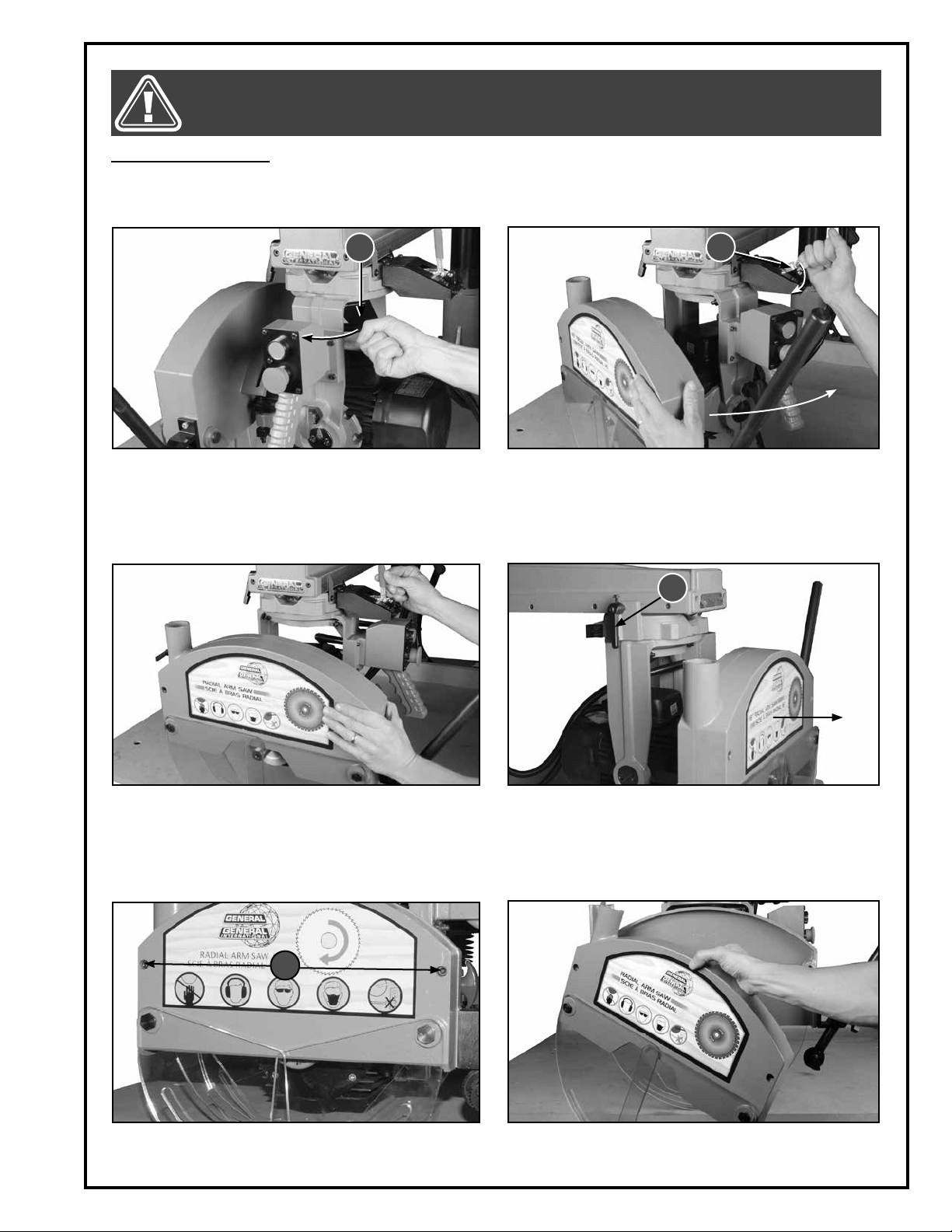
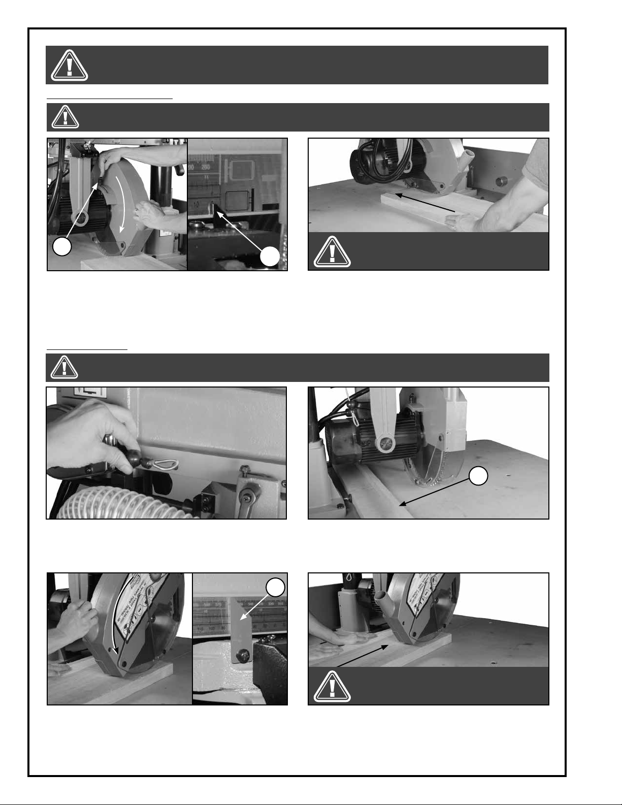
INSTALLING THE BLADE
There are a variety of different types of blades on the market to suit various cutting applications. Your results may
vary based on usage, experience and personal preference. Ask your local tool dealer for suggestions for 16” x 1”
(406 X 25 mm) blades.
A
1. Unlock the cutter head by turning the handle A to
the left.
B
2. While lowering handle B, rotate the cutter head the
right as shown.
C
3. Release handle B once the cutter head is posi-
tioned in front of you.
4. Loosen lock lever C to position the cutter head at
the end of the arm, then retighten the lever to lock
the cutter head in position.
D
5. Loosen the 2 screws D using a 6 mm Allen key. 6. Remove the blade cover.
13
Page 14

INSTALLING THE BLADE (CONTINUED)
7. Remove the arbor nut by turning it clockwise with a
19 mm wrench and by immobilising the arbor with
an 8 mm Allen key.
9. Install the blade onto the arbor.
8. Remove the laser.
Note: to install or replace the batteries see section "Installing the batteries in the laser".
Note: Before moving forward, make sure the blade teeth
are pointing to the right.
10. Re-install the laser and then the arbor nut. 11. Using an 8 mm Allen key to immobilise the arbor,
secure the blade by turning the arbor nut counterclockwise with a 23 mm wrench. Re-install the
blade cover before starting the machine.
INSTALLING THE BATTERIES IN THE LASER
1. Remove the two screws from the laser cover with a
Phillips screwdriver and detach the laser cover.
14
2. Slide a battery with the smooth side turned down into
one of the housings. Repeat with the other 2 batteries.
Note: The laser automatically turns on when the blade turns.
Page 15

BEFORE ASSEMBLING, MAKE SURE THAT THE SWITCH IS IN THE ”OFF” POSITION AND THAT THE POWER CORD IS
UNPLUGGED. DO NOT PLUG IN OR TURN ON THE MACHINE UNTIL YOU HAVE COMPLETED THE ASSEMBLY AND
INSTALLATION STEPS DESCRIBED IN THIS SECTION OF THE MANUAL.
INSTALLING THE ELECTRICAL BOX
1. Remove the 2 screws at the back of the machine
using a Phillips screwdriver.
INSTALLING THE DUST HOSE AND THE DUST PORTS
1. Slide the hose clamp onto the end of the dust hose.
2. Align the electrical box mounting holes with the
corresponding holes in the machine, then secure
the box to the stand using the two screws.
2. Slide the hose end onto the outlet, then secure it by
tightening the hose clamp with a Phillips screwdriver.
secure it in the vertical position by tightening the
cap screw with a 5 mm Allen key.
5. Secure the two dust ports to the support with the 8
screws.
4. Remove the 8 screws using a Phillips screwdriver.3. Slide the hose through the holder hose arm, then
6. Silde the hose end onto the blade cover outlet, then se-
cure the hose clamp using a Phillips screwdriver.
15
Page 16

BEFORE ASSEMBLING, MAKE SURE THAT THE SWITCH IS IN THE ”OFF” POSITION AND THAT THE POWER CORD IS
UNPLUGGED. DO NOT PLUG IN OR TURN ON THE MACHINE UNTIL YOU HAVE COMPLETED THE ASSEMBLY AND
INSTALLATION STEPS DESCRIBED IN THIS SECTION OF THE MANUAL.
INSTALLING THE RIVING KNIFE
A
1. Remove the two screws and washers located in
the blade cover using a 5 mm Allen key.
CONNECTING THE CUTTER HEAD TO THE RETURN SPRING
1. Position the cutter head close to the column and
pull on the return spring cable.
2. Secure the riving knife A to the blade cover with
the screws and washers.
2. Connect the cutter head by installing the cable as
shown.
Note: Disconnect the cutter head for ripping.
BASIC ADJUSTMENTS & CONTROLS
TO REDUCE THE RISK OF SHOCK OR FIRE DO NOT OPERATE THE UNIT WITH A DAMAGED POWER CORD OR PLUG. REPLACE DAMAGED CORD OR PLUG IMMEDIATELY. TO AVOID UNEXPECTED OR UNINTENTIONAL START-UP, MAKE SURE
THE POWER SWITCH IS IN THE OFF POSITION BEFORE CONNECTING TO A POWER SOURCE.
CONNECTING TO A POWER SOURCE
Once the assembly steps have been completed, plug
the power cord into an appropriate outlet.
Refer back to the section entitled ”Electrical Require
ments” and make sure all requirements and grounding
instructions are followed.
When cutting operations have been completed, un
plug the saw from the power source.
16
TO AVOID UNEXPECTED OR UNINTENTIONAL START-UP, MAKE
-
SWITCH OFF
-
SURE THAT THE POWER SWITCH
IS IN THE OFF POSITION BEFORE
CONNECTING TO A POWER
SOURCE.
Page 17

MAKE SURE THE MACHINE HAS BEEN TURNED OFF AND UNPLUGGED FROM THE POWER SOURCE BEFORE PERFORMING ANY MAINTENANCE OR ADJUSTMENTS.
MAIN ON/OFF MAGNETIC SWITCH
This machine is equipped with a magnetic safety
switch designed to protect the unit and the user from
power surges, power outages and unwanted or unintentional start-up.
The electrical box located in the back of the machine
is equipped with a safety lock-out switch with removable key. The machine can only be started by unlocking the button with the key and turning the button A to
the ON position.
Note: When the machine is not in use, remove the key and
store it in a safe place.
To start the saw, press the button B. To stop the saw,
press button C. Once button C has been pressed, the
machine can only be started by turning button C to
the right.
OVERLOAD PROTECTION
This machine is equipped with an overload protection feature. To prevent an electrical overload from damaging
the motor, in the event of a spike in line voltage or amperage draw, the internal electronic protection system will
automatically cut off power to the motor.
To reset the overload protection, proceed as follows:
A
B
C
D
1. Unplug the machine from the power source. Loos-
en the two screws D with a Phillips screwdriver and
then remove the electrical box cover.
ADJUSTING THE CUTTER HEAD HEIGHT
E
2. To reset the overload protection, press the button E.
Re-install the cover before re-starting the machine.
F
1. Loosen lock lever F.
2. Turn the handwheel to set the cutter head to the
desired height, then retighten the lock lever to lock
the cutter head in position.
17
Page 18

MAKE SURE THE MACHINE HAS BEEN TURNED OFF AND UNPLUGGED FROM THE POWER SOURCE BEFORE PERFORMING ANY MAINTENANCE OR ADJUSTMENTS.
POSITIONING OF THE CUTTER HEAD ON THE ARM
A
1. Loosen the lock lever A. 2. Place the cutter head on the radial arm as per the
desired position and retighten the lever A.
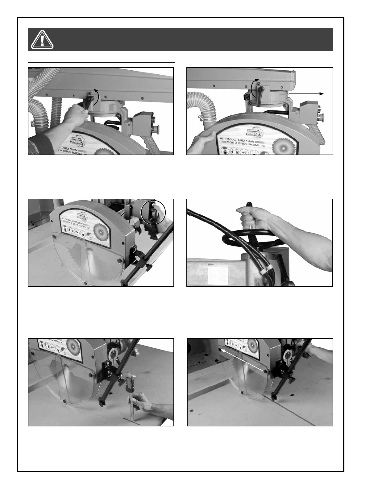
POSITIONING THE CUTTER HEAD FOR MITER CUTS
D
B
C
1. Loosen lock lever B, then unlock the arm by lifting
lock lever C.
PIVOTING THE CUTTER HEAD FOR RIPPING
E
2. Using the graduated scale D, position the arm to
the desired angle, then retighten lock lever B.
Note: To position the saw at 45º, lock the lever C into the
groove in the column.
F
1. Unplug the machine from the power source. Dis-
connect the cutter head from the return spring
and then unlock the cutter head by turning lever E to
the left.
18
2. While lowering lever F pivot the cutter head to the
right or to the left to the desired position. Lock the
cutter in position by tightening the lever E.
Note: Once it is released, the spring loaded lever F pin will
click into the ripping position.
Page 19
MAKE SURE THE MACHINE HAS BEEN TURNED OFF AND UNPLUGGED FROM THE POWER SOURCE BEFORE PERFORMING ANY MAINTENANCE OR ADJUSTMENTS.
PIVOTING THE CUTTER HEAD FOR BEVEL CROSS CUTTING
B
A
C
1. Unplug the machine from the power source. Dis-
connect the cutter head from the return spring.
Raise the cutter head. Loosen lock lever A, then
pull back the lock knob B.
2. Using the graduated scale C as a reference, pivot the
cutter head to one of the standard pre-set angles.
Note: Once it is released, the spring loaded lever B pin will
click into position.
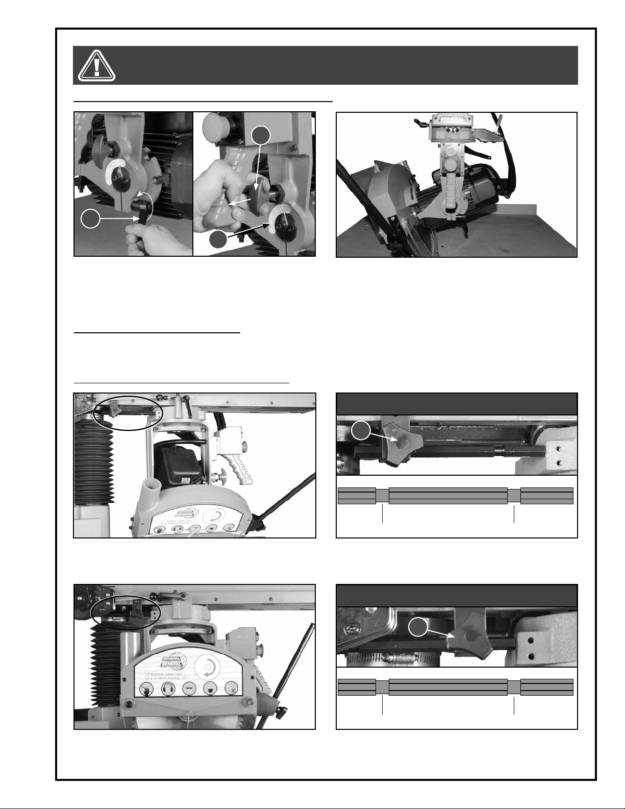
ADJUSTING THE CUTTER HEAD STOP
This saw is equipped with an adjustable workpiece stop to limit cutter head travel when dadoing or beveling to prevent the blade from touching the frame. To reduce the risk of damage and injury, it is imperative that this stop
is correctly adjusted according to the instructions in this manual and on the machine before using the saw.
The workpiece stop must be adjusted as follows:
CLOSED-UP
D
BEVELING CROSS CUTIING
When beveling, loosen the lock knob D and position
the stop in the dadoing position as shown. Retighten the
lock knob D.
When cross cutting, loosen lock knob D and position
the stop in the beveling position as shown. Retighten
the lock knob D.
CLOSED-UP
D
BEVELING CROSS CUTIING
19
Page 20

MAKE SURE THE MACHINE HAS BEEN TURNED OFF AND UNPLUGGED FROM THE POWER SOURCE BEFORE PERFORMING ANY MAINTENANCE OR ADJUSTMENTS.
ADJUSTING THE RETURN SPRING TENSION
A
B
To increase return spring tension, push up on lever A
while turning knob B counterclockwise.
ADJUSTING THE ANTI-KICKBACK FINGERS
TO PREVENT THE SAW “KERF” FROM CLOSING AND BINDING THE BLADE, WHICH CAN OVERLOAD AND/OR STALL
THE MOTOR OR CAUSE THE BLADE TO LIFT AND EJECT THE WORKPIECE TOWARDS THE FRONT OF THE SAW AT VERY
HIGH SPEEDS, ALWAYS USE THE ANTI-KICKBACK FINGERS AND SPLITTER/RIVING DISC.
1. Start ripping the workpiece until the saw kerf reach-
es the anti-kickback fingers, then stop the machine
and wait for the blade to come to a complete stop.
To decrease tension, push up lever B while turning A
clockwise.
D
C
2. Loosen knob C and place the riving disc D inside
the saw kerf making sure that the fingers rest on the
workpiece. Retighten knob C and continue sawing the workpiece.
POSITIONING THE FENCE
H
G
F
E
1. To reposition the fence E on the table, loosen the
clamps F and re-install the fence on G or H as
needed. Retighten the two clamps.
20
Note: To reduce muscle fatigue during repetitive cross cuttings, install the fence closer to the front edge of the table
as shown.
Page 21

CONNECTING TO A DUST COLLECTOR
ALWAYS TURN ON THE DUST COLLECTOR BEFORE STARTING THE SAW AND ALWAYS STOP THE SAW BEFORE TURNING OFF
THE DUST COLLECTOR.
Dual 4” dust ports are provided to accommodate connection to a dust collector (not included).
Be sure to use appropriate sized hose and fittings (not
included). Check that all connections are sealed tightly to help minimize airborne dust.
If you do not already own a dust collection system
consider contacting your General® International distributor for information on our complete line of dust
collection systems and accessories or visit our Web
Site at www.general.ca.
OPERATING INSTRUCTIONS
CHECKLIST BEFORE STARTING
VERIFY ALL CHECK POINTS BEFORE STARTING. FAILURE TO COMPLY CAN RESULT IN SERIOUS INJURIES.
1. Make sure you and any assistants are wearing safe and appropriate workshop attire.
2. To reduce the risk of damage to the machine, as well as potential for personal injury, after initial set-up as well
as before each use, make sure that everything is securely installed and that all fasteners and moving parts on
this machine are locked in place before starting the machine.
3. Make sure to have on safety glasses as well as hearing or/and respiratory protection at all times when using the
machine.
4. Use only recommended parts and accessories. The use of parts or accessories NOT recommended by
GENERAL® INTERNATIONAL may result in a risk of injury or damage to the machine.
5.
Be sure that adjusting wrenches, tools, drinks and other clutter are removed from the machine and/or the
table surface before operating.
CUTTING THE KERF IN THE WORK TABLE
This saw comes with both a sacrificial work table and fence. Before putting the machine into service, a partial kerf
cut of approx 1/16" deep is needed in the fence and the table.
To cut the kerf proceed as follows:
1. Loosen the two fence clamps located on the back
of the table.
2. Install the fence in the position furthest from the
column as shown, then tighten the fence clamps
to secure everything in place..
21
Page 22
MAKE SURE THE MACHINE HAS BEEN TURNED OFF AND UNPLUGGED FROM THE POWER SOURCE BEFORE PERFORMING ANY MAINTENANCE OR ADJUSTMENTS.
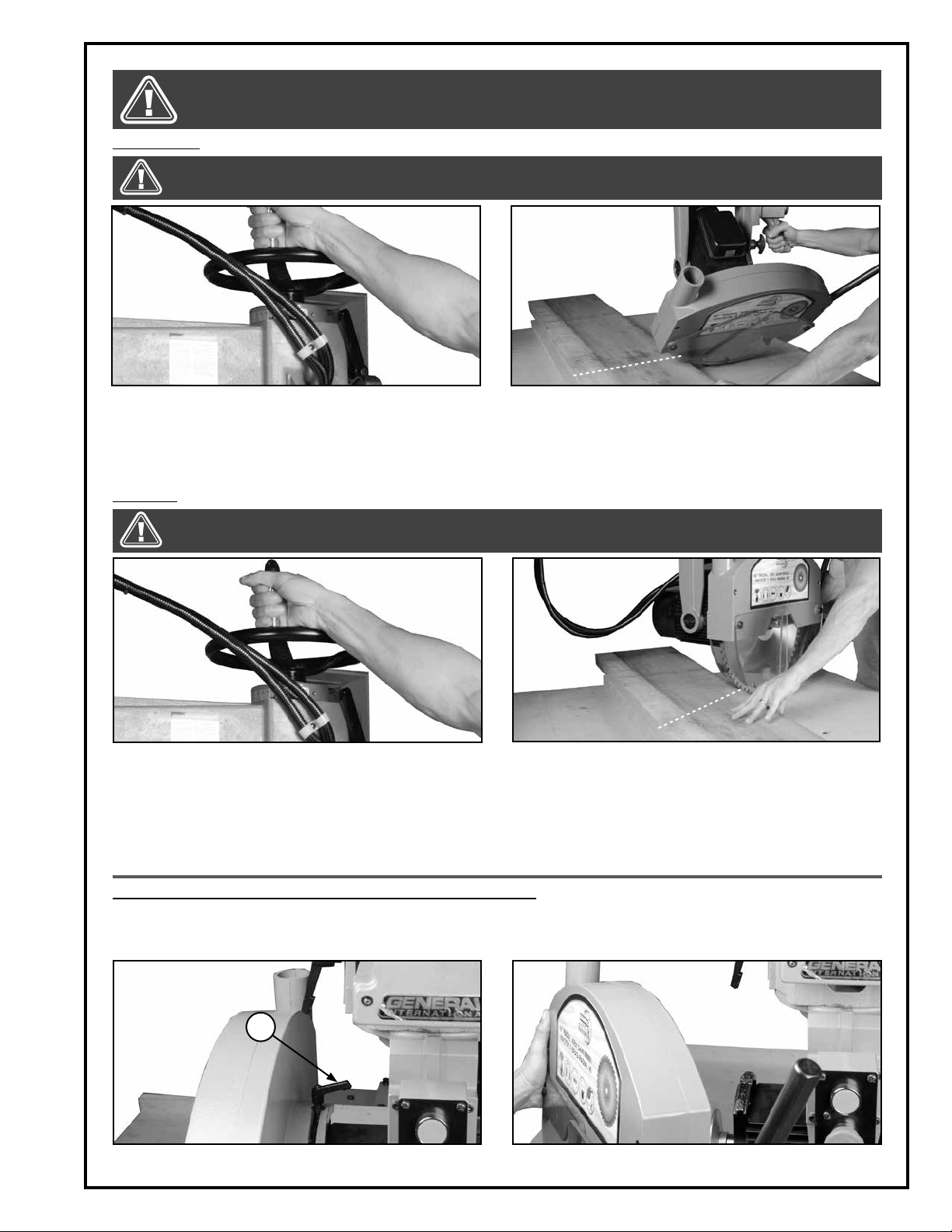
CUTTING THE KERF IN THE WORK TABLE (CONTINUED)
3. Loosen the cutter head lock lever. 4. Position the cutter head at the end of the arm, then
retighten the lever to lock the cutter head in position.
5. Turn the saw on. 6. Unlock the arm (see section ”Adjusting the cutter
head height”), then slowly lower the cutter head to
perform A 1/16” depth cut in the work table.
7. Turn the saw off by pressing the stop button, then
wait for the blade to stop. Measure the depth of the
kerf. If needed, repeat the previous step until the
required depth is reached. Do not adjust the cutter
8. Turn the saw on then push the cutter head forward
to cut the kerf in the table and the fence.
Note: The user also needs to make kerf cuts for beveling,
miters, inboard ripping and outboard ripping.
head height any further.
22
Page 23
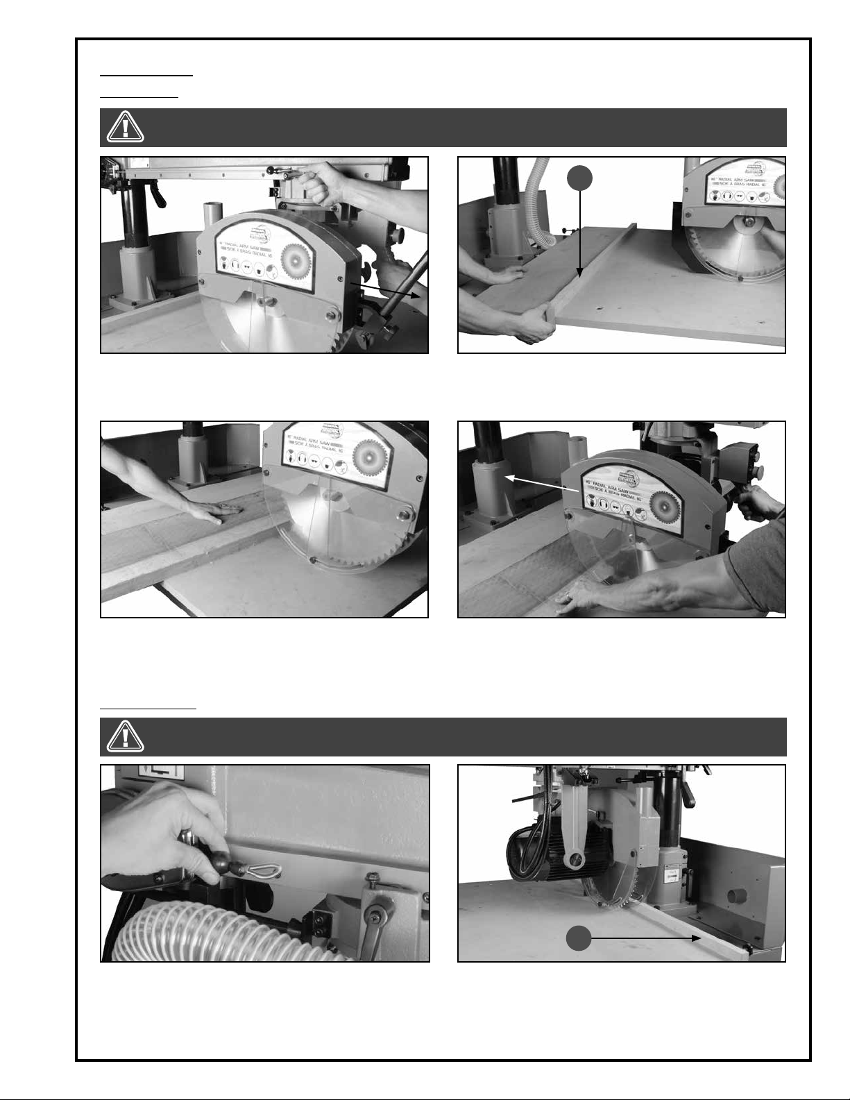
TYPES OF CUTS
Cross cutting
NEVER USE THE SAW WITHOUT ALL GUARDS AND COVERS IN PLACE. BEFORE STARTING THE SAW BE SURE THAT THE
BLADE IS NOT ALREADY IN CONTACT WITH THE WORKPIECE.
A
1. Unlock the cutter head and position it at the end of
the arm. Retighten the lever to lock the cutter head
in position.
3. Place the workpiece on the table and align the
cut line with the blade.
Inboard ripping
NEVER USE THE SAW WITHOUT ALL GUARDS AND COVERS IN PLACE. BEFORE STARTING THE SAW BE SURE THAT THE
BLADE IS NOT ALREADY IN CONTACT WITH THE WORKPIECE.
2. Install the fence A as shown and lock it by retight-
ening its two clamps (see section ”Positioning the
fence” if needed).
4. Unlock the cutter head, and then while holding
handle firmly, turn the saw on and push the blade
forward. Once the workpiece is cut, turn the saw off
and wait for the blade to come to a complete stop
before removing the workpiece.
A
1. Discnnect the return cable from the cutter head. 2. Pivot the cutter head as shown, with the blade turned
to the column side (see section ”Pivoting the cutter
head”).
Note: For inboard ripping, the fence A has to be installed
at the end of the work table.
23
Page 24
MAKE SURE THE MACHINE HAS BEEN TURNED OFF AND UNPLUGGED FROM THE POWER SOURCE BEFORE PERFORMING ANY MAINTENANCE OR ADJUSTMENTS.
Inboard ripping (continued)
NEVER USE THE SAW WITHOUT ALL GUARDS AND COVERS IN PLACE. BEFORE STARTING THE SAW BE SURE THAT THE
BLADE IS NOT ALREADY IN CONTACT WITH THE WORKPIECE.
B
A
3. Place the workpiece on the table. Refer to the
graduated scale and pointer A, to position the cutter head with the blade aligned with the cut line.
Loosen the lock lever B to lower the blade guard
so that it almost touches the workpiece, and then
retighten the lock lever.
4. Turn the saw on and push the workpiece forward.
Adjust the anti-kickback fingers (see section ”Adjusting the anti-kickback fingers”). Once the workpiece is cut, turn the saw off and wait for the blade
to come to a complete stop before removing the
workpiece.
IF THE WORKPIECE TO BE RIPPED IS NARROW,
IT IS SAFER TO USE A PUSH STICK, RATHER
THAN HANDS, TO FEED IT INTO THE BLADE.
Outboard Ripping
NEVER USE THE SAW WITHOUT ALL GUARDS AND COVERS IN PLACE. BEFORE STARTING THE SAW BE SURE THAT THE
BLADE IS NOT ALREADY IN CONTACT WITH THE WORKPIECE.
C
1. Disconnect the cable from the cutter head. 2. Pivot the cutter head as shown, with the blade op-
posite to the column side (see section ”Pivoting
the cutter head”).
Note: The fence C has to be installed as shown.
3. Place the workpiece on the table. Refer to the
graduated scale and pointer C to position the cutter head with the blade aligned with the cut line.
Then lower the blade guard so that it almost touches the workpiece and retighten the lock lever.
24
C
IF THE WORKPIECE TO BE RIPPED IS NARROW,
IT IS SAFER TO USE A PUSH STICK, RATHER
THAN HANDS, TO FEED IT INTO THE BLADE.
4. Turn the saw on and push the workpiece forward.
Adjust the anti-kickback fingers (see section ”Adjusting the anti-kickback fingers”). Once the workpiece
is cut, turn the saw off and wait for the blade to come
to a complete stop before removing the workpiece.
Page 25
Bevel cutting
NEVER USE THE SAW WITHOUT ALL GUARDS AND COVERS IN PLACE. BEFORE STARTING THE SAW BE SURE THAT THE
BLADE IS NOT ALREADY IN CONTACT WITH THE WORKPIECE.
WHENEVER A RIP CUT IS COMPLETED, TURN OFF THE SAW AND WAIT FOR THE BLADE TO COME TO A COMPLETE STOP
BEFORE REACHING IN TO REMOVE THE WORKPIECE OR THE WASTE MATERIAL.
1. If necessary raise the cutter head enough for the
blade to be slightly above the table to tilt freely,
then disconnect the cutter head from the return
spring.
Miter cuts
NEVER USE THE SAW WITHOUT ALL GUARDS AND COVERS IN PLACE. BEFORE STARTING THE SAW BE SURE THAT THE
BLADE IS NOT ALREADY IN CONTACT WITH THE WORKPIECE.
1. If necessary raise the cutter head enough for the
blade to be slightly above the table to pivot freely,
then disconnect the cutter head from the return
spring.
2. Place the workpiece on the table, then tilt the cutter
head to the desired angle (see section ”Tilting the
cutter head). Turn the saw on and push the blade
forward. Once the workpiece is cut, turn the saw off
and wait for the blade to come to a complete stop
before removing the workpiece.
2. Place the workpiece on the table, then position the cut-
ter head to the desired angle (see section ”Adjusting
the blade for miter cuts”). Turn the saw on and push the
blade forward. Once the workpiece is cut, turn the saw
off and wait for the blade to come to a complete stop
before removing the workpiece.
MAINTENANCE
ADJUSTING THE WORK TABLE PARALLEL TO THE CUTTER HEAD
The work table has been pre-set parallel to the table at the factory, therefore, except in some rare cases (important maintenance, improper handling or rough transport) no further adjustments are required. If an ajustment is
required, proceed as follows:
A
1. Remove the lever A with its washer. 2. Remove the blade then remove the blade cover.
25
Page 26

MAKE SURE THE MACHINE HAS BEEN TURNED OFF AND UNPLUGGED FROM THE POWER SOURCE BEFORE PERFORMING ANY MAINTENANCE OR ADJUSTMENTS.
ADJUSTING THE WORK TABLE PARALLEL TO THE CUTTER HEAD (CONTINUED)
B
C
3. Unlock the cutter head by loosening the lever B.
4. Pivot the cutter head into the vertical position, then
release knob C so that the positive stop pin locks
the cutter head in the vertical position.
4. Pull back on knob C.
5. Position the cutter head in the centre of the work
table. Place a shop-made reference block underneath the cutter head.
Note: Your reference block can be made of wood with 2
machined faces perfectly parallel to each other.
6. Lower the cutter head until it just slightly touches the
adjustment block. Do not modify the cutter head
height any further until the adjustment is done.
26
7. Slide the cutter head to the end of the arm, then
place the block underneath. If the cutter head
does not slighty touch the block as in the previous
step, go to the next step. If the cutter head does just
slightly touch the block, go to the step 10.
Page 27

MAKE SURE THE MACHINE HAS BEEN TURNED OFF AND UNPLUGGED FROM THE POWER SOURCE BEFORE PERFORMING ANY MAINTENANCE OR ADJUSTMENTS.
ADJUSTING THE WORK TABLE PARALLEL TO THE CUTTER HEAD (CONTINUED)
D
F
C
9. Loosen the bolts C located on both sides of the ta-
ble with a 13 mm wrench and re-adjust the low end
of the table by turning the excentric ring located
behind each bolt D in the required direction until
the block just slight touches the cutter head. Retighten the bolt C & D.
SQUARING THE BLADE TO THE TABLE
The blade has been pre-set square (90°) to the table at the factory, therefore, except in some rare cases (important maintenance, improper handling or rough transport) no further adjustments are required. If an ajustment is
require, proceed as follows:
10. Repeat the previous step with the head at the opposite end of arm with bolts E & F as needed.
E
1. Remove the dust hose from the blade cover. 2. Remove the blade cover using a 5 mm Allen key.
A
C
B
3. Place the cutter head at the end of the arm, and
then lock it in place by retightening the lever A.
4. Make sure that the knob B is fully forward and lever
C is tightened.
27
Page 28

MAKE SURE THE MACHINE HAS BEEN TURNED OFF AND UNPLUGGED FROM THE POWER SOURCE BEFORE PERFORMING ANY MAINTENANCE OR ADJUSTMENTS.
SQUARING THE BLADE TO THE TABLE (CONTINUED)
D
5. Place a square against the blade. If an ajustment
is required, then go to the next step.
F
E
7. Loosen the two nuts E using a 12 mm wrench, then
adjust the blade squareness to the table by turning the set screws F with a 4 mm Allen key. Once
the adjustment is done, retighten bolts E.
6. Unlock the blade cover by loosening lever D then
pivot the blade cover to the rear. Retighten lever D
to secure the blade cover in position.
8. Loosen the pointer using a Phillips screwdriver, then
reposition the pointer to ”0”. Retighten the pointer.
SQUARING THE BLADE TO THE FENCE
1. Loosen the riving knife using a 5 mm Allen key,
then remove the riving knife.
28
2. Raise the lower blade cover.
Page 29

MAKE SURE THE MACHINE HAS BEEN TURNED OFF AND UNPLUGGED FROM THE POWER SOURCE BEFORE PERFORMING ANY MAINTENANCE OR ADJUSTMENTS.
SQUARING THE BLADE TO THE FENCE (CONTINUED)
90°
3. Place a square on the work table.
Note: The fence must be installed at the end of the table.
5. Pull the cutter head to the end of the arm to verify
4. Then place a straight edge against the square
6. Loosen nut A with a 12 mm wrench, then turn the
that the blade tracks parallel to the straight edge.
If the blade is not parallel, then go to the next step.
ADJUSTING THE GRADUATED SCALE FOR INBOARD RIPPING
and against the blade.
A
B
2 set screws B with a 4 mm Allen key as needed to
adjust the blade square to the fence.
CLOSE-UP
1. Raise the lower blade covers. Position the blade flush
against the fence, then lock the cutter head in position.
Note: The fence must be installed at the end of the table.
C
2. Verify that the pointer C indicates ”0”. If not, loosen
the pointer with a Phillips screwdriver then re-align
the pointer with ”0”. Retighten the pointer.
29
Page 30

MAKE SURE THE MACHINE HAS BEEN TURNED OFF AND UNPLUGGED FROM THE POWER SOURCE BEFORE PERFORMING ANY MAINTENANCE OR ADJUSTMENTS.
CUTTER HEAD BEARING ADJUSTMENT
The cutter head bearings have been adjusted at the factory, therefore, except in some rare cases (important mainte-
nance, improper handling or rough transport) no further adjustments are required. With use over time, some slight play
may develop in head on the rails due to wear. To eliminate play between the head and the rails, proceed as follows:
PROCEED WITH CAUTION – TO REDUCE THE RISK OF CUTTER HEAD SLIDING OFF THE END OF THE ARM AND FALLING, CAUSING DAMAGE TO THE HEAD AND/OR INJURY TO THE USER, MAKE SURE TO RE-INSTALL THE ARM’S FRONT
COVER BEFORE UNLOCKING THE CUTTER HEAD.
B
A
B
1. Disconnect the cutter head from the return spring,
then lock the cutter head at the end of the arm by
retightening the lever A. Remove the arm cover B
using a 5 mm Allen key.
D
E
E
D
2. Loosen bolt B with a 19 mm wrench and loosen jam
C
nut C with an 10 mm wrench.
F
3. Turn the bolt F in the required direction until the 2
bearing E are leaning against the rails D. Re-install
the arm cover before unlocking the cutter head to
make a test by moving the cutter.
Note: Adjust only enough to eliminate play – do not over tighten as this can stiffen or restrict head travel, requiring more
effort to move it and cause premature wear of the rails.
ADJUSTING THE BASE
The base bas been adjusted at the factory, therefore, except in some rare cases (important maintenance, improper
handling or rough transport) no further adjustments are required. If the clamp tension of the base makes the cutter
height adjustment harder or if you notice some play between the column and base, proceed as follows:
4. Repeat steps 2 & 3 with the other bearing assembly
located in the back of the cutter head.
A
1. Unlock the column by loosening the lever A.
30
C
B
2. Loosen the jam nuts B using a 12 mm wrench, then
loosen without removing the 2 set screws C.
Page 31

ADJUSTING THE BASE (CONTINUED)
B
C
4. Loosen the 2 bolts C using a 13 mm wrench to re-
duce clamping tension on the column for smoother cutter head height adjustments.
6. Retighten the jam nuts once the adjustment is
done.
ADJUSTING THE CUTTER HEAD ARM
If you notice play between the arm and column, proceed as follows:
5. Loosen the 2 bolts C using a 13 mm wrench to re-
duce clamping tension on the column for smoother cutter head height adjustments
Note: Tighten bolts only enough to eliminate play. Over
tightening can stiffen head travel.
7. Loosen the 2 bolts C using a 13 mm wrench to re-
duce clamping tension on the column for smoother cutter head height adjustments.
Note: Tighten bolts only enough to eliminate play. Over
tightening can stiffen head travel.
A
B
A
1. Loosen the 2 jam nuts A using a 14 mm wrench. 2. Unlock the arm by loosening the lever B.
C
C
3. Retighten the nuts C using a 17 mm wrench to
eliminate the play between the arm and column.
4. Retighten lever B and verify that the play between
the arm and column has been eliminated. Then
retighten the 2 jam nuts.
31
Page 32

DIAGRAM A
TABLE AND STAND - 50-755
32
Page 33

PARTS LIST A
TABLE AND STAND - 50-755
IMPORTANT: When ordering replacement parts, always give the model number, serial number of the
machine and part number. Also a brief description of each item and quantity desired.
# PART NO. REF. NO. DESCRIPTION SPECIFICATIONS QTY
1 50755-A01 71011009 INSERT BOARD 2
3 50755-A03 71011007 INSERT BOARD (WIDE) 1
4 50755-A04 71011006 MAIN TABLE 1
5 50755-A05 50102013 CAP SCREW M8 X 1.25P X 30L 4
6 50755-A06 50301102 FLAT WASHER 8.2 X 16 X 1T 32
7 50755-A07 50101064 HEX. BOLT M8 X 1.25P X 16L 18
8 50755-A08 71011015 CAM BUSHING 4
9 50755-A09 71011011 STOP 2
10 50755-A10 71011010 STOP HOLDER 2
11 50755-A11 50201019 HEX NUT M8 X 1.25P 11
12 50755-A12 14031009 LOCK KNOB M8 X 1.25P X 80L 2
13 50755-A13 50102018 CAP SCREW M8 X 1.25P X 12L 2
14 50755-A14 71011005 TABLE REST BAR 2
15 50755-A15 50103024 SET SCREW M8 X 1.25P X 25L 5
16 50755-A16 71011004 BASE FRAME 1
17 50755-A17 71011013 DUST PORT SUPPORT 1
18 50755-A18 71011012 DUST HOSE 1
19 50755-A19 71011016 HOSE CLAMP 1
20* 50755-A20A 71011651 M1 MAGNETIC SWITCH ASS’Y M1 - 2HP, 220/240V, 1PH 1
20* 50755-A20B 71011652 M2 MAGNETIC SWITCH ASS’Y M2 - 3HP, 220/240V, 3PH 1
20.1* 50755-A20.1A 71011601 M1 MAGNETIC SWITCH ONLY M1 - 2HP, 220/240V, 1PH 1
20.1* 50755-A20.1B 71011602 M2 MAGNETIC SWITCH ONLY M2 - 3HP, 220/240V, 3PH 1
20.2 50755-A20.2 51104010 STRAIN RELIEF N-MGN20-15B-ST M20 X 1.5P 2
20.3 50755-A20.3 51106004 CORD COIL NGN-12B 3/8”X 225CM 1
20.4* 50755-A20.4A 71011701 M1 MOTOR CORD SJT 14AWG X 3C X 250CM 1
20.4* 50755-A20.4B 71011702 M2 MOTOR CORD SJT 14AWG X 4C X 250CM 1
20.5 50755-A20.5 71011901 SWITCH CORD SJT 18AWG X 3C X 270CM 1
20.6 50755-A20.6 51106005 CORD COIL NGN-12B 3/8” X 238CM 1
20.7* 50755-A20.7A 71011801 M1 POWER CORD SJT 14AWG X 3C X 230CM+CSA 1
20.7* 50755-A20.7B 71011802 M2 POWER CORD SJT 14AWG X 4C X 230CM 1
20.8 50755-A20.8 51104008 STRAIN RELIEF PG 13.5 1
20.9 50755-A20.9 50104049 SCREW M4 X 0.7P X 12L 2
20.10 50755-A20.10 71011014 SWITCH PLATE 1
21 50755-A21 34011020 DUST PORT 2
22 50755-A22 71011001 STAND LEG 4
23 50755-A23 50160012 CARRIAGE BOLT 5/16”- 18 UNC X 5/8”L 16
24 50755-A24 71011002 LOWER TIE BAR 4
25 50755-A25 50256002 HEX NUT 5/16”- 18 UNC 16
26 50755-A26 50251023 HEX NUT 3/8”- 16 UNC 8
27 50755-A27 50301085 FLAT WASHER 10 X 20 X 2.0T 8
28 50755-A28 24051007 LEVELING FOOT 4
29 50755-A29 50101034 HEX BOLT M8 X 1.25P X 25L 4
30 50755-A30 71011003 UPPER TIE BAR 4
31 50755-A31 50104014 SCREW M5 X 0.8P X 10L 10
32 50755-A32 50125001 EYE BOLT M8 X 1.25P X 15L 2
33 50755-A33 50301107 FLAT WASHER 5 X 12 X 1T 8
34 50755-A34 50301014 FLAT WASHER 8.5 X 20 X 3T 4
* Check voltage/electrical specifications before ordering.
33
Page 34

DIAGRAM B
COLUMN - 50-755
IMPORTANT: When ordering replacement parts, always give the model number, serial number of the
machine and part number. Also a brief description of each item and quantity desired.
# PART NO. REF. NO. DESCRIPTION SPECIFICATIONS QTY
1 50755-B01 50102010 CAP SCREW M8 X 1.25P X 16L 3
2 50755-B02 50301084 FLAT WASHER 8 X 30 X 3T 3
3 50755-B03 71012006 HANDWHEEL 1
4 50755-B04 50503003 BEARING 51102 2
5 50755-B05 50103041 SET SCREW M6 X 1.0P X 6L 3
6 50755-B06 71012005 UPPER COVER 1
7 50755-B07 71012010 COLUMN 1
8 50755-B08 34013101 HANDLE ASS’Y 1
8.1 50755-B08.1 34013024 SCREW 1
8.2 50755-B08.2 34013021 HANDLE 1
8.3 50755-B08.3 50251006 HEX. NUT 3/8”- 16 UNC 1
9 50755-B09 50102017 CAP SCREW M5 X 0.8P X 12L 7
10 50755-B10 71012004 GUIDE BEAM 1
11 50755-B11 50604005 KEY 5 X 5 X 12L 2
12 50755-B12 71012009 CLIP 1
13 50755-B13 71012007 RUBBER COIL 1
14 50755-A33 50301107 FLAT WASHER 5 X 12 X 1T 4
15 50755-B15 50104044 SCREW M5 X 0.8P X 6L 4
16 50755-B16 71012011 LOCATION SLEEVE 1
17 50755-B17 71012001 LEAD SCREW 1
18 50755-B18 71012002 COLUMN BASE 1
19 50755-B19 50101041 HEX. BOLT M12 X 1.75P X 55L 4
20 50755-B20 50302009 LOCK WASHER M12 4
21 50755-B21 50301075 FLAT WASHER 12 X 23 X 2T 5
22 50755-B22 71012003 LEAD SCREW HOLDER 1
23 50755-A27 50301085 FLAT WASHER 10 X 20 X 2.0T 2
24 50755-B24 50302010 LOCK WASHER M10 2
25 50755-B25 50101050 HEX BOLT M10 X 1.5P X 30L 2
26 50755-A11 50201019 HEX NUT M8 X 1.25P 4
27 50755-A06 50301102 FLAT WASHER 8.2 X16 X 1T 4
28 50755-B28 71012008 POSITIONAL SCREW 2
29 50755-B29 50101039 HEX BOLT M8 X 1.25P X 55L 2
30 50755-B30 50114041 LOCKING LEVER M12 X 1.75P X 60L 1
31 50755-B31 501011046 HEX. BOLT 1
32 50755-B32 50201019 HEX. NUT 1
34
Page 35
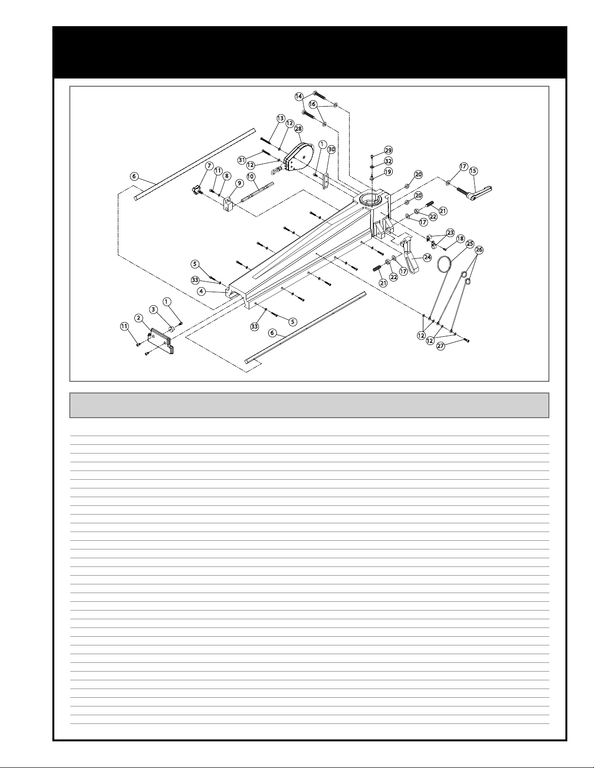
DIAGRAM C
RADIAL ARM - 50-755
14
16
13
12
28
1
30
31
7
6
1
3
2
11
11
5
33
4
12
8
10
9
33
5
6
29
32
19
21
20
20
22
17
24
17
22
12
12
17
15
21
23
18
25
26
27
IMPORTANT: When ordering replacement parts, always give the model number, serial number of the
machine and part number. Also a brief description of each item and quantity desired.
# PART NO. REF. NO. DESCRIPTION SPECIFICATIONS QTY
1 50755-C01 50102023 CAP SCREW M6 X 1.0P X 10L 4
2 50755-C02 71013002 ARM COVER 1
3 50755-C03 71013003 FRONT SUSPENSION 1
4 50755-C04 71013001 ARM 1
5 50755-C05 50102021 CAP SCREW M5 X 0.8P X 25L 10
6 50755-C06 71013005 RAIL BEAM 2
7 50755-C07 50164003 LOCK KNOB M8 X 1.25P X 19L 1
8 50755-C08 50302007 LOCK WASHER M6 1
9 50755-C09 71013011 DEPTH BAR HOLDER 1
10 50755-C10 71013012 DEPTH BAR 1
11 50755-C11 50102006 CAP SCREW M6 X 1.0P X 16L 1
12 50755-C12 50301087 FLAT WASHER 6 X 12 X 1T 6
13 50755-C13 50104063 SCREW M6 X 1.0P X 50L 1
14 50755-C14 50101038 HEX. BOLT M10 X 1.5P X 55L 2
15 50755-B30 50114041 LOCKING LEVER M12 X 1.75P X 60L 1
16 50755-A27 50301085 FLAT WASHER 10 X 20 X 2.0T 2
17 50755-B21 50301075 FLAT WASHER 12 X 23 X 2T 3
18 50755-A31 50104014 SCREW M5 X 0.8P X 10L 1
19 50755-C19 35011016 POINTER 1
20 50755-C20 50201016 HEX. NUT M10 X 1.5P 2
21 50755-C21 71013009 POSITION LOCK SCREW 2
22 50755-C22 50201022 HEX. NUT M12 X 1.75P 2
23 50755-C23 51110007 CABLE CLIP ACC-5 (15MM) 2
24 50755-C24 71013004 POSITIONING HANDLE 1
25 50755-C25 71013006 COIL PIPE SUPPORT, LARGE 1
26 50755-C26 71013010 COIL PIPE SUPPORT, SMALL 2
27 50755-C27 50102007 CAP SCREW M6 X 1.0P X 20L 1
28 50755-C28 71013008 RETURN COIL 1
29 50755-C29 50104018 SCREW M4 X 0.7P X 8L 1
30 50755-C30 71013007 RETURN COIL MOUNT 1
31 50755-C31 50104069 SCREW M6 X 1.0P X 35L 1
32 50755-C32 50301078 FLAT WASHER 4.2 X 8 X 0.8T 1
33 50755-C33 50302006 LOCK WASHER M5 10
35
Page 36
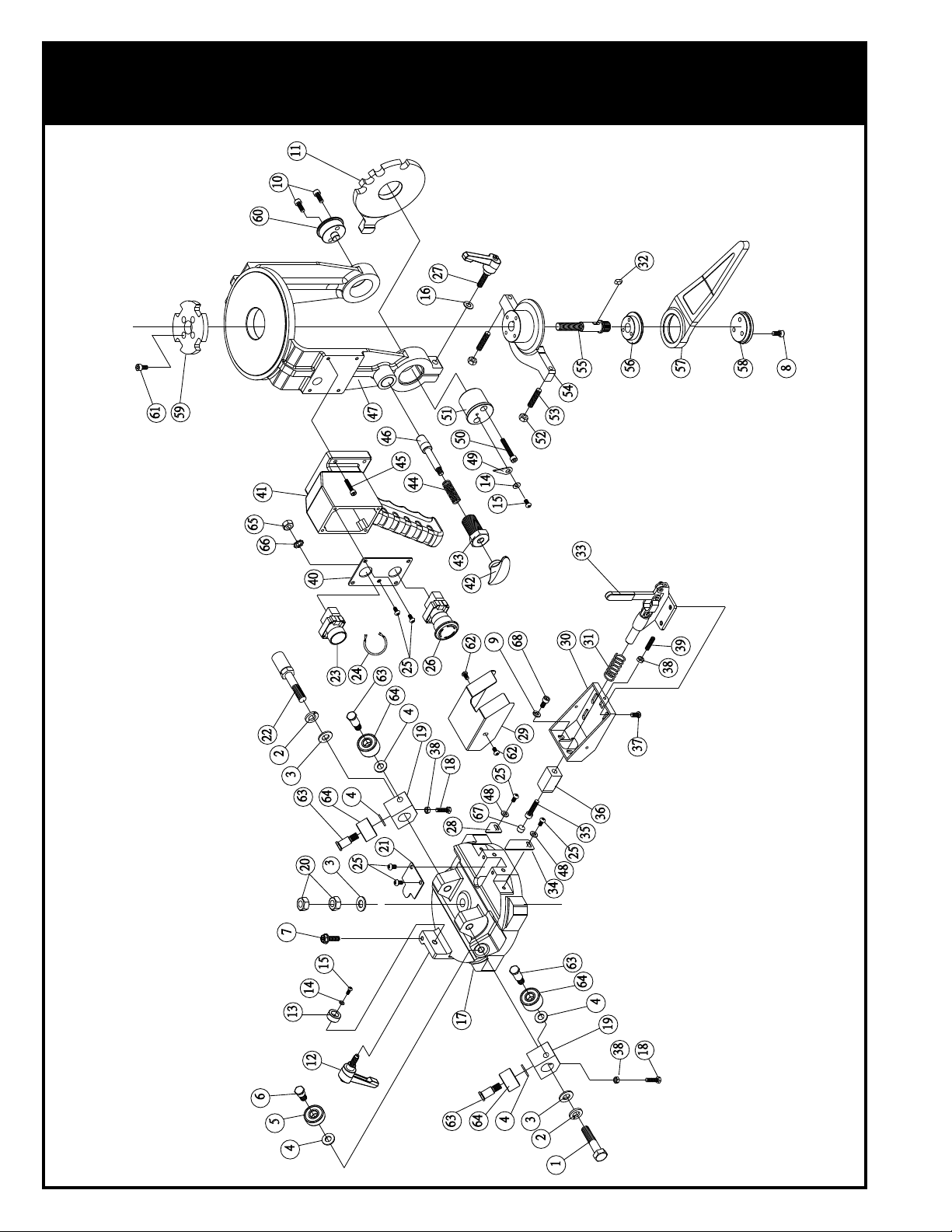
DIAGRAM D
MOTOR BRACKET - 50-755
36
Page 37

PARTS LIST D
MOTOR BRACKET - 50-755
IMPORTANT: When ordering replacement parts, always give the model number, serial number of the
machine and part number. Also a brief description of each item and quantity desired.
# PART NO. REF. NO. DESCRIPTION SPECIFICATIONS QTY
1 50755-D01 50101066 HEX BOLT M12 X 1.75P X 50L 1
2 50755-B20 50302009 LOCK WASHER M12 2
3 50755-B21 50301075 FLAT WASHER 12 X 23 X 2T 3
4 50755-A27 50301085 FLAT WASHER 10 X 20 X 2.0T 8
5 50755-D05 50501037 BEARING 6201-2RS 4
6 50755-D06 71014023 BEARING LOCK BOLT 4
7 50755-D07 50120004 FLANGE BOLT M6 X 1.0P X 20L 1
8 50755-C01 50102023 CAP SCREW M6 X 1.0P X 10L 5
9 50755-C08 50302007 LOCK WASHER M6 2
10 50755-C11 50102006 CAP SCREW M6 X 1.0P X 16L 2
11 50755-D11 71014005 ANGLE PLATE 1
12 50755-D12 50114042 LOCKING LEVER M8 X 1.25P X 24L 1
13 50755-D13 71014028 CONTACT COLLAR 1
14 50755-C32 50301078 FLAT WASHER 4.2 X 8 X 0.8T 2
15 50755-C29 50104018 SCREW M4 X 0.7P X 8L 2
16 50755-D16 50301010 FLAT WASHER 8.2 X 16 X 1T 1
17 50755-D17 71014014 MOTOR BRACKET COVER 1
18 50755-D18 50101053 HEX BOLT M6 X 1.0P X 25L 2
19 50755-D19 71014024 BEARING MOUNT 2
20 50755-C22 50201022 HEX NUT M12 X 1.75P 2
21 50755-D21 71014019 COVER PLATE 1
22 50755-D22 71014026 SUSPENSION ROD 1
23 50755-D23 51116003 ON/OFF SWITCH 22MM-1A 1
24 50755-D24 71014027 WIRE 1
25 50755-A31 50104014 SCREW M5 X 0.8P X 10L 10
26 50755-D26 51116004 EMERGENCY STOP 22MM 1
27 50755-D27 50114043 LOCKING LEVER M8 X 1.25P X 30L 1
28 50755-D28 71014022 POINTER 1
29 50755-D29 71014018 COVER 1
30 50755-D30 71014029 BASE 1
31 50755-D31 71014020 SPRING 1
32 50755-D32 50604005 KEY 5 X 5 X 12L 1
33 50755-D33 71014025 QUICK-LOCK HANDLE 1
34 50755-D34 71014021 POINTER, LONG 1
35 50755-A05 50102013 CAP SCREW M8 X 1.25P X 30L 1
36 50755-D36 71014030 POSITIONING BLOCK 1
37 50755-D37 50207020 HEX CAP SCREW M8 X 1.25P X 12L 4
38 50755-D38 50201013 HEX NUT M6 X 1.0P 3
39 50755-D39 50103016 SET SCREW M6 X 1.0P X 20L 1
40 50755-D40 71014017 ON/OFF SWITCH COVER 1
41 50755-D41 71014016 HANDLE BASE 1
42 50755-D42 71014008 POSITION LOCK KNOB 1
43 50755-D43 71014006 POSITION LOCK COLLAR 1
44 50755-D44 71014009 SPRING 1
45 50755-C05 50102021 CAP SCREW M5 X 0.8P X 25L 4
46 50755-D46 71014007 POSITION ROD 1
47 50755-D47 71014001 MOTOR MOUNTING BRACKET 1
48 50755-A33 50301107 FLAT WASHER 5 X 12 X 1T 2
49 50755-D49 35011016 POINTER 1
37
Page 38

PARTS LIST D
MOTOR BRACKET - 50-755
IMPORTANT: When ordering replacement parts, always give the model number, serial number of the
machine and part number. Also a brief description of each item and quantity desired.
# PART NO. REF. NO. DESCRIPTION SPECIFICATIONS QTY
50 50755-D50 50102047 CAP SCREW M6 X 1.0P X 40L 2
51 50755-D51 71014003 FRONT CENTRAL SHAFT 1
52 50755-A11 50201019 HEX NUT M8 X 1.25P 2
53 50755-D53 50103043 SET SCREW M8 X 1.25P X 35L 2
54 50755-D54 71014013 ADJUSTING BLOCK 1
55 50755-D55 71014012 LOCK ROD 1
56 50755-D56 71014011 LOCK HANDLE UPPER BASE 1
57 50755-D57 71014002 LOCK HANDLE 1
58 50755-D58 71014010 LOCK HANDLE LOWER BASE 1
59 50755-D59 71014015 ANGLE PLATE 1
60 50755-D60 71014004 REAR CENTRAL SHAFT 1
61 50755-D61 50102023 CAP SCREW M6 X 1.0P X 12L 3
62 50755-B15 50104044 SCREW M5 X 0.8P X 6L 2
63 50755-D63 71014031 BEARING LOCK SCREW 4
64 50755-D64 50501055 BEARING 5201-ZZ 4
65 50755-D65 50201021 HEX. NUT M5 X 0.8P 1
66 50755-D66 50303003 LOCK WASHER M5 1
67 50755-D67 71014035 POSITION ROD 1
68 50755-D68 50102056 CAP SCREW M6 X 1 X 14L 1
#
NOTES
38
Page 39

PARTS LIST E
1
MOTOR AND BLADE - 50-755
28.3
28
26
13
27
1
22
12
11
15
16
25
24
23
14
10
9
8
7
6
28.2
17
18
28.1
1
3
22
31
21
1
29
20
13
20
30
20
13
20
19
4
5
4
3
1
2
2
1
39
Page 40

PARTS LIST E
MOTOR & BLADE - 50-755
IMPORTANT: When ordering replacement parts, always give the model number, serial number of the
machine and part number. Also a brief description of each item and quantity desired.
# PART NO. REF. NO. DESCRIPTION SPECIFICATIONS QTY
1 50755-E01 71015009 LOCK KNOB 6
2 50755-E02 71015008 OUTER BLADE GUARD 2
3 50755-E03 71015011 NUT 2
4 50755-E04 50102045 CAP SCREW M6 X 1.0P X 45L 2
5 50755-E05 71015005 CHUTE GUARD (LEFT) 1
6 50755-E06 71011016 CLIP 1
7 50755-E07 71015003 BLADE LOCK NUT 1
8 50755-E08 71015002 LOCKING DISC 1
9 50755-E09 71015017 BUSHING 1
10A 50755-E10A 71015016 BLADE 12” 1
10B 50755-E10B 71015015 BLADE (OPTIONAL) 10” 1
11 50755-E11 71015001 FLANGE 1
12 50755-E12 71015004 CHUTE GUARD, RIGHT 1
13 50755-A06 50301102 FLAT WASHER 8.2 X 16 X 1T 3
14 50755-E14 50114044 LOCKING LEVER M8 X 1.25P X 35L 1
15 50755-E15 50101060 HEX BOLT M6 X 1.0P X 16L 2
16 50755-C08 50302007 LOCK WASHER M6 2
17 50755-E17 71015018 ANTI-KICKBACK MOUNTING BLOCK 1
18 50755-E18 50164002 KNOB M8 X 1.25P X 12L 1
19 50755-E19 71015014 SCREW 1
20 50755-E20 71015012 ANTI-KICKBACK PAWL 4
21 50755-E21 71015007 ANTI-KICKBACK ROD 1
22 50755-E22 71015010 INNER BLADE GUARD 2
23 50755-E23 71015006 SPLITTER 1
24 50755-C12 50301087 FLAT WASHER 6 X 12 X 1T 2
25 50755-C01 50102023 CAP SCREW M6 X 1.0P X 10L 2
26 50755-D53 50103043 SET SCREW M8 X 1.25P X 35L 2
27 50755-A11 50201019 HEX NUT M8 X 1.25P 2
28* 50755-E28A 71015551 MOTOR ASSEMBLY (M1) M1 - 2HP, 220V, 60HZ, 1PH, 2P 1
28* 50755-E28B 71015552 MOTOR ASSEMBLY (M2) M2 - 3HP, 220V, 60HZ, 3PH, 2P 1
28.1* 50755-E28.1A 71015501 MOTOR (M1) M1 - 2HP, 220V, 60HZ, 1PH, 2P 1
28.1* 50755-E28.1B 71015502 MOTOR (M2) M2 - 3HP, 220V, 60HZ, 3PH, 2P 1
28.2 50755-E28.2 50604037 KEY 5 X 5 X 16L 1
28.3 50755-E28.3 51104010 STRAIN RELIEF N-MGN20-15B-ST M20 X 1.5P 1
29 50755-E 71015019 NUT 1
30 50755-E 71015013 FRONT SPLITTER 1
31 50755-A31 50104014 SCREW M5 X 0.8P X 10L 1
40
* Check voltage/electrical specifications before ordering.
Page 41

NOTES
Page 42

8360 Champ-d’Eau, Montreal (Quebec) Canada H1P 1Y3
Tel.: (514) 326-1161
Fax: (514) 326-5565 - Parts & Service / (514) 326-5555 - Order Desk
orderdesk@general.ca
www.general.ca
Follow us:
 Loading...