

Page 1
FEATURES
Quick release combination riving style
splitter and blade guard with anti-kickback
pawls and a second European style riving
knife also included.
Large, precision-ground and polished, 40"
x 27" solid granite table with two extension
wings, for unsurpassed stability; will never
twist or warp and cannot rust or corrode.
4" dust port allows easy connection to a
dust collection system.
Large paddle-style stop switch.
Ruggedly built saw carriage with solid cast
iron, cabinet mounted trunnions.
Large motor access door for quick clean-
ing and easier maintenance.
Equipped with a sturdy, easy to adjust,T-
fence design rip fence system.
SPECIFICATIONS
BLADE DIAMETER
10” (254 mm)
ARBOR DIAMETER
5⁄8” (16 mm)
ARBOR
TILT RANGE
0° to 45° (TO LEFT)
MAXIMUM DEPTH OF CUT
AT 90°
3 3⁄16” (82 mm)
MAXIMUM DEPTH OF CUT
AT 45°
2 5⁄16” (60 mm)
D
ADO CAPACITY
3⁄4” (19 mm)
DUST POR
T DIAMETER
4” (102 mm)
ARBOR SPEED
4250 RPM
T
ABLE HEIGHT
35 3⁄4” (910 mm)
T
ABLE SIZE (W/EXTENSION WINGS)
40 x 27” (1016 x 686 mm)
T
ABLE SIZE (W/O EXTENSION WINGS)
11.5” x 27” (292 x 686 mm)
B
ASE DIMENSIONS (L x W)
19 1⁄2”x 22” (495 x 560 mm)
MO
TOR (PRE-WIRED 120 V)
1 3⁄4 HP, 120/240 V, 15/7.5 A
WEIGHT
476 LBS (216 kg)
SETUP & OPERATION MANUAL
VERSION 2 - REVISION 2 - August 26/10 (91796910)
© Copyright General® International 08/2010
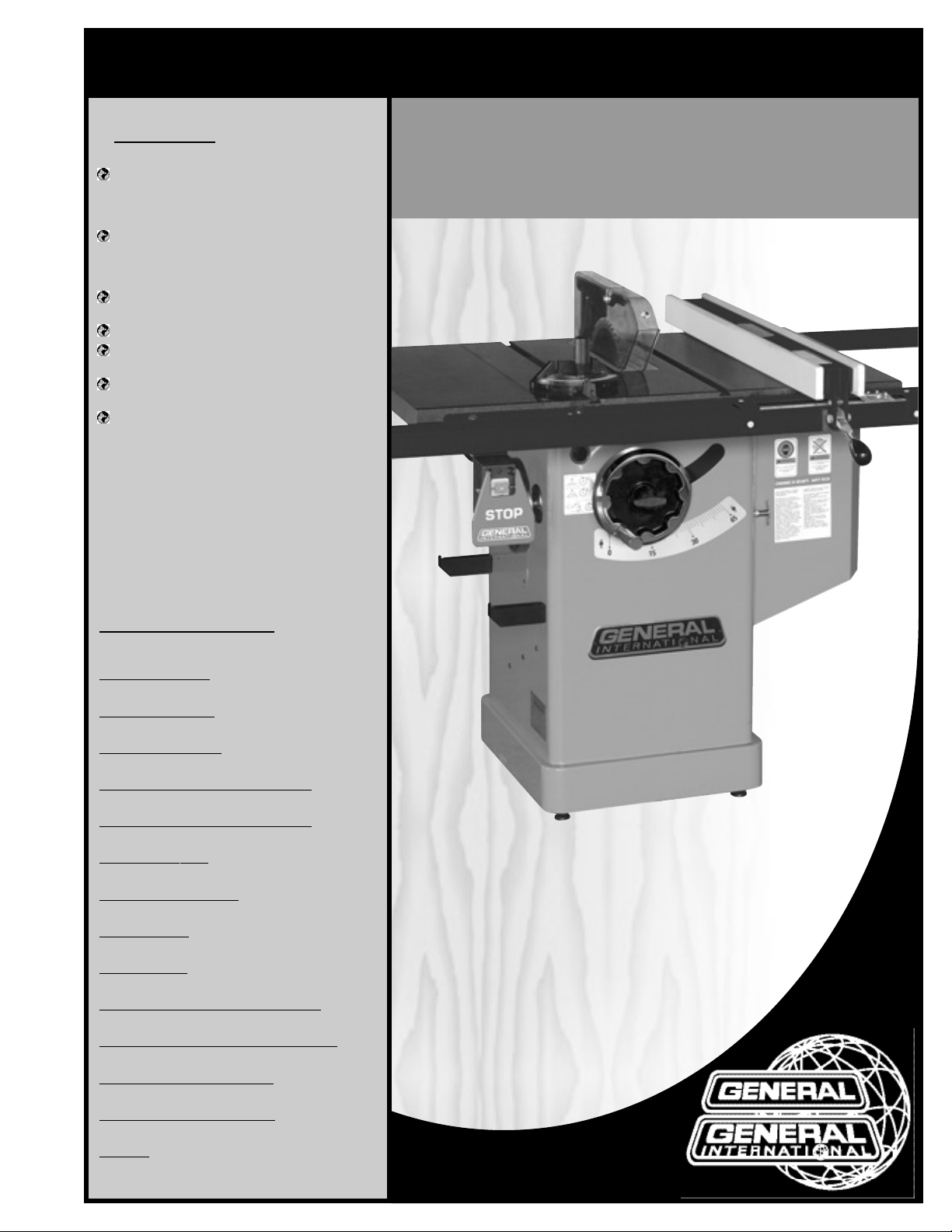
MODEL
#50-240GT M1
10” GRANITE TOP TABLE SAW
– LEFT TILT
Page 2

THANK YOU
for choosing this General®International model 50-240GT M1 10"
Granite Top Table Saw.This saw has been carefully tested and inspected before shipment and
if properly used and maintained, will provide you with years of reliable service. To ensure optimum performance and trouble-free operation, and to get the most from your investment,
please take the time to read this manual before assembling, installing and operating the unit.
The manual’s purpose is to familiarize you with the safe operation,basic function,and features
of this saw as well as the set-up,maintenance and identification of its parts and components .
This manual is not intended as a substitute for formal woodworking instruction, nor to offer the
user instruction in the craft of woodworking. If you are not sure about the safety of performing
a certain operation or procedure,do not proceed until you can confirm,from knowledgeable
and qualified sources, that it is safe to do so.
Once you’ve read through these instructions, keep this manual handy for future reference.
Disclaimer:
The information and specifications in this
manual pertain to the unit as it was supplied from the
factory at the time of printing. Because we are committed to making constant improvements, General
®
International reserves the right to make changes to components,parts or features of this unit as deemed necessary ,
without prior notice and without obligation to install any
such changes on previously delivered units.Reasonable
care is taken at the factory to ensure that the specifications and information in this manual corresponds with
that of the unit with which it was supplied. However, special orders and “after factory”modifications may render
some or all information in this manual inapplicable to
your machine. Further, as several generations of this
model of saw and several versions of this manual may
be in circulation, if you own an earlier or later version of
this unit, this manual may not depict your machine
exactly. If you have any doubts or questions contact
your retailer or our support line with the model and serial number of your unit for clarification.
GENERAL® INTERNATIONAL
8360 Champ-d’Eau, Montreal (Quebec) Canada H1P 1Y3
Telephone (514) 326-1161 • Fax (514) 326-5555 • www.general.ca
Page 3

GENERAL®MFG & GENERAL®INTERNATIONAL WARRANTY
All component parts of General® MFG, General® International and Excalibur by General
International ® products are carefully inspected during all stages of production and each unit
is thoroughly inspected upon completion of assembly.
Limited Lifetime
Warranty
Because of our commitment to quality and customer satisfaction, General® MFG and
General® International agree to repair or replace any part or component w hich upon examination, proves to be defective in either workmanship or material to the original purchaser
for the life of the tool.
However, the Limited Lifetime Warranty does not cover any product used
for professionnal or commercial production purposes nor for industrial or educational applications. Such cases are covered by our Standard 2-year Limited Warranty only. The Limited
Lifetime Warranty is also subject to the “Conditions and Exceptions”as listed below.
Standard 2-Year Limited Warranty
All products not covered by our lifetime warranty including products used in commercial,
industrial and educational applications are warranted for a period of 2 years (24 months) from
the date of purchase. General® MFG and General® Inter national agree to repair or replace
any part or component which upon examination, proves to be defective in either workmanship or material to the original purchaser during this 2-year warranty period, subject to the
“conditions and exceptions”as lis ted below.
T
o file a Claim
To file a claim under our Standard 2-year Limited Warranty or under our Limited Lifetime
Warranty, all defective par ts, components or machinery must be retur ned freight or postage
prepaid to General® International, or to a nearby distr ibutor, repair center or other location
designated by General® International. For further details call our service department at 1-888949-1161 or your local distributor for assistance when filing your claim.
Along with the return of the product being claimed for warranty, a copy of the original proof
of purchase and a “letter of claim”must be included (a warranty claim form can also be used
and can be obtained,upon request,from General® International or an authorized distributor)
clearly stating the model and serial number of the unit (if applicable) and including an explanation of the complaint or presumed defect in material or workmanship.
CONDITIONS AND EXCEPTIONS:
This coverage is extended to the original purchaser only. Prior warranty registration is not
required but documented proof of purchase i.e. a copy of original sales invoice or receipt
showing the date and location of the purchase as well as the purchase price paid, must be
provided at the time of claim.
Warranty does not include f ailures,breakage or defects deemed after inspection by General®
MFG or General® International to have been directly or indirectly caused by or resulting from;
improper use, or lack of or improper maintenance, misuse or abuse, negligence, accidents ,
damage in handling or transport, or normal wear and tear of any generally considered consumable parts or components .
Repairs made without the written consent of General® Interna tionallwill void all warranty.
Page 4

TABLE OF CONTENTS
Rules for safe operation . . . . . . . . . . . . . . .5
Electrical requirements . . . . . . . . . . . . . . .6
Grounding instructions . . . . . . . . . . . . . . . . . . . . . . .6
Circuit capacity . . . . . . . . . . . . . . . . . . . . . . . . . . . . .6
Converting the motor to 240 V . . . . . . . . . . . . . . . . .6
Extension cords . . . . . . . . . . . . . . . . . . . . . . . . . . . . .6
Identification of main parts
and components . . . . . . . . . . . . . . . . . . . .
7
Basic functions . . . . . . . . . . . . . . . . . . . . .8
Placement within the shop / Establishing a
safety zone . . . . . . . . . . . . . . . . . . . . . . . .
8
Unpacking . . . . . . . . . . . . . . . . . . . . . . . . .9
List of contents . . . . . . . . . . . . . . . . . . . . . . . . . . . . . .9
Additional requirements for set up . . . . . . . . . . . . .9
ASSEMBLY INSTRUCTIONS . . . . . . . . . . . .10-12
Install the blade tilt and blade height
adjustment hand wheels . . . . . . . . . . . . . . . . . . . .10
Install the wrench storage hook and rip fence
storage brackets . . . . . . . . . . . . . . . . . . . . . . . . . . .10
Attach the dust port . . . . . . . . . . . . . . . . . . . . . . . . .10
Install the table extension wings . . . . . . . . . . . . . .10
Level / align the extension wings with the
main table . . . . . . . . . . . . . . . . . . . . . . . . . . . . . . . .11
Install the front fence rail and guide tube . . . . . .11
Mount the switch . . . . . . . . . . . . . . . . . . . . . . . . . . .12
Attach the rear fence rail . . . . . . . . . . . . . . . . . . . .12
Align and level the rip fence . . . . . . . . .12-13
Align the rip fence parallel to the blade . . . . . . .12
Align the rip fence perpendicular (90º) to the
table . . . . . . . . . . . . . . . . . . . . . . . . . . . . . . . . . . . . .12
Level the fence . . . . . . . . . . . . . . . . . . . . . . . . . . . . .13
Adjust and Align rip fence pointer . . . . . . .13
Level the table insert . . . . . . . . . . . . . . . .13
Connecting to a dust collector . . . . . . . . . .14
Install / Remove a saw blade . . . . . . . . .14-15
Install and adjust riving knife . . . . . . . .15-16
Select a riving knife . . . . . . . . . . . . . . . . . . . . . . . . .15
Riving knife removal / installation . . . . . . . . . . . . .16
BASIC ADJUSTMENTS & CONTROLS . . . . . .16-17
Connecting to a power source . . . . . . . . . . . . . . .16
On/Off switch & safety pin . . . . . . . . . . . . . . . . . . .17
Thermal relay / circuit breaker . . . . . . . . . . . . . . .17
Blade height & tilt adjusment . . . . . . . . . .18
Blade height adjustment . . . . . . . . . . . . . . . . . . . .18
Blade tilt (bevel) adjustment . . . . . . . . . . . . . . . . .18
OPERATING INSTRUCTIONS . . . . . . . . . . .19-22
Types of cuts . . . . . . . . . . . . . . . . . . . . .19-20
Ripping . . . . . . . . . . . . . . . . . . . . . . . . . . . . . . . . . . .19
Bevel ripping . . . . . . . . . . . . . . . . . . . . . . . . . . . . . .20
Ripping small work pieces . . . . . . . . . . . . . . . . . . .20
Cross cutting . . . . . . . . . . . . . . . . . . . . . . . . . . . . . . .20
Bevel cross cutting . . . . . . . . . . . . . . . . . . . . . . . . . .20
Adjusting and using the miter gauge . . . . .21-22
Adjusting the miter gauge . . . . . . . . . . . . . . . . . . .21
Adding an auxiliary fence to the miter gauge . .21
Marking wood . . . . . . . . . . . . . . . . . . . . . . . . . . . . .21
Miter cuts . . . . . . . . . . . . . . . . . . . . . . . . . . . . . . . . . .22
Compound mitering . . . . . . . . . . . . . . . . . . . . . . . .22
Using a dado head blade . . . . . . . . . . . . . . .22
MAINTENANCE & ADJUSTMENTS . . . . . . . .22-24
Periodic maintenance . . . . . . . . . . . . . . . . . . . . . .22
Lubrication . . . . . . . . . . . . . . . . . . . . . . . . . . . . . . . .23
Adjusting the 90º bevel stop . . . . . . . . . . . . . . . . . .23
Adjusting the bevel angle pointer . . . . . . . . . . . .23
Adjusting the 45º bevel stop . . . . . . . . . . . . . . . . . .24
Replacing the drive belt . . . . . . . . . . . . . . . . . . . . .24
Pulleys parallel alignment . . . . . . . . . . . . . . . . . . .24
Recommended optional accessories . . . . .25
Parts list & diagrams . . . . . . . . . . . . . .26-35
Page 5

RULES FOR SAFE OPERATION
To help ensure safe operation, please take a moment to learn the machine’s applications and limitations, as well as potential hazards. General® International disclaims any real or implied warranty and holds itself harmless for any injury that
may result from improper use of its equipment.
1. Do not operate the saw when tired, distracted, or
under the effects of drugs, alcohol or any medication that impairs reflexes or alertness.
2. The working area should be well lit, clean and free
of debris.
3. Keep children and visitors at a safe distance when
the saw is in operation; do not permit them to
operate the saw.
4. Childproof and tamper proof your shop and all
machinery with locks, master electrical switches
and switch keys, to prevent unauthorized or unsupervised use.
5. Stay alert! Give your work your undivided attention.Even a momentary distraction can lead to serious injury.
6. Fine particulate dust is a carcinogen that can be
hazardous to health. Work in a well-ventilated area
and whenever possible use a dust collector and
wear eye,ear and respiratory protection devices.
7. Do not wear loose clothing,gloves,bracelets, necklaces or other jewelry while the saw is in operation.
Wear protective hair covering to contain long hair
and wear non-slip footwear.
8. Be sure that adjusting wrenches, tools, drinks and
other clutter are removed from the machine and/or
the feed table surface before operating.
9. Keep hands well away from the blade and all moving parts. Use a br ush, not hands, to clear away
chips and dust.
10. Be sure that the blade is securely installed and in
proper cutting direction before operation.
11. Be sure the blade has gained full operating speed
before beginning to cut.
12. Always use a clean, properly sharpened blade.
Dirty or dull blades are unsafe and can lead to
accidents.
13. If using a power feeder,stop the feeder before stopping the table saw.
14. Do not push or force stock into the blade. The saw
will perform better and more safely when working
at the rate for which it was designed.
15. Use suitable suppor t when cutting stock that does
not have a flat surface. Always hold stock firmly
against the fence when ripping,or against the miter
gauge when cross-cutting.
16. To minimize risk of injury in the event of workpiece
kickback,never stand directly in-line with the blade
or in the potential kickback path of the work piece.
17. Avoid working from awkward or off balance positions. Do not overreach while cutting; keep both
feet on floor. Never lean over or reach over the
blade and never pull the work piece o ver the blade
from behind.Use out feed support or have an assistant help when ripping long material.
18. Keep blade guards in place and in working order.
If a guard must be removed for maintenance or
cleaning, be sure it is properly reattached before
using the tool again.
19. Never leave the machine running with the power
on when not in operation.
20. Use of parts and accessor ies NOT recommended
by
GENERAL® INTERNATIONAL
may result in equip-
ment malfunction or risk of injury.
21. Never stand on machinery. Serious injury could
result if the tool is tipped over or if the blade is unintentionally contacted.
22. Always disconnect tool from pow er before servicing
or changing accessories such as blades, or before
performing any maintenance, cleaning or adjustments, or if the machine will be left unattended.
23. Make sure that switch is in "OFF" position before
plugging in the power cord.
24. Make sure the tool is properly grounded. If equipped with a 3-prong plug it should be used with a
three-pole receptacle. Never remove the third
prong.
25. Do not use this saw for other than its intended use. If
used for other purposes,
GENERAL® INTERNATIONAL
disclaims any real implied warranty and holds itself
harmless for any injury, which may result from that
use.
5
Page 6

ELECTRICAL REQUIREMENTS
GROUNDING INSTRUCTIONS
In the event of an electrical malfunction or short circuit,
grounding reduces the risk of electric shock. The motor
of this machine is wired for 120V single phase operation
and is equipped with a 3-conductor cord and a 3prong grounding plug to fit a grounded type receptacle . Do not remove the 3rd prong (grounding pin)
to make it fit into an old 2-hole wall socket or extension
cord. If an adaptor plug is used , it must be attached
to the metal screw of the receptacle.
Note: The use of an adaptor plug is illegal in some
areas. Check your local codes. If you have any doubts
or if the supplied plug does not correspond to your electrical outlet, consult a qualified eletrician before proceeding.
CIRCUIT CAP
ACITY
Make sure that the wires in your circuit are capable of
handling the amperage draw from your machine, as
well as any other machines that could be operating on
the same circuit. If you are unsure, consult a qualified
electrician. If the circuit breaker trips or the fuse blows
regularly, your machine may be operating on a circuit
that is close to its amperage draw capacity.However ,if
an unusual amperage draw does not exist and a
power failure still occurs,contact a qualified technician
or our service depar tment.
BEFORE CONNECTING THE MACHINE TO THE POWER SOURCE,VERIFY THAT THE VOLTAGE OF YOUR PO WER SUPPLY CORRESPONDS
WITH THE VOLTAGE SPECIFIED ON THE MOTOR I.D. NAMEPLATE. A POWER SOURCE WITH GREATER VOLTAGE THAN NEEDED CAN
RESULT IN SERIOUS INJURY TO THE USER AS WELL AS DAMAGE TO THE MACHINE. IF IN DOUBT ,CONTACT A QUALIFIED ELECTRICIAN
BEFORE CONNECTING TO THE POWER SOURCE.
THIS TOOL IS FOR INDOOR USE ONLY. DO NOT EXPOSE TO RAIN OR USE IN WET OR DAMP LOCATIONS.
CONVERTING THE MOTOR TO 240V
Should you need to conv ert your machine’ s motor from
120V to 240V power, there is an electrical schematic
drawing on the inside of the motor cover plate. Unless
you are a qualified electrician, we do not recommend
attempting this conversion on your own. If you choose
to do so, you may risk serious personal injur y, damage
to the motor and voiding the warranty of y our machine.
We suggest you ask your local General International
distributor to recommend qualified electricians in your
area (or perhaps one of their own technicians) who
can make this conversion properly and safely.
EXTENSION CORDS
If you find it necessary to use an extension cord with your
machine, use only 3-wire extension cords that have 3prong grounding plug and a matching 3-pole receptacle that accepts the tool’s plug. Repair or replace a
damaged extension cord or plug immediately.
Make sure the cord rating is suitable for the amperage
listed on the motor I.D. plate. An undersized cord will
cause a drop in line voltage resulting in loss of power
and overheating. The accompanying chart shows the
correct size extension cord to be used based on cord
length and motor I.D. plate amp rating. If in doubt, use
the next heavier gauge. The smaller the number, the
heavier the gauge.
TABLE - MINIMUM GAUGE FOR CORD
AMPERE
RATING
TOTAL LENGTH OF CORD IN FEET
120 VOLTS 25 FEET 50 FEET 100 FEET 150 FEET
240 VOLTS 50 FEET 100 FEET 200 FEET 300 FEET
AWG
< 5
------->
18 16 16 14
6 TO 10
------->
18 16 14 12
10 TO 12
------->
16 16 14 12
12 TO 16
------->
14 12 * NR * NR
* NR = Not Recommended
6
Page 7

10” GRANITE TOP TABLE SAW - LEFT TILT
50-240GT M1
IDENTIFICATION OF MAIN PARTS AND COMPONENTS
LEFT TABLE EXTENSION WING
MAIN TABLE
MITER GAUGE
SPLITTER/BLADE GUARD ASSEMBLY
RIP FENCE
REAR FENCE RAIL
RIGHT TABLE EXTENSION WING
FRONT FENCE RAIL
MOTOR COVER DOOR
HEIGHT ADJUSTMENT HAND WHEEL
BLADE TILT ANGLE SCALE
LEVELING FEET
ON/OFF POWER SWITCH
BLADE TILT ADJUSTMENT HAND WHEEL
WRENCH STORAGE HOOK
RIP FENCE STORAGE BRACKETS
DUST PORT
7
LEFT SIDE VIEW
Page 8

BASIC FUNCTIONS
PLACEMENT WITHIN THE SHOP /
ESTABLISHING A SAFETY ZONE
PLACEMENT WITHIN THE SHOP
This machine should be installed and operated only on a
solid,flat and stable floor that is able to support the weight
of the saw and the operator.
Plan for placement within your shop that will allow the
operator to work unencumbered and unobstructed by
foot traffic (either passing shop visitors or other shop workers) or other tools or machinery.
Note: Install the 4 supplied leveling feet Aunder the saw cabinet before final placement of the saw. Adjust the leveling feet
as needed to level the saw with the floor.
ESTABLISHING A SAFE
TY ZONE
For shops with frequent visitors or multiple operators, it is
advisable to establish a safety zone around shop machinery. A clearly defined “no-go” zone on the floor around
each machine can help avoid accidents that could cause
injury to either the operator or the shop visitor. It is advisable to take a few moments to either paint (using non-slip
paint) or using tape,define on the floor the limits or perimeter of each machines safety zone.Take steps to ensure that
all operators and shop visitors are aware that these areas
are off limits whenever a machine is running for everyone
but the individual operating the unit.
THIS MODEL 50-240GT 10" GRANITE TOP TABLE SAW IS HEAVY. DO NOT OVER-EXERT. A HOIST OR FORKLIFT WITH STRAPS SHOULD
BE USED TO LIFT THIS MACHINE.
TO LIMIT THE RISK OF SERIOUS INJURY OR DAMAGE TO THE MACHINE,ANY EQUIPMENT USED TO LIFT THIS MACHINE SHOULD HAVE
A RATED CAPACITY IN EXCESS OF 476 LBS (216 KG).
8
This cabinet saw has been designed for cutting solid wood as well as manufactured wood materials such as plywood,wood panelling,particleboard, mdf and other wood based by-products.This saw is not designed for cutting
metals nor for cutting any materials other than wood or wood based stock.
This saw is designed for use with maximum 10" (254 mm) diameter blades having a center hole diameter of 5/8".
The blade can be raised to cut a maximum stock thickness of 3 3/16" with the blade set 90 degrees to the table.
The blade can be tilted up to 45 degrees to the left for bevel cuts to a maximum stock thickness of 2 5/16". Using
any standard aftermarket 8" diameter stacked dado blade set (not included),the maximum dado cutting capacity of this saw is 3/4".
Note: for safer dado cutting, an optional dado table insert (part number #50-241) can be purchased through your General
International distributor.
The 50-240GT is supplied with both a riving style splitter/blade guard assembly and a European style riving knife that
are both designed to raise or lower and tilt with the blade,and maintain a consistent distance to the blade at all
times, regardless of the height or angle of the blade. This can help reduce (but not totally eliminate) the risk of a
kickback incident,where the workpiece is thrown back at the operator by helping to prevent the workpiece from
getting stuck between the blade and the riving style splitter or riving knife (as compared to a traditional stationary
splitter) or from closing up on the back of the blade as it passes through the cut.
A
Page 9
UNPACKING
Carefully unpack and remove the saw and its components from the box and check for damaged or missing
items as per the list of contents below.
NOTE: Please report any damaged or missing items to your
General® International distributor immediately.
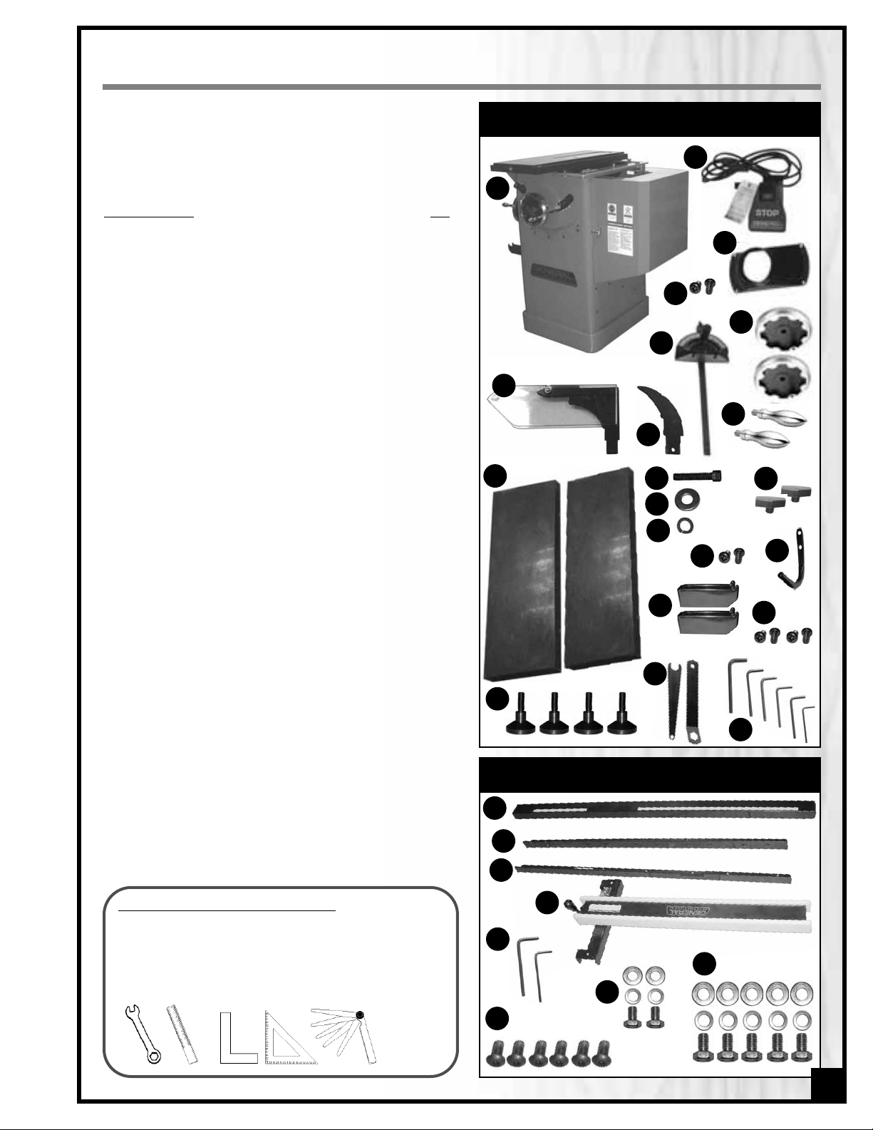
LIST OF CONTENTS
QTY
SAW AND OTHER COMPONENTS
A - TABLE SAW ..................................................................................1
B - ON/OFF POWER SWITCH ...........................................................1
C - DUST PORT ...................................................................................1
D - SELF-TAPPING SCREW .................................................................2
E - SPLITTER / BLADE GUARD ASSEMBLY
.........................................1
F - RIVING KNIFE
..............................................................................1
G - MITER GAUGE.............................................................................1
H - HAND WHEEL ..............................................................................2
I - HAND WHEEL HANDLE................................................................2
J - TABLE EXTENSION WING (LEFT & RIGHT) ...................................2
K - 5/16-18 X 1.7”CAP SCREW ........................................................8
L - FLAT WASHER...............................................................................8
M - LOCK WASHER............................................................................8
N - HAND WHEEL LOCK KNOB........................................................2
O - SELF-TAPPING SCREW.................................................................2
P - WRENCH STORAGE HOOK.........................................................1
Q - RIP FENCE STORAGE BRACKET...................................................2
R - SELF-TAPPING SCREW.................................................................4
S - LEVELING FOOT..........................................................................4
T - ARBOR WRENCH & OPEN END WRENCH.................................2
U - ALLEN KEY (2.5-3-4-5-6-MM & 1/8”)..........................................6
FENCE & RAILS
a - GUIDE TUBE .................................................................................1
b - FRONT RAIL.................................................................................1
c - REAR RAIL....................................................................................1
d - RIP FENCE ...................................................................................1
e - ALLEN KEY (3/16” & 4 MM) .......................................................2
f - SOCKET SCREW..........................................................................6
g - M6X10 MM HEX HEAD BOLT W/LOCK & FLAT WASHER...........2
h - 1/4-20X3/4 HEX HEAD BOLT W/LOCK & FLAT WASHER............5
ADDITIONAL REQUIREMENTS FOR SET UP
• 13 mm wrench
• Straightedge
• Machinist square or triangle square
• Feeler gauge
OR
SAW AND OTHER COMPONENTS
FENCE & RAILS
9
A
E
B
C
F
G
H
I
J
K
N
P
Q
L
M
S
T
U
a
b
c
d
f
g
e
h
D
8X
8X
8X
R
O
Page 10
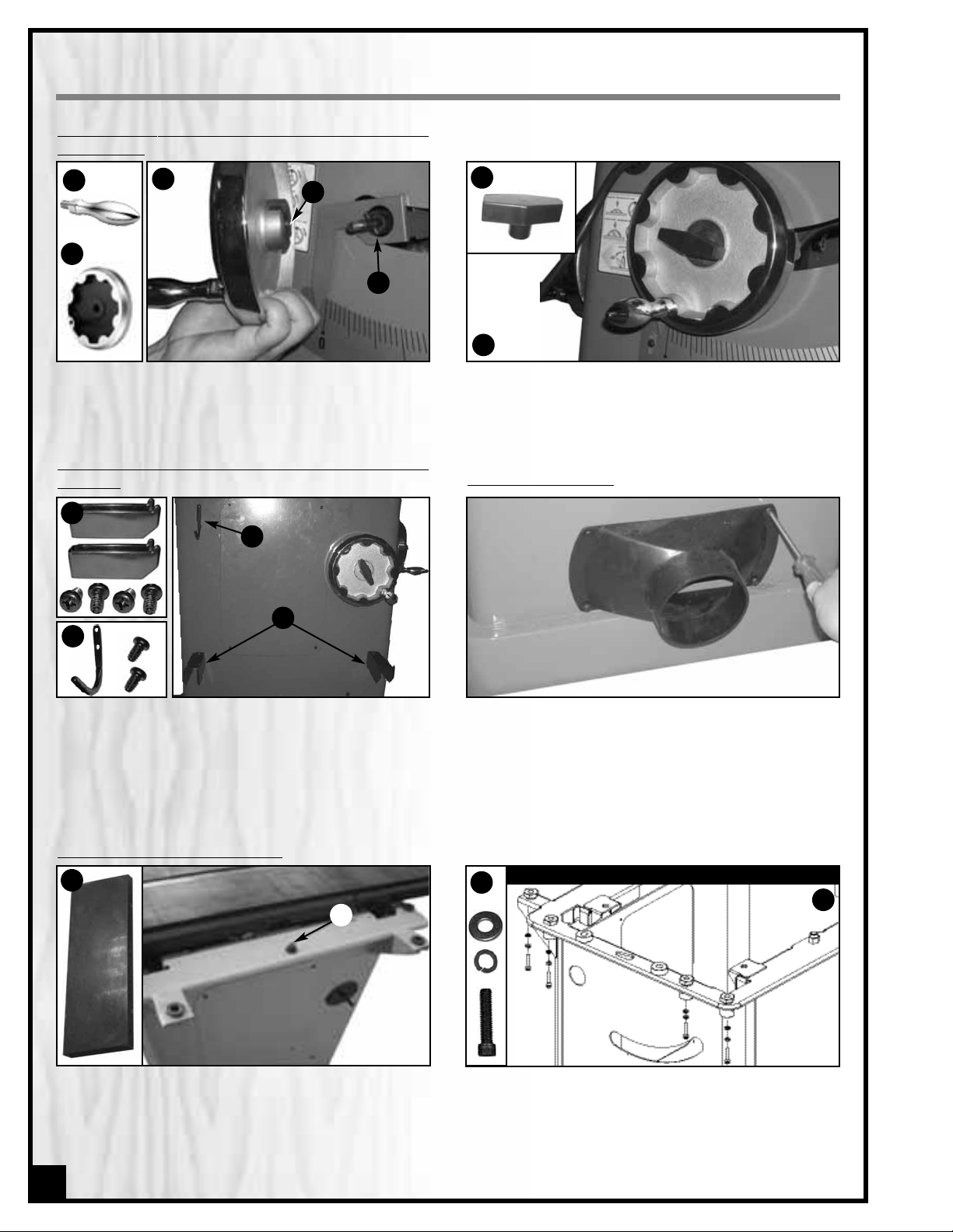
INSTALL THE BLADE TILT AND BLADE HEIGHT ADJUSTMENT
HAND WHEELS
ASSEMBLY INSTRUCTIONS
1. Attach the two rip fence storage brackets A on the
left side of the cabinet as shown in B, using four
self-tapping screws.
2. Attach the wrench storage hook C on the left side
of the cabinet as shown in D using two self-tapping
screws.
A
1. Thread a handle A onto each hand wheel B, then
install one hand wheel onto the shaft at the front of
the saw as shown in C.The slots in the hand wheel
D must be aligned with the spring pin on the shaft E.
2. Install a lock knob F into the hand wheel shaft
as shown in G to secure the hand wheel in place.
3. Repeat with the second hand wheel, on the shaft
located on the left side of the saw cabinet.
F
C
E
G
A
INST
ALL THE WRENCH STORAGE HOOK AND RIP FENCE STORAGE
BRACKE
TS
C
B
D
ATTACH THE DUST PORT
Attach the dust port to the opening in the bottom rear
of the cabinet with four self-tapping screws.
B
1. With the help of an assistant, install the left table
extension wing A on the left side of the cabinet by
placing the left wing on top of the cabinet (the fixing pin B must be inser ted in the hole under the
wing).
INST
ALL THE TABLE EXTENSION WINGS
10
A
SHOWN WITHOUT TABLE AND WING FOR CLARITY ONLY
C
D
2. Attach the table extension wing to the cabinet
using 4 cap screws, lock washers and flat washers
C in the assembly order shown in D, then tighten
the 4 cap screws with the supplied 6 mm Allen key.
3. Repeat steps 1 and 2 with the right table extension
wing on the right side of the main table.
B
D
Page 11

E
1. Place a straightedge on the table and extension
to align the extension wing and then tighten down
the 4 screws with the supplied 6 mm Allen key
Note: Be sure that the table extension wing is flush with the
front edge of the table.
2. Place the straightedge on the table and extension
again, using a feeler gauge to make sure the
extension wing is perfectly leveled with the main
table.
1. Starting from the left, attach the front fence rail to
the front of the table with 3 flat head socket screws
A,aligning the 3 holes in the table (1 in each wing
and 1 in the main table) with the holes in the rail as
shown.
INSTALL THE FRONT FENCE RAIL AND GUIDE TUBE
A
B
2. Attach the guide tube to the front fence rail by fas-
tening 5 hex head bolts,lock washers and flat w ashers B to the underside of the rail C.For now, omit the
first two holes on the far left of the rail D because this
is where you will attach the saw’s On/Off switch.
Note: when the tube is attached, there will be a gap of
about 1 inch between it and the rail,E,in which part of the
fence will ride.
C
D
11
level here
flush here
LEVEL / ALIGN THE EXTENSION WINGS WITH THE MAIN TABLE
The wings have been factory set to be leveled with the main table upon assembly. However we recommend that you verify that the wings are perfectly leveled with the top of the main table and aligned with the front edge of the main table
prior to first use. Proceed as follows:
F
4. Adjust the 4 elevation screws F using the supplied
open end wrench to raise or lower the extension
wing. Re-tighten the 4 set screws E and 4 cap
screws D.
Note: When tightening the cap screws D, take care not to
undo the previous alignment. Reverify the table alignment
and readjust if needed.
5. Repeat steps 1 to 4 with the other extension wing.
E
3. If needed, fine tune by slightly loosening the 4 cap
screws D (see previous page) then loosening the
4 set screws E,using the supplied 2.5 mm Allen key.
E
F
Page 12

MOUNT THE SWITCH
Attach the switch to the underside of the front rail A
using two hex head bolts, lock washers and flat washers, aligning it with the two holes on the far left of the
rail B.
Note: Do not connect the female end of the power cord
from the switch to the motor yet.
ATTACH THE REAR FENCE RAIL
Attach the rear fence rail to the rear of the table with 3
flat head socket screws C, aligning the 3 holes in the
table (1 in each wing and 1 in the main table) with the
holes in the rail as shown.
C
ALIGN AND LEVEL THE RIP FENCE
THE RIP FENCE MUST BE PARALLEL TO THE BLADE DURING OPERA TION.FAILURE TO SET THE RIP FENCE PARALLEL TO THE BLADE CAN
RESULT IN KICKBACK AND POSSIBLE SERIOUS INJURY.
ALIGN THE RIP FENCE PARALLEL TO THE BLADE
1. Slide the fence over to the right T-slot on your saw
table top A. Lock down the fence handle B and
make a visual check that the fence is parallel with
the T-slot all along its length.
Tip: Also, you can place a small 3/4” thick block of wood,
upright into the T-slot and slide it from the front to the bac k
checking its distance from the left edge of the fence.
2. If the fence is not parallel, it can be adjusted by
using the supplied 4” Allen key to turn one or
both of the screws C. Do this slowly, just an eighth
to a quarter turn at a time, or you will quickly overshoot the desired adjustment.
Note: It is always good practice to periodically recheck
the alignment of your fence to the blade.
A
B
ALIGN THE RIP FENCE PERPENDICULAR (90°) TO THE TABLE
Place a machinist square on the table against the fence A and look for a gap between the square and the
fence (bottom and top) or the table. If needed, adjust
either of the two plastic set screws B,to tilt the fence
slightly and square it to the table.
To make satisfactory rip cuts, your fence must be aligned perfectly parallel with the saw blade.
12
C
C
A
B
A
B
B
Page 13

LEVEL THE FENCE
The fence should be parallel to the table and sit
approximately 2 mm above the table’s surface (so the
fence will not scratch the table and a thin work piece
will not get stuck or jammed under the fence).
To level and adjus t the height of the fence:
1. Loosen the hex nut E on the leveling foot F located
under the rear end of the fence.
2. Raise or lower the leveling foot until there is 2 mm
(approx.) between the bottom of the fence and
the table, then tighten the hex nut to lock the setting of the leveling foot.
3. If needed, to level the fence,adjust the 2 plastic set
screws G equally, thereby raising or lowering the
front of the fence an equal amount on either side
so as not to undo the previous perpendicular
adjustment.
NOTE: To remove any remaining play between the fence
mounting bracket and guide tube, ajust the two plastic
screws Hfor fine tuning as needed.
F
E
Set blade to 90° and raise it to the maximum height.
Move the fence till it lightly touches the right side of the
blade and push down the locking lever to lock the
fence in place.
With the fence locked in place against the blade,
loosen the pointer screws A. Line up the reference line
on the pointer with the zero point on the tape and retighten the pointer screws.
Note: When changing blades, re-align the pointer with the
zero points on the tapes to account for thinner or thicker
blades.
ADJUST & ALIGN RIP FENCE POINTER
LEVEL THE TABLE INSERT
Use a straightedge to determine whether the insert is
level with the table top. Turn each of the 5 adjusting
screws A with the supplied 3 mm Allen wrench until
done.
Suggestion: Start by adjusting one rear screw and its
diagonal opposite in front, then tweak the remaining
screws.
Note: If the sawblade has already been installed, use the
raising hand wheel to lower the blade below the table surface before leveling the insert.
A
13
G
G
H
H
A
Page 14

14
BE SURE THE SAW IS UNPLUGGED AND COMPLETELY DISCONNECTED FROM THE POWER SOURCE WHENEVER INSTALLING OR
REMOVING A SAW BLADE!
NOTE: This saw is intended for use with 10" (254 mm) diameter or less saw blades having a center hole diameter of 5/8". There are many types of blades available to perform specific cutting jobs , such as crosscuts or
ripping only, or for use with plywood, panelling and other products. A good quality specialty blade can produce a finer finish, be more efficient and place less strain on the saw. Use only saw blades designed for operating speeds of 4250 RPM or higher. Saw blades should be kept clean and sharp. Never store saw blades by
stacking them directly in contact with each other .Place a layer of cardboard or similar material between the
blades to keep them from coming into contact with each other.
INSTALL A SAW BLADE
1. Unscrew and remove the 3 retaining screws, then
remove the table insert.
INSTALL / REMOVE A SAW BLADE
2. Loosen the arbor nut A with the supplied arbor
wrenches B and remove the arbor nut & flange C.
CONNECTING TO A DUST COLLECTOR
• There is a 4" dust outlet located on the lower rear of
the saw cabinet allowing for the connection to a
dust collection system (not included).
• Be sure to use appropriate size hose and fittings (not
included) and check that all connections are sealed
tightly to minimize airborne dust.
• If you do not already own a dust collection system
consider contacting your General® International distributor for information on our complete line of dust
collection systems and accessories or visit our web
site at www.general.ca
A
ALWAYS TURN ON THE DUST COLLECTOR BEFORE
STARTING THE SAW AND ALWAYS STOP THE SAW
BEFORE TURNING OFF THE DUST COLLECTOR.
B
C
Page 15

15
5. T
o remove a saw blade:
Perform the same procedure turning the arbor nut in the opposite direction or
wedge a block of wood between the teeth in front of
the saw and pull the arbor wrench toward you, or
counter-cloc kwise.
NOTE
When tightening the arbor nut, take care not to over tighten as this will make it very difficult to remove later.
Because the rotation of the blade runs counter to the direction of the threads on the nut, the blade is essentially tightening itself to the nut whenever the saw is running. Though there are no hard and fast rules for how
much torque is required, the arbor nut should be always tightened hand-tight and just slightly beyond “snug”.
3. Install a saw blade on the arbor so that the openings
between the teeth face the front of the saw (the blade spins in the counter-clockwise direction).
FRONT
BLADE DIRECTION
4. Replace the flange and arbor nut. With 1 arbor
wrench,hold the arbor from the opposite side of the
blade, so the blade & arbor won’t turn as you
tighten the arbor nut clockwise with the second
wrench.
SELECT A RIVING KNIFE
Two riving knives are provided:
- A European style riving knife without blade guard A;
- A combination riving style splitter and blade guard
with anti-kickback pawls B.
The riving knife must always be used with a blade
guard.If you already own an independently attached
blade cover such as our Excalibur 50-EXBC10, use the
riving knife A.If you do not already own a blade co ver,
use the splitter/blade guard assembly B
.
THE BLADE MUST NEVER REMAIN EXPOSED WHEN USING THE SAW. TO PREVENT THE RISK OF SERIOUS INJURIES, ALWAYS
COVER THE BLADE WITH A BLADE COVER OR GUARD.
INSTALL AND ADJUST RIVING KNIFE
B
LOOSEN
TIGHTEN
A
BE SURE THE SAW IS UNPLUGGED AND COMPLETELY
DISCONNECTED FROM THE POWER SOURCE WHENEVER INSTALLING OR REMOVING A SAW BLADE!
Page 16

RIVING KNIFE REMOVAL / INSTALLATION
ALWAYS TURN OFF AND UNPLUG THE SAW BEFORE
REMOVING / INSTALLING A RIVING KNIFE.
A
B
1. Set the blade to 90º and raise it to its highest posi-
tion. (Refer to “Blade height and tilt adjustment”
instructions on page 18 if needed).
2. Remove the table insert.
3. If already installed, remove the splitter or riving
knife by loosening the lock knob A and pulling on
it to get the locking pin out B, then pulling the splitter or riving knife up out of its mounting bracket.
4. T
o install: Loosen the lock knob A then pull on it to
get the locking pin out B. Fit the bottom end of the
splitter or riving knife into the slot in the mounting
bracket and push downward until it bottoms out
then tighten the lock knob.
5. Re-install the table inser t.
BASIC ADJUSTMENTS & CONTROLS
CONNECTING TO A POWER SOURCE
D
MAKE SURE THAT THE POWER CORD LIES ON THE
BOTTOM OF THE CABINET
D, AWAY FROM THE SAW
BLADE AND ANY BLADE HEIGHT/BLADE TILT MECHANISM PINCH POINT
.
1. Pass the switch power cord through the hole in
front of the saw cabinet A.
2. Unscrew and remove the 4 screws on the left side
of the cabinet B, then remove the access panel.
3. Connect the switch 3-prong plug to the motor inlet
plug C.
C
A
B
TO AVOID UNEXPECTED OR UNINTENTIONAL START-UP,
MAKE SURE THAT THE POWER SWITCH ON THE SAW IS
IN THE OFF POSITION BEFORE CONNECTING TO A
POWER SOURCE.
TO AVOID RISK OF SHOCK OR FIRE DO NOT OPERATE
THE UNIT WITH A DAMAGED POWER CORD OR PLUG.
REPLACE DAMAGED CORD OR PLUG IMMEDIATELY.
SWITCH OFF
4 Plug the power cord into an appropriate outlet E.
Refer back to the section entitled “ELECTRICAL
REQUIREMENTS” and make sure all requirements
and grounding instructions are followed.
E
16
Page 17

ON/OFF SWITCH & SAFE
TY PIN
T
o start the machine
Lift the red stop switch panel and remove the lock-out
pin.Lower the stop panel and push the green “ON”button. Wait for the saw blade to reach full speed before
cutting.
T
o stop the machine
Push on the RED “STOP” panel and wait for the blade to
come to a complete stop.
The ON/OFF switch assembly F is equipped with a lockout safety pin G. When the pin is installed through the
green “on”button H, the machine cannot be star ted.
THERMAL RELAY / CIRCUIT BREAKER
The unit is equipped with a thermal relay (circuit breaker) located on the right of the power switch to protect the motor
from power surges or spikes in line voltage. In the event of a power surge, the ther mal relay will be automatically
tripped thereby cutting off the power to the motor.
Note: The most common causes of such overloads are:
1. Overworking the motor by attempting to cut thick stock at too high a feed rate, thereby causing an
increase in power consumption and a spike in amperage draw.
2. An electrical extension cord that is too long or not the correct gauge of wire, w hich can also cause an
increase in amperage draw. If an electric extension cord must be used, refer to the chart in the electrical
requirements section at the beginning of this manual.
3. Overworked circuit caused by operating on a circuit that is close to its amperage draw capacity. Make
sure the circuit being used is capable of handling the amperage draw from this machine as well as any
other electrical devices operating on the same circuit. If you are unsure, consult a qualified electrician.
When you have finished using the machine be sure to re-install the lock-out pin and unplug the saw from the
power source.
TO AVOID UNEXPECTED OR UNINTENTIONAL START-UP BE CERTAIN THA T THE PO WER SWITCH HAS BEEN SET TO THE OFF POSITION
BEFORE RE-SETTING THE THERMAL RELAY.
To reset the thermal relay after it has been tripped:
Set the power switch to the “off” position and press the
thermal relay reset button I, then res tar t the machine.
SWITCH OFF
G
H
I
17
F
Page 18

BL
ADE HEIGHT ADJUSTMENT
The blade height adjustment hand wheel is located on
the front of the saw A and there is a lock knob B on the
hand wheel that allows you to lock the wheel and secure
the blade at the desired height.
To raise or lower the blade:
1. Loosen the lock knob B by turning counter clockwise.
2. T
o raise the blade: turn the hand wheel A clockwise.
T
o lower the blade: turn the hand wheel counter
clockwise.
3. With the blade set to the desired height, tighten the
lock knob B to lock the blade in position.
TO LIMIT YOUR EXPOSURE TO THE BLADE AND ALSO TO MAXIMISE THE EFFECTIVENESS OF THE ANTI-KICKBACK
P AWLS (WHEN USING THE RIVING STYLE SPLITTER & BLADE GUARD), NEVER TAKE MORE BLADE HEIGHT THAN
IS REQUIRED TO COMPLETE THE CUT. WHEN SETTING THE BLADE HEIGHT FOR THROUGH-CUTS (CUTS ALL THE
WAY THROUGH THE THICKNESS OF A BOARD) SET THE HEIGHT OF THE BLADE TO ROUGHLY 1/4" HIGHER
THAN THE THICKNESS OF THE BOARD.
BLADE TILT (BEVEL) ADJUSTMENT
The blade tilt (bevel) adjustment hand wheel is located
on the left side of the saw C and there is a lock knob D on
the hand wheel that allows you to lock the wheel and
secure the blade at the desired angle.
To change the angle of the blade:
1. Loosen the bevel lock knob D by turning it counterclockwise.
2. Turn the hand wheel C left or r ight as required to set
the blade to the desired angle. The blade can be tilted to the left anywhere from 0° (90° to the table) to
45°.
3. With the blade tilted to the desired angle, tighten the
lock knob by turning it clockwise to lock the tilting
mechanism and secure the blade.
BLADE HEIGHT & TILT ADJUSTMENT
B
A
C
D
18
Page 19

• Make sure that the arbor nut is secure and that the blade is firmly tightened snug on the arbor.
• Check that the blade angle and height lock knobs are tight.
• If ripping, make sure the fence lock lever is engaged and that the fence is parallel to the blade.
• If cross cutting,make sure the miter gauge is locked tight.
• While using the saw, be sure to wear safety glasses at all times.
• Make sure that the blade guard/splitter assembly or riving knife is properly installed and that the anti-kickback
pawls are functioning.
OPERATING INSTRUCTIONS
VERIFY ALL CHECK POINTS BEFORE STARTING. FAILURE TO COMPLY CAN RESULT IN SERIOUS INJURIES.
RIPPING
Cutting a wood plank or sheet of plywood lengthwise to
reduce its width is called “r ipping.” To rip stock, hold the
work with both hands pushing it into the blade as well as
firmly against the rip fence so that it is cut straight A.
• The work to be cut must have a straight edge to ride
the fence and must be flat to make solid contact with
the table during the cut in order to avoid “kickback”(a
blade jam causing the wood to fly backwards and hit
you).
• Never rip or cut wood without using the fence or miter
gauge to guide it because the stock could kickback.
• Always use the blade guard and splitter assembly when cutting wood.It has anti-kickback fingers and a splitter
to prevent the saw “kerf” (the slit cut by the blade) from closing and binding the blade, which can overload
and/or stall the motor or cause the blade to lift and eject the workpiece towards the front of the saw at v ery high
speeds. The blade guard keeps your fingers away from the blade and also reduces the amount of sawdust flying free.
• Although certain operations require the removal of the blade guard and splitter assembly, it should always be
replaced for regular cutting.
• Never stand in the line of the blade when ripping.
• Raise the saw blade only about 1/4" higher than the workpiece to be cut.
As you complete the rip, the wood will either remain on the table, tilt up to be caught on the end of the guard, or
fall onto the floor (or outfeed table).The waste par t of the s tock remains on the table to be removed only after the
saw is stopped (unless it is large enough for immediate safe removal).
TYPES OF CUTS
NEVER REACH IN TOWARDS THE BLADE WHILE THE BLADE IS STILL SPINNING! WHENEVER A RIP CUT IS COMPLETED,TURN OFF
THE SAW AND WAIT FOR THE BLADE TO COME TO A COMPLETE STOP BEFORE REACHING IN TO REMOVE THE WORKPIECE OR
THE WASTE MATERIAL.
19
A
Page 20

If the work to be ripped is narrow, it is safer to use a push
stick, rather than the hands, to feed it into the blade B.
Push sticks can be purchased, but a shop-made one
works just as well.
When ripping extremely narrow stock that may not clear
the width of the blade guard,or very thin material such as
paneling, w hich may slip between the underside of the
fence and the table surface, a s trip of wood as an auxiliary guide can be attached to the fence.
NEVER REACH IN TOWARDS THE BLADE WHILE THE BLADE IS STILL SPINNING! WHENEVER A RIP CUT IS COMPLETED, TURN OFF
THE SAW AND WAIT FOR THE BLADE TO COME TO A COMPLETE STOP BEFORE REACHING IN TO REMOVE THE WORKPIECE OR
THE WASTE MATERIAL.
BEVEL RIPPING
Bevel ripping is performed the same as ripping but with the saw blade set to an angle not perpendicular to the table
surface. After changing the bevel angle verify the alignment of the guard and splitter; make sure there is
clearance with the saw blade.
CROSS CUTTING
Cutting against the grain, to shorten the length of a
board is crosscutting.With some smaller-sized and rectangular pieces, you often have the choice of ripping or
crosscutting. Always use the miter gauge C w hen crosscutting; never cut a piece unsupported.The miter gauge
may be used in either slot, but most operator s prefer the
left groove for typical work. When the blade is tilted for
bevel cutting,use the table slot that does not cause interference with your hand or the saw blade guard.
To begin crosscutting,place the work on the miter gauge
and, with the motor OFF, slide it up close to the blade to
align the outer edges of the teeth with your cut mark D.
Keep a firm grip as you pull the miter gauge and the
wood back away fr om the blade.Lower the blade guard,
turn on the saw and make the cut. When the work is cut
through, move one or both cut pieces — if long enough
to handle without danger — immediately off to the side,
away from the turning blade.Turn off the motor.
BEVEL CROSS CUTTING
This procedure is the same as cross cutting except that the blade is set to an angle other than 0.
20
B
C
D
RIPPING SMALL WORK PIECES
Do not attempt rip cuts if the work piece is too small, as this will oblige you to place your hands too close to the
blade and put you at serious risk of injury.When ripping narrower widths; use a push block or a push stick in order
to avoid placing hands near the blade.
Page 21

ADJUSTING THE MITER GAUGE
The miter gauge A supplied with your saw has accurately adjusted index stops at 90° and 45° to the right and left,
with a 60° maximum.
To use a setting other than 90°,loosen the lock knob B by
turning it counterclockwise, pull on the stop-lock pin C
and rotate the miter head to 45°, or any angle shown on
the numerical guide. Turn the lock knob clockwise to
tighten it.
To check the accuracy of the miter gauge’s factory settings, set it at 90° and check it with an L-square or Tsquare.To verify the setting,make a test cut in scrap stock
and then use a square to check the cut piece.
If the miter gauge needs adjusting, manually turn the
head so the pointer is where you think it ought to be,tighten the lock knob and loosen the nut D.Turn the adjusting
screw E until it touches the stop-lock pin.Tighten down the
nut. Recheck the angle by making another test cut.
Repeat, if necessar y,until a true 90° is achieved.
ADJUSTING AND USING THE MITER GAUGE
ADDING AN AUXILIARY FENCE TO THE MITER GAUGE
To ensure a true 90° crosscut,especially with longer pieces of wood
that need more support than the narrow miter gauge head can
provide,an auxiliary wood fence can be attached.
Make sure the wood for the fence is straight, not bowed. It should
be about 2 inches wide and extend about 12 inches from either
side of the miter head. Drill 2 holes in the wood corresponding to
those on the miter head and use bolts and nuts to secure the wood
fence to the head A.
To use the miter gauge with an auxiliary fence,first notch the fence
with the saw blade a bit higher than the workpiece B.Measure and
draw a cutline on your wood C then place it on the miter fence.
Position your cutline against the notch. Turn on the saw, slide the
work up until it is cut through (but don’t cut off the fence).
FRONT VIEW
LARGER VIEW
A
B
C
Marking Wood.
If you measure a cut for 24 inches,line up the blade
on the waste side of the mark. Don’t cut through the middle of the
measurement line or you’ll reduce your desired board length by
half the width of the saw blade! For accurate work,don’t mark your
cut with a fat pencil line D.A narrow dash,with a sharp pencil point
is best E. Encircle the dash so you’ll find it again and add a small “x”
to indicate the waste or cut-off side F.Pencils, like saw blades, have
thickness.When squaring off from the cut mark,align your square to
allow for pencil clearance,which will be about 1/16”away from the
drawing edge of the square G.
D E
F
G
21
D
E
A
B
C
Page 22

22
MITER CUTS
This operation is the same as cross cutting, except the
miter gauge is set to an angle other than 0.Hold the work
piece firmly against the miter gauge and feed the work
piece slowly into the blade to prevent it from moving
during the cut I.
COMPOUND MITERING
This is a combination of bevel cross cutting and mitering.
It is infrequently used. Follow instructions for both bevel
cutting and mitering.
I
Dadoing is cutting a “rabbet” or a wide groove into the
work.A dado blade A (not supplied with your saw) usually consists of two outer blades and several interior cutters.
These can be adjusted to cut grooves from 1/8”to 3/4”for
making shelves,joints and tenoning. Set the blade’s width
according to the instructions supplied with your dado
blade.
After adjusting its width, mount the dado blade on your
saw just like a regular blade. You’ll need an optional
dado insert B (Item # 50-241) to replace the standard one
that comes with your saw. Use the fence to line up the cut.
The blade guard/splitter must be removed when dadoing. Never use the dado blade in a bevel position.
ALWAYS VERIFY THE DADO BLADE CLEARANCE BEFORE CONNECTING THE SAW TO THE POWER SOURCE. REATTACH THE
GUARD AFTER DADO CUT IS FINISHED. THE MAXIMUM DADO HEAD WIDTH FOR THIS SAW IS 3/4” AND THE MAXIMUM DADO
BLADE DIAMETER IS 8".
USING A DADO BLADE
A B
MAINTENANCE & ADJUSTMENTS
PERIODIC MAINTENANCE
• Inspect/tes t the ON/OFF switch before each use. Do not opera te the saw with a damaged switch - replace a
damaged switch immediately
• Inspect the saw blade for damage or chipped teeth before each use. Replace a damaged or chipped blade
immediately. Never operate the saw with a damaged or chipped blade
• Keep the saw table clean and free of dust, pitch or glue.
• Occasionally open the cabinet door and brush off and vacuum out accumulated dust from inside the cabinet and on the blade tilting gears and on or around the motor.
• Periodically inspect the power cord and plug for damage. To minimize the risk of electric shock or fire, never
operate the saw with a damaged power cord or plug. Replace a damaged power cord or plug at the first
sign of damage.
• To minimize airborne dust particles periodically inspect all dus t collection fittings – re-tighten as needed.
MAKE SURE THE SAW HAS BEEN TURNED OFF AND UNPLUGGED FROM THE POWER SOURCE BEFORE PERFORMING ANY MAINTENANCE.
Page 23

LUBRICATION
Keep the blade height adjustment mechanism A (acces-
sible by the motor cover door on the right side of the saw)
as well as the blade tilt mechanism B (accessible by
unscrewing the panel on the leftt side of the saw) well
lubricated and free of dust or debris . Clean and remove
dust, debris, and old lubricant as needed depending on
frequency of use. After cleaning, reapply lubricant as
needed.
Note: Use any all-purpose grease, available at any hardware
store.
ADJUSTING THE 90° BEVEL STOP
1. Raise the blade to its highest position and lift the blade
guard.
2. Loosen the bevel lock knob and turn the blade tilting
hand wheel clockwise until it stops.
3. Verify the angle of the blade with a combination
square from the left side of the blade,keep the square
flat against the table and against the flat part of the
blade - Do not touch the teeth or the table insert.
If the blade angle is incorrect, turn the 90° stop screw located on the table top,in the left miter slot C,one full counter-clockwise turn using the supplied 4 mm Allen key.
Turn the hand wheel until the blade is at 90° to the table surface. Then re-tighten the 90° stop screw clockwise until slight
resistance is felt. Do not over tighten stop screw.
90°
1. With the blade set 90° vertical to the table, loosen
and remove the lock knob on the front hand
wheel and pry the hand wheel off its shaft.
C
ADJUSTING THE BEVEL ANGLE POINTER
The bevel pointer should read “0” when the blade is at 90° to the table. If not, proceed as follows:
D
2. Once the hand wheel has been removed, loosen
the screw D on the pointer mounting bracket and
manually align the pointer with the zero on the
bevel scale, then re-tighten the screw and reattach the hand wheel.
B
A
23
Page 24

REPLACING THE DRIVE BELT
The arbor is driven by one belt mounted on two pulleys powered by the motor.If the belt become too loose due to
wear or if a breakage occurs, you must replace it. Proceed as follows:
1. Unscrew and remove the 4 screws on the left side
of the cabinet A, then remove the access panel.
2. With a 16 mm wrench or ratchet ,loosen but do not
remove the bolts B located on the motor suppor t
bracket.
3. If needed, lift the motor to loosen the belt, then
remove the belt from the pulleys .
4. With the motor lifted up, install a new belt around
the pulleys.
5. Put the motor back to its initial position, then retighten the bolts B.
A
CLOSE UP
B
C
PULLEYS PARALLEL ALIGNMENT
The pulleys are factory parallel aligned. However, with
use and normal wear over time, it may eventually
become necessary to make minor re-alignment.
1. Hold a straight edge to the pulleys to make sure
they are parallel.
2. If not, loosen the motor pulley mounting set screw
C for adjustment.
3. Re-tighten the set screw C.
ADJUSTING THE 45° BEVEL STOP
V erify the 45°setting by tilting the as far as possible to the left
and using the square, check the angle and if needed
adjust as for the 90° stop,this time using the right stop screw,
E.
E
24
Page 25

RECOMMENDED OPTIONAL ACCESSORIES
We offer a large variety of products to help you increase con venience, productivity, accuracy and safety when
using your saw Here’s a small sampling of optional accessories available from your local General International
dealer.
For more information about our products, please visit our website at www.general.ca
Miter guide
#50-EB3
Quickly and easily finds any
angle. Rock solid triangular
design is reversible for use on
either side of the blade.
Adjustable fence for tight
blade clearance, telescopping fence extension and
sliding flip up stop for accurate repeat cuts. A “must
have” for any serious hobbyist.
Tenoning Jig
#50-050
Solid cast iron. Fits left or right
tilt saws for safe and accurate
tenoning.
7 Piece Delux
e 8" Dado
blade set – #55-185
(2) 24 tooth exterior blades.Standard 5/8" (16 mm) bore. Maximum 6000 RPM. Makes 1⁄8" to
13⁄16" (3 to 21 mm) grooves.Antikickback design. Convenient &
sturdy wooden storage case
included.
Dado insert
#50-241
Fits left tilt model 50-240 GT only, for use with dado
blades up to 3/4" (19 mm) maximum width.
Dust Collector
We have a wide selection of
dust collectors to suit all your
shop needs. Dust collectors
contribute to a cleaner and
more healthful workshop environment.
Ov
erarm Blade Cov
er – With Dust Collection
Capability #50-EXBC10
Maximize dust collection without compromising safety.
Easy to install and simple to use,see-through blade cover.
4" main boom with 3" inner boom. Unique design mounting bracket: pivots away or removes completely in seconds.
Sliding T
able
#50-SLT60P or 50-SL T40
For accurate cross-cutting or mitering of wide
panels; 49”for SLT40 or
up to 72”* for SLT60P.
Featur-ing a stable rock
solid design that runs on
smooth roller bearings
allowing the user to walk
large panels through the
cut with ease.
*Depending on the positioning of the mounting bracket
on your saw.
Mobile base
# 50-025
Easily roll your table saw anywhere in your shop.
Load capacity: 500 lbs.Wheels lock when equipment is in
use.
25
Page 26

314(2)
315(2)
313B(2)
321(8)
310(8)
301A
312(2)
301N
322(3)
327
329(2)
301E
301F(4)
324
324A
329(B)
329(2)
329C(4)
328(2)
326(4)
316
317
323(3)
311
309(4)
308(3)
307
319
320(4)
305C
305B
305A(2)
305
306
304C(2)
304B
304A
304D
304N
302(2)
303N(4)
325A(2)
325
301B
26
CABINET
Page 27

7
6
5
4
2
1(2)
3
24
25(2)
8(2)
23
9
10
19
29
28(2)
11A
12
16(4)
15(4)
13
14
18
17B(2)
17A(2)
17(2)
11
11B
3A
3B
30(5)
31
32
33
31B
31A
46N
32(2)
39N
35(2)
36(8)
37(8)
38(8)
40(4)
41(4)
42(4)
43(2)
45(4)
44(2)
47(3)
48(3)
11S
32S
27
TABLE
Page 28

242
282
28
MOTOR AND TRUNNION
Page 29

114S
29
SWITCH & MITER GAUGE ASSEMBLY
Page 30

PAR TS LIST
50-240GT M1
PAR T N0. DESCRIPTION QTY
50240-01S BLADE GUARD ASS'Y (INCLUDES #1-10,23,24,25) 1
50240-01 NUT 2
50240-02 BLADE GUARD PIN 1
50240-03 "SEE THRU" BLADE GUARD 1
50240-03A WARNING LABEL 1
50240-03B WARNING LABEL (PICTOGRAM) 1
50240-04 M6 X 32MM HEX HEAD BOLT 1
50240-05 BLADE GUARD SUPPORT ARM 1
50240-06 M6 LOCK NUT 1
50240-07 SPRING 1
50240-08 BLADE GUARD BUSHING 2
50240-09 M5 LOCK NUT 1
50240-10 M5 X 28MM HEX HEAD BOLT 1
50240-23 2.5 MM BLADE SPLITTER 1
50240-24 4 X 25MM SPRING PIN 1
50240-25 ANTI-KICKBACK PAWLS 2
50240-11S SPLITTER MOUNT SUPPORT ASS'Y 1
50240-11 WING NUT 1
50240-11A SCREW 1
50240-11B WASHER 1
50240-12 SUPPORT PLATE 1
50240-13 SPRING 1
50240-14 PIN 1
50240-15 M4 LOCK WASHER 4
50240-16 M4X20MM HEX SOC HEAD SCREW 4
50240-18 SPLITTER MOUNT SUPPORT 1
50240-17 M6X20MM HEX SOC HEAD SCREW 2
50240-17A M6 LOCK WASHER 2
50240-17B M6 FLAT WASHER 2
50240-19 RIVING KNIFE 2.5MM THICK 1
50240-28N M6 X 35 MM HEX SOCKET HEAD SCREW 2
50240-29N TABLE INSERT BRACKET 1
50240-30 1/4-28 X 3/8" NYLOCK SET SCREW 5
50240-31S TABLE INSERT ASS'Y 1
50240-31 TABLE INSERT PLATE 1
50240-31A TABLE INSERT LEFT PAD 1
50240-31B TABLE INSERT RIGHT PAD 1
50240-32 SLOTTED HEAD SCREW M5 X 12MM 3
50240-33N TABLE 1
50240-34 M8 X 30 CAPSCREW 2
50240-35N M8 X 10 HEX SOCKET SET SCREW 2
50240-36 M8 FLAT WASHER 6
50240-37 M8 LOCK WASHER 6
50240-38N 8-5/16-18 X 1.7" HEX SOCKET SET SCREW 6
50240-39N LEFT GRANITE EXTENSION WING 10" 1
50240-40 SPECIAL WASHER (8.3X25X3.5) 4
50240-41 M8 LOCK WASHER 4
50240-42N 5/16-18 X 1.1" CAP SCREW 4
50240-43N M6 NUT 4
50240-44 M6 FLAT WASHER 2
50240-45 MICRO ADJUST FLAT WASHER 4
50240-46N RIGHT GRANITE EXTENSION WING 10" 1
50240-60 STOP SWITCH PANEL 1
50240-61 M4 X 25 SELF-TAPPING SCREW 2
50240-62 SWITCH 1
50240-63 SWITCH BOX 1
50240-63A SWITCH LABEL 1
50240-64 M4 X 16 SELF-TAPPING SCREW 4
50240-66 SWITCH SUPPORT 1
50240-68 M5 HEX NUT 2
CABINET, TABLE, MOTOR & TRUNNION, SWITCH AND MITER GAUGE ASSEMBLY
30
Page 31

PARTS LIST
50-240GT M1
PART N0. DESCRIPTION QTY
50240-69 M5 SPROCKET WASHER 4
50240-70 M5 X 8 PAN HEAD SCREW 2
50240-73 RESET SWITCH (25 AMP) 1
50240-74 JUMPER WIRE (BLACK) 1
50240-75 CORD W/FEMALE DISCONNECTOR 1
50240-75A STRAIN RELIEF (7P-2) 2
50240-76 POWER CORD 1
50240-78 LOCK PIN 1
50240-114S MITER GAUGE ASS'Y 1
50240-114 MITER GAUGE BODY 1
50240-115 GUIDE BLOCK 3
50240-116 SCREW 2
50240-119 GUIDE BAR 1
50240-120 M4 X 16MM SET SCREW 4
50240-121 1/4" X 3/4 PIN 1
50240-122 M4 X 10 PAN HEAD SCREW 2
50240-122A M4 FLAT WASHER 2
50240-123 PLUNGER 1
50240-124 PLUNGER BLOCK 1
50240-125 CURSOR 1
50240-126 M4 X 15 PAN HEAD SCREW 1
50240-127 M4 X 20 PAN HEAD SCREW 3
50240-127A M4 HEX NUT 3
50240-130 MITER SCALE 1
50240-131 FLAT WASHER 1
50240-132 MITER GAUGE HANDLE 1
50240-200 5/8-18 JAM NUT 1
50240-201 ARBOR PULLEY 1
50240-202A 5 X 5 X 15 KEY 1
50240-203 M5 X 12 PAN HEAD SCREW 3
50240-203A ARBOR SPACER 1
50240-204 6004-2Z BEARING 1
50240-205 ARBOR RAISING SUPPORT BRACKET 1
50240-205A GIB 1
50240-205B M5 X 25MM HEX HEAD SCREW 2
50240-205C M5 HEX NUT 2
50240-206 ARBOR SLEEVE 1
50240-207 6004-2Z WAVE WASHER 1
50240-208 6004-2Z BEARING 1
50240-209 ARBOR 1
50240-210 BLADE 1
50240-211 ARBOR FLANGE 1
50240-212 ARBOR NUT 1
50240-213 M10 X 45 HEX HEAD SCREW 2
50240-214 M10 FLAT WASHER 2
50240-215 REAR BRACKET 1
50240-216 M10 FLAT WASHER 2
50240-217 M10 LOCK WASHER 2
50240-218 M10 HEX NUT 2
50240-220 DRIVE BELT 1
50240-221 M5 X 12 SET SCREW 1
50240-222 MOTOR PULLEY 1
50240-223 5 X 5 X 36MM KEY 1
50240-224 MOTOR 1
50240-225 MOTOR I.D. NAME PLATE 1
50240-226 M8 X 20 HEX HEAD BOLT 4
50240-227 M8 LOCK WASHER 4
50240-228 M8 FLAT WASHER 4
50240-229 MOTOR SUPPORT BRACKET 1
50240-230 M10 FLAT WASHER 2
CABINET, TABLE, MOTOR & TRUNNION, SWITCH AND MITER GAUGE ASSEMBLY C’NTD
31
Page 32

PAR TS LIST
50-240GT M1
PAR T N0. DESCRIPTION QTY
50240-231 M10 LOCK WASHER 2
50240-232 SCREW 2
50240-238 ELEVATION PIN 1
50240-239 M6 X 8MM SET SCREW 1
50240-240 ELEVATING BRACKET 1
50240-240A WAVE WASHER 1
50240-240B FLAT WASHER 1
50240-240C ELEVATING PIVOT BOLT 1
50240-240D M6 X 10MM HEX HEAD BOLT 2
50240-241 M8 X 30MM HEX HEAD BOLT 2
50240-241A M8 LOCK WASHER 2
50240-241B M8 FLAT WASHER 2
50240-242 ELEVATING SHAFT ASSEMBLY 1
50240-242A 4 X 20MM SPRING PIN 1
50240-242B WORM GEAR 1
50240-243 ELEVATING SHAFT 1
50240-244 4 X 22MM SPRING PIN 1
50240-245 HEX NUT 1
50240-246 FRONT TRUNNION 1
50240-247 M6 X 20MM CAPSCREW 2
50240-247A M6 LOCK WASHER 4
50240-247B M6 FLAT WASHER 4
50240-248 M8 X 30MM SPRING PIN 1
50240-249 M6 X20 MM CAPSCREW 2
50240-250 MAIN TRUNNION 1
50240-251 OUTER BUSHING 1
50240-251A INNER BUSHING 1
50240-252 SPACER 1
50240-253 POINTER 1
50240-254 M6 FLAT WASHER 1
50240-255 M6 X 16 PHILLIPS HEAD SCREW 1
50240-256 HAND WHEEL 2
50240-256A HAND WHEEL HANDLE 2
50240-258 HAND WHEEL LOCK KNOB 2
50240-259A WORM GEAR 1
50240-260 4 X 20MM SPRING PIN 1
50240-261 TILT SHAFT 1
50240-261A 4 X 22MM SPRING PIN 1
50240-262 ECCENTRIC ADJUSTER 1
50240-262A SLEEVE 1
50240-263 FRONT BRACKET 1
50240-264 M10 FLAT WASHER 2
50240-265 M10 X 45 HEX HEAD BOLT 2
50240-266 TILT COLLAR 1
50240-266A 3/8" FIBER WASHER (T=2MM) 1
50240-266B COLLAR 1
50240-266C 1/4-20 X 1/4" SET SCREW 2
50240-267 M6 X 8 SET SCREW 2
50240-268 M5 NUT 2
50240-268A M5 FLAT WASHER (5.4X18X3) 2
50240-269 TILT BRACKET 1
50240-270 M5 X 25 PHILLIPS HEAD SCREW 2
50240-274 9/16-18 JAM NUT 1
50240-275 M10 FLAT WASHER 2
50240-276 M10 LOCK WASHER 2
50240-277 M10 HEX NUT 2
50240-280 ARBOR WRENCH (7/8" X 1/2") 1
50240-281 OPEN END WRENCH 1
50240-282 2.5MM ALLEN KEY 1
50240-283 3MM ALLEN KEY 1
CABINET, TABLE, MOTOR & TRUNNION, SWITCH AND MITER GAUGE ASSEMBLY C’NTD
32
Page 33

PAR TS LIST
50-240GT M1
PAR T N0. DESCRIPTION QTY
50240-284 4MM ALLEN KEY 1
50240-285 5MM ALLEN KEY 1
50240-286 6MM ALLEN KEY 1
50240-287 1/8" ALLEN KEY 1
50240-301N CABINET 1
50240-301A LABEL 1
50240-301B BEVEL SCALE PLATE 1
50240-301E CABINET ACCESS PLATE 1
50240-301F M4 X 8 SELF-TAPPING SCREW 4
50240-302 HINGE 2
50240-303N M6X16 HEX SOCKET HEAD SCREW 4
50240-304N MOTOR COVER DOOR 1
50240-304A WARNING LABEL 1
50240-304B WARNING LABEL 1
50240-304C FOAM PAD 2
50240-304D WARNING LABEL 1
50240-305 5/16-24 HEX NUT 1
50240-305A M8 FLAT WASHER 2
50240-305B SPRING 1
50240-305C 5/16-24 X 2.36“ HEX HEAD BOLT 1
50240-306 WING NUT 1
50240-307 CABINET SIDE PANEL 1
50240-308 1/4-20 X 3/8 PHILLIPS HEAD SCREW 3
50240-309* 1/4-20 X 3/8 PHILLIPS HEAD SCREW (SEE PAR T #50240-308) 4
50240-310 ADJUSTMENT SCREW 8
50240-311 DUST CHUTE 1
50240-312 FIXING PIN 2
50240-313B HEX NUT 2
50240-314 M8 LOCK WASHER 2
50240-315 M8 FLAT WASHER 2
50240-316* 1/4-20 X 3/8 PHILLIPS HEAD SCREW (SEE PAR T #50240-308) 1
50240-317 CABLE CLAMP 1
50240-319 DUST PORT 1
50240-320 1/4-20 X 1/2 PHILLIPS HEAD SCREW 4
50240-321 M5 X 6 CAP SCREW 8
50240-322 END CAP 3
50240-323* 1/4-20 X 3/8 PHILLIPS HEAD SCREW (SEE PAR T #50240-308) 3
50240-324 INSULATOR 1
50240-324A HAND WHEEL LABEL 1
50240-325 NAMEPLATE 1
50240-325A 2 X 8 RIVET 2
50240-326 LEVELLING FOOT 4
50240-327 WRENCH STORAGE HOOK 1
50240-328 RIP FENCE STORAGE BRACKET 2
50240-329 M4 X 8 SELF-TAPPING SCREW 4
50240-329B M4 FLAT WASHER 2
50240-329C* 1/4-20 X 3/8 PHILLIPS HEAD SCREW (SEE PAR T #50240-308) 4
CABINET, TABLE, MOTOR & TRUNNION, SWITCH AND MITER GAUGE ASSEMBLY C’NTD
Notes
33
Page 34

F19
56
57
13N (4)
43N
39N (2)
38N
35N (2)
28N (4)
33N (2)
42N
29N (2)
11N
10N
34
FENCE AND RAILS
Page 35

PAR TS LIST
50-240GT M1
PAR T N0. DESCRIPTION QTY
50240-F07 HEX HEAD BOLT M6 X 10MM 2
50240-F08 LOCK WASHER M6 2
50240-F09 FLAT WASHER M6 2
50240-F10N REAR RAIL 50 X 50 X 5 X 1320MM 1
50240-F11N FRONT RAIL 65 X 65 X 6 X 1320MM 1
50240-F12 GUIDE TUBE 2"X 3" X 2.5 X 1625MM 1
50240-F13N SOCKET SCREW 5/16-18 X 1" 6
50240-F14 HEX HEAD BOLT 1/4-20 X 3/4 5
50240-F15 LOCK WASHER 1/4" 5
50240-F16 FLAT WASHER 1/4" 5
50240-F17 RIGHT HAND TAPE MEASURE 1
50240-F18 LEFT HAND TAPE MEASURE 1
50240-F19 FENCE ASS'Y 1
50240-F20 LOCKING PLATE BRACKET 1
50240-F21 CAM LOCK HANDLE 1
50240-F22 LOCK HANDLE KNOB 1
50240-F23 HEX HEAD BOLT M6 X 35MM 1
50240-F24 LOCK NUT M6 1
50240-F25 HEX HEAD BOLT M10 X 40MM 1
50240-F26 LOCK NUT M10 1
50240-F27 END CAP (2"X3") 3
50240-F28N NYLON SET SCREW 1/2 -13 UNC X 12MM 4
50240-F29N SET SCREW M8 X 8MM 2
50240-F30 HOLE PLUG 8
50240-F31 CLAMP 1
50240-F33N SLIDE PAD 2
50240-F34 CURSOR 1
50240-F35N FLAT HEAD SCREW M4 X 10MM 2
50240-F36 SPROCKET WASHER M4 2
50240-F37 CAP NUT M4 2
50240-F38N CURSOR BRACKET 1
50240-F39N PAN HEAD SCREW M4 X 8MM 2
50240-F40 LOCK WASHER M4 2
50240-F41 FLAT WASHER M4 2
50240-F42N RIGHT FENCE FACE 1
50240-F43N LEFT FENCE FACE 1
50240-F44 CARRIAGE BOLT M6 X 22MM 10
50240-F45 LOCK WASHER M6 10
50240-F46 SPACER M6 (OD13X3T) 10
50240-F47 HEX NUT M6 10
50240-F48 FOOT 1
50240-F49 SQUARE NUT M8 1
50240-F50 E-RING ETW-5 1
50240-F51 SCREW 1
50240-F52 HEX NUT M8 1
50240-F53 CAUTION LABEL 1
50240-F54 LOGO DECAL 1
50240-F55 WARNING LABEL 1
50240-F56 3/16" ALLEN KEY 1
50240-F57 4 MM ALLEN KEY 1
FENCE & RAILS
Notes
35
Page 36

IMPORTANT
When ordering replacement parts, always give the model number, serial number of the machine and
part number. Also a brief description of each item and quantity desired.
8360 Champ-d’Eau, Montreal (Quebec) Canada H1P 1Y3
Tel.: (514) 326-1161
Fax: (514) 326-5565 - Parts & Service / Fax: (514) 326-5555 - Order Desk
orderdesk@general.ca
www.general.ca
MODEL 50-240GT M1
 Loading...