


 Loading...
GE Healthcare
Voluson® i
Basic User Manual
English (English)
GE imagination at work
H48671HD
Revision 5
SW 8.2.X
2012 © by General Electric

Revision History
Revision |
Date |
|
|
Revision 1 |
September 2008 |
|
|
Revision 2 |
November 2008 |
|
|
Revision 3 |
October 2009 |
|
|
Revision 4 |
August 2010 |
|
|
Revision 5 |
November 2012 |
|
|
|
Voluson® i Basic User Manual |
i-ii |
H48671HD Revision 5 |
Table of Contents
Chapter 1 – General
About this User Manual - - - - - - - - - - - - - - - - - - - - - - - - - - - - - - - - - - - - - - - - - - - - - - 1-2 Contacting GE Healthcare Ultrasound - - - - - - - - - - - - - - - - - - - - - - - - - - - - - - - - - - - - 1-3
Chapter 2 – Safety
Labels and Symbols - - - - - - - - - - - - - - - - - - - - - - - - - - - - - - - - - - - - - - - - - - - - - - - - 2-2 Important Instructions for Safety - - - - - - - - - - - - - - - - - - - - - - - - - - - - - - - - - - - - - - - - 2-5 Electric installation - - - - - - - - - - - - - - - - - - - - - - - - - - - - - - - - - - - - - - - - - - - - - - - - - 2-7 Remarks for Safe Use - - - - - - - - - - - - - - - - - - - - - - - - - - - - - - - - - - - - - - - - - - - - - - - 2-8 Environmental Conditions for Operation - - - - - - - - - - - - - - - - - - - - - - - - - - - - - - - - - - 2-9 Instruction for Use - - - - - - - - - - - - - - - - - - - - - - - - - - - - - - - - - - - - - - - - - - - - - - - - - - 2-9 Biopsy Lines - - - - - - - - - - - - - - - - - - - - - - - - - - - - - - - - - - - - - - - - - - - - - - - - - - - - - - 2-9 Cleaning and Maintenance - - - - - - - - - - - - - - - - - - - - - - - - - - - - - - - - - - - - - - - - - - - 2-10 Note for the Administration of “Full Backup” Data - - - - - - - - - - - - - - - - - - - - - - - - - - - 2-11 Manufacturer Responsibility - - - - - - - - - - - - - - - - - - - - - - - - - - - - - - - - - - - - - - - - - - 2-12 Service Documents - - - - - - - - - - - - - - - - - - - - - - - - - - - - - - - - - - - - - - - - - - - - - - - - 2-12 Bioeffects and Safety of Ultrasound Scans - - - - - - - - - - - - - - - - - - - - - - - - - - - - - - - 2-13
Disposal - - - - - - - - - - - - - - - - - - - - - - - - - - - - - - - - - - - - - - - - - - - - - - - - - - - - - - - - 2-15
Guidance and manufacturer´s declaration - - - - - - - - - - - - - - - - - - - - - - - - - - - - - - - - 2-16 Network disclosure - - - - - - - - - - - - - - - - - - - - - - - - - - - - - - - - - - - - - - - - - - - - - - - - 2-19
Chapter 3 – Getting Started
Product Description - - - - - - - - - - - - - - - - - - - - - - - - - - - - - - - - - - - - - - - - - - - - - - - - - 3-2 Preparing the unit for use - - - - - - - - - - - - - - - - - - - - - - - - - - - - - - - - - - - - - - - - - - - - - 3-2 Mechanical Design - - - - - - - - - - - - - - - - - - - - - - - - - - - - - - - - - - - - - - - - - - - - - - - - - 3-6 System Assembly - - - - - - - - - - - - - - - - - - - - - - - - - - - - - - - - - - - - - - - - - - - - - - - - - - 3-7 Concept of Operation - - - - - - - - - - - - - - - - - - - - - - - - - - - - - - - - - - - - - - - - - - - - - - - 3-9 Electronic User Manual (EUM) - - - - - - - - - - - - - - - - - - - - - - - - - - - - - - - - - - - - - - - - 3-17
Chapter 4 – Scanning Operations
General Remarks - - - - - - - - - - - - - - - - - - - - - - - - - - - - - - - - - - - - - - - - - - - - - - - - - - 4-2 Safety Warnings - - - - - - - - - - - - - - - - - - - - - - - - - - - - - - - - - - - - - - - - - - - - - - - - - - - 4-2 Switching On/Off - - - - - - - - - - - - - - - - - - - - - - - - - - - - - - - - - - - - - - - - - - - - - - - - - - - 4-2 Switching off the unit - - - - - - - - - - - - - - - - - - - - - - - - - - - - - - - - - - - - - - - - - - - - - - - - 4-2 Transducer Connection - - - - - - - - - - - - - - - - - - - - - - - - - - - - - - - - - - - - - - - - - - - - - - 4-3 Probe/Program Selection - - - - - - - - - - - - - - - - - - - - - - - - - - - - - - - - - - - - - - - - - - - - - 4-4 Entering Patient Data - - - - - - - - - - - - - - - - - - - - - - - - - - - - - - - - - - - - - - - - - - - - - - - 4-6
Image Annotation - - - - - - - - - - - - - - - - - - - - - - - - - - - - - - - - - - - - - - - - - - - - - - - - - 4-22
Chapter 5 – 2D Mode
2D Main Menu - - - - - - - - - - - - - - - - - - - - - - - - - - - - - - - - - - - - - - - - - - - - - - - - - - - - 5-2 2D Operation - - - - - - - - - - - - - - - - - - - - - - - - - - - - - - - - - - - - - - - - - - - - - - - - - - - - - 5-3 XTD-View - - - - - - - - - - - - - - - - - - - - - - - - - - - - - - - - - - - - - - - - - - - - - - - - - - - - - - - 5-16 2D Sub Menu - - - - - - - - - - - - - - - - - - - - - - - - - - - - - - - - - - - - - - - - - - - - - - - - - - - - 5-22
Chapter 6 – M Mode
M Main Menu - - - - - - - - - - - - - - - - - - - - - - - - - - - - - - - - - - - - - - - - - - - - - - - - - - - - - 6-2 M Operation - - - - - - - - - - - - - - - - - - - - - - - - - - - - - - - - - - - - - - - - - - - - - - - - - - - - - - 6-3 M Sub Menu - - - - - - - - - - - - - - - - - - - - - - - - - - - - - - - - - - - - - - - - - - - - - - - - - - - - - - 6-6
MCFM Mode (M Color Flow Mode) - - - - - - - - - - - - - - - - - - - - - - - - - - - - - - - - - - - - - - 6-8
Voluson® i Basic User Manual |
|
H48671HD Revision 5 |
i-iii |

Table of Contents
Chapter 7 – PW Mode
PW Mode (Pulsed Wave Doppler) - - - - - - - - - - - - - - - - - - - - - - - - - - - - - - - - - - - - - - |
7-2 |
PW Main Menu - - - - - - - - - - - - - - - - - - - - - - - - - - - - - - - - - - - - - - - - - - - - - - - - - - - |
- 7-2 |
PW Operation - - - - - - - - - - - - - - - - - - - - - - - - - - - - - - - - - - - - - - - - - - - - - - - - - - - - |
- 7-3 |
Velocity Range (PRF) - - - - - - - - - - - - - - - - - - - - - - - - - - - - - - - - - - - - - - - - - - - - - - - |
7-7 |
Real Time Trace - - - - - - - - - - - - - - - - - - - - - - - - - - - - - - - - - - - - - - - - - - - - - - - - - - - |
7-8 |
Freeze - - - - - - - - - - - - - - - - - - - - - - - - - - - - - - - - - - - - - - - - - - - - - - - - - - - - - - - - - - |
7-8 |
PW Cineloop - - - - - - - - - - - - - - - - - - - - - - - - - - - - - - - - - - - - - - - - - - - - - - - - - - - - - |
7-9 |
PW Sub Menu - - - - - - - - - - - - - - - - - - - - - - - - - - - - - - - - - - - - - - - - - - - - - - - - - - - - |
7-9 |
PW + 2D + Color Information (Triplex Mode) - - - - - - - - - - - - - - - - - - - - - - - - - - - - - - |
7-12 |
Chapter 8 – CFM Mode (Color Flow Mode)
CFM Main Menu - - - - - - - - - - - - - - - - - - - - - - - - - - - - - - - - - - - - - - - - - - - - - - - - - - - 8-2 CFM Operation - - - - - - - - - - - - - - - - - - - - - - - - - - - - - - - - - - - - - - - - - - - - - - - - - - - - 8-3 CFM Sub Menu - - - - - - - - - - - - - - - - - - - - - - - - - - - - - - - - - - - - - - - - - - - - - - - - - - - - 8-6 CFM + 2D + Spectral Doppler (Triplex Mode) - - - - - - - - - - - - - - - - - - - - - - - - - - - - - - 8-15
Chapter 9 – PD Mode (Power-Doppler Mode)
PD Main Menu - - - - - - - - - - - - - - - - - - - - - - - - - - - - - - - - - - - - - - - - - - - - - - - - - - - - 9-2 PD Operation - - - - - - - - - - - - - - - - - - - - - - - - - - - - - - - - - - - - - - - - - - - - - - - - - - - - - 9-3
PD Sub Menu - - - - - - - - - - - - - - - - - - - - - - - - - - - - - - - - - - - - - - - - - - - - - - - - - - - - - 9-6
PD + 2D + Spectral Doppler (Triplex Mode) - - - - - - - - - - - - - - - - - - - - - - - - - - - - - - - 9-11 HD Flow - - - - - - - - - - - - - - - - - - - - - - - - - - - - - - - - - - - - - - - - - - - - - - - - - - - - - - - - 9-12
Chapter 10 – Volume Mode
Getting Started - - - - - - - - - - - - - - - - - - - - - - - - - - - - - - - - - - - - - - - - - - - - - - - - - - - 10-2 Acquisition modes - - - - - - - - - - - - - - - - - - - - - - - - - - - - - - - - - - - - - - - - - - - - - - - - - 10-5 Visualization modes - - - - - - - - - - - - - - - - - - - - - - - - - - - - - - - - - - - - - - - - - - - - - - - 10-28 Display modes and special visualisation modes - - - - - - - - - - - - - - - - - - - - - - - - - - - 10-65 Cines - - - - - - - - - - - - - - - - - - - - - - - - - - - - - - - - - - - - - - - - - - - - - - - - - - - - - - - - - 10-76 Volume ultrasound - Theory - - - - - - - - - - - - - - - - - - - - - - - - - - - - - - - - - - - - - - - - - 10-80
Chapter 11 – Utilities
Gray Chroma Map - - - - - - - - - - - - - - - - - - - - - - - - - - - - - - - - - - - - - - - - - - - - - - - - - 11-2 Histogram - - - - - - - - - - - - - - - - - - - - - - - - - - - - - - - - - - - - - - - - - - - - - - - - - - - - - - - 11-7 Internet - - - - - - - - - - - - - - - - - - - - - - - - - - - - - - - - - - - - - - - - - - - - - - - - - - - - - - - - - 11-9 Display of Biopsy Guideline - - - - - - - - - - - - - - - - - - - - - - - - - - - - - - - - - - - - - - - - - 11-10 Thermal Indices - - - - - - - - - - - - - - - - - - - - - - - - - - - - - - - - - - - - - - - - - - - - - - - - - - 11-11 VGA Port - - - - - - - - - - - - - - - - - - - - - - - - - - - - - - - - - - - - - - - - - - - - - - - - - - - - - - 11-11 Screenlock - - - - - - - - - - - - - - - - - - - - - - - - - - - - - - - - - - - - - - - - - - - - - - - - - - - - - 11-12
Chapter 12 – Generic Measurements
Basic Operations - - - - - - - - - - - - - - - - - - - - - - - - - - - - - - - - - - - - - - - - - - - - - - - - - - 12-3 2D Mode Measurements - - - - - - - - - - - - - - - - - - - - - - - - - - - - - - - - - - - - - - - - - - - - 12-5 M-Mode Measurements - - - - - - - - - - - - - - - - - - - - - - - - - - - - - - - - - - - - - - - - - - - - 12-12 D-Mode Measurements - - - - - - - - - - - - - - - - - - - - - - - - - - - - - - - - - - - - - - - - - - - - 12-14 To Change the Measurement Application - - - - - - - - - - - - - - - - - - - - - - - - - - - - - - - 12-18 To Review the Generic Worksheet - - - - - - - - - - - - - - - - - - - - - - - - - - - - - - - - - - - - 12-19 Accuracy of measurements - - - - - - - - - - - - - - - - - - - - - - - - - - - - - - - - - - - - - - - - - 12-20
Chapter 13 – Calculations and Patient Worksheets (Reports)
Basic Calculation Functionality - - - - - - - - - - - - - - - - - - - - - - - - - - - - - - - - - - - - - - - - 13-2
Basic Patient Worksheet Functions - - - - - - - - - - - - - - - - - - - - - - - - - - - - - - - - - - - - - 13-5 Abdomen Calculations - - - - - - - - - - - - - - - - - - - - - - - - - - - - - - - - - - - - - - - - - - - - - 13-12 Small Parts Calculations - - - - - - - - - - - - - - - - - - - - - - - - - - - - - - - - - - - - - - - - - - - 13-19
|
Voluson® i Basic User Manual |
i-iv |
H48671HD Revision 5 |

Table of Contents
Obstetric Calculations - - - - - - - - - - - - - - - - - - - - - - - - - - - - - - - - - - - - - - - - - - - - - 13-22
Obstetric - Worksheet - - - - - - - - - - - - - - - - - - - - - - - - - - - - - - - - - - - - - - - - - - - - - 13-31
Cardiac Calculations - - - - - - - - - - - - - - - - - - - - - - - - - - - - - - - - - - - - - - - - - - - - - - 13-37
Urology Calculations - - - - - - - - - - - - - - - - - - - - - - - - - - - - - - - - - - - - - - - - - - - - - - 13-51
Vascular Calculations - - - - - - - - - - - - - - - - - - - - - - - - - - - - - - - - - - - - - - - - - - - - - 13-53
Gynecology Calculations - - - - - - - - - - - - - - - - - - - - - - - - - - - - - - - - - - - - - - - - - - - 13-56
Pediatric Calculations - - - - - - - - - - - - - - - - - - - - - - - - - - - - - - - - - - - - - - - - - - - - - 13-59
Neurology Calculations - - - - - - - - - - - - - - - - - - - - - - - - - - - - - - - - - - - - - - - - - - - - 13-61
Musculoskeletal (MSK) Calculations - - - - - - - - - - - - - - - - - - - - - - - - - - - - - - - - - - - 13-64
Chapter 14 – SonoView
Selecting Exams - - - - - - - - - - - - - - - - - - - - - - - - - - - - - - - - - - - - - - - - - - - - - - - - - - 14-2
Image Review - - - - - - - - - - - - - - - - - - - - - - - - - - - - - - - - - - - - - - - - - - - - - - - - - - - - 14-9
Tools - - - - - - - - - - - - - - - - - - - - - - - - - - - - - - - - - - - - - - - - - - - - - - - - - - - - - - - - - 14-14
Chapter 15 – Export & Print
Programmable keys - - - - - - - - - - - - - - - - - - - - - - - - - - - - - - - - - - - - - - - - - - - - - - - - 15-2
Print - - - - - - - - - - - - - - - - - - - - - - - - - - - - - - - - - - - - - - - - - - - - - - - - - - - - - - - - - - - 15-4
Save - - - - - - - - - - - - - - - - - - - - - - - - - - - - - - - - - - - - - - - - - - - - - - - - - - - - - - - - - - 15-6
Export - - - - - - - - - - - - - - - - - - - - - - - - - - - - - - - - - - - - - - - - - - - - - - - - - - - - - - - - - 15-8
Chapter 16 – System Setup
Introduction - - - - - - - - - - - - - - - - - - - - - - - - - - - - - - - - - - - - - - - - - - - - - - - - - - - - - - 16-2
General - - - - - - - - - - - - - - - - - - - - - - - - - - - - - - - - - - - - - - - - - - - - - - - - - - - - - - - - 16-4
User Settings - - - - - - - - - - - - - - - - - - - - - - - - - - - - - - - - - - - - - - - - - - - - - - - - - - - - 16-8
P1-P2-P3 - - - - - - - - - - - - - - - - - - - - - - - - - - - - - - - - - - - - - - - - - - - - - - - - - - - - - - 16-14
Options - - - - - - - - - - - - - - - - - - - - - - - - - - - - - - - - - - - - - - - - - - - - - - - - - - - - - - - - 16-14
Service - - - - - - - - - - - - - - - - - - - - - - - - - - - - - - - - - - - - - - - - - - - - - - - - - - - - - - - - 16-16
Backup - - - - - - - - - - - - - - - - - - - - - - - - - - - - - - - - - - - - - - - - - - - - - - - - - - - - - - - - 16-16
Network - - - - - - - - - - - - - - - - - - - - - - - - - - - - - - - - - - - - - - - - - - - - - - - - - - - - - - - 16-25
System Info - - - - - - - - - - - - - - - - - - - - - - - - - - - - - - - - - - - - - - - - - - - - - - - - - - - - - 16-38
Chapter 17 – Measure Setup / Biopsy Setup
To Invoke the Setup Procedure - - - - - - - - - - - - - - - - - - - - - - - - - - - - - - - - - - - - - - - |
17-2 |
To Exit from Measure Setup - - - - - - - - - - - - - - - - - - - - - - - - - - - - - - - - - - - - - - - - - |
- 17-3 |
The Measure Setup Pages - - - - - - - - - - - - - - - - - - - - - - - - - - - - - - - - - - - - - - - - - - |
- 17-3 |
Biopsy Setup - - - - - - - - - - - - - - - - - - - - - - - - - - - - - - - - - - - - - - - - - - - - - - - - - - - - |
17-20 |
Chapter 18 – Probes and Biopsies |
|
Intended use, contraindications and patient population - - - - - - - - - - - - - - - - - - - - - - - |
18-2 |
Probe Safety - - - - - - - - - - - - - - - - - - - - - - - - - - - - - - - - - - - - - - - - - - - - - - - - - - - - - |
18-2 |
Labeling - - - - - - - - - - - - - - - - - - - - - - - - - - - - - - - - - - - - - - - - - - - - - - - - - - - - - - - - |
18-4 |
Ergonomics - - - - - - - - - - - - - - - - - - - - - - - - - - - - - - - - - - - - - - - - - - - - - - - - - - - - - |
18-5 |
Applications - - - - - - - - - - - - - - - - - - - - - - - - - - - - - - - - - - - - - - - - - - - - - - - - - - - - - |
18-5 |
Imaging Modes - - - - - - - - - - - - - - - - - - - - - - - - - - - - - - - - - - - - - - - - - - - - - - - - - - - |
18-6 |
Settings - - - - - - - - - - - - - - - - - - - - - - - - - - - - - - - - - - - - - - - - - - - - - - - - - - - - - - - - |
18-8 |
Probe Usage - - - - - - - - - - - - - - - - - - - - - - - - - - - - - - - - - - - - - - - - - - - - - - - - - - - - - |
18-8 |
Special Handling Instructions - - - - - - - - - - - - - - - - - - - - - - - - - - - - - - - - - - - - - - - - |
18-10 |
Probe Handling and Infection Control - - - - - - - - - - - - - - - - - - - - - - - - - - - - - - - - - - |
18-11 |
Care and Maintenance - - - - - - - - - - - - - - - - - - - - - - - - - - - - - - - - - - - - - - - - - - - - - |
18-13 |
Biopsy Special Concerns - - - - - - - - - - - - - - - - - - - - - - - - - - - - - - - - - - - - - - - - - - - |
18-14 |
Overview of all probes and biopsies - - - - - - - - - - - - - - - - - - - - - - - - - - - - - - - - - - - |
18-16 |
Chapter 19 – Peripherals and Optional Items
How to Connect Auxiliary Devices Safely - - - - - - - - - - - - - - - - - - - - - - - - - - - - - - - - - 19-2
Voluson® i Basic User Manual |
|
H48671HD Revision 5 |
i-v |

Table of Contents
Important Notes: Connecting Auxiliary Equipment - - - - - - - - - - - - - - - - - - - - - - - - - - 19-3 Internal and External connections - - - - - - - - - - - - - - - - - - - - - - - - - - - - - - - - - - - - - - 19-8 Optional Items - - - - - - - - - - - - - - - - - - - - - - - - - - - - - - - - - - - - - - - - - - - - - - - - - - - 19-10
Chapter 20 – Technical Data / Information
Basic Data - - - - - - - - - - - - - - - - - - - - - - - - - - - - - - - - - - - - - - - - - - - - - - - - - - - - - - 20-2 Power supply - - - - - - - - - - - - - - - - - - - - - - - - - - - - - - - - - - - - - - - - - - - - - - - - - - - - 20-4 Battery - - - - - - - - - - - - - - - - - - - - - - - - - - - - - - - - - - - - - - - - - - - - - - - - - - - - - - - - - 20-5 Transmitter - - - - - - - - - - - - - - - - - - - - - - - - - - - - - - - - - - - - - - - - - - - - - - - - - - - - - - 20-6 Receiver - - - - - - - - - - - - - - - - - - - - - - - - - - - - - - - - - - - - - - - - - - - - - - - - - - - - - - - - 20-6 Scan Converter - - - - - - - - - - - - - - - - - - - - - - - - - - - - - - - - - - - - - - - - - - - - - - - - - - - 20-6 Cine Loop Memory - - - - - - - - - - - - - - - - - - - - - - - - - - - - - - - - - - - - - - - - - - - - - - - - 20-7 Display Modes - - - - - - - - - - - - - - - - - - - - - - - - - - - - - - - - - - - - - - - - - - - - - - - - - - - 20-7 Signal / Image Processing - - - - - - - - - - - - - - - - - - - - - - - - - - - - - - - - - - - - - - - - - - - 20-7 Data Entry - - - - - - - - - - - - - - - - - - - - - - - - - - - - - - - - - - - - - - - - - - - - - - - - - - - - - - 20-8 User Program Memory - - - - - - - - - - - - - - - - - - - - - - - - - - - - - - - - - - - - - - - - - - - - - - 20-8 Generic Measurements and Calculations - - - - - - - - - - - - - - - - - - - - - - - - - - - - - - - - - 20-8 Volume Scan Module (optional) - - - - - - - - - - - - - - - - - - - - - - - - - - - - - - - - - - - - - - 20-14 Spectral-Doppler - - - - - - - - - - - - - - - - - - - - - - - - - - - - - - - - - - - - - - - - - - - - - - - - - 20-16 Color-Doppler - - - - - - - - - - - - - - - - - - - - - - - - - - - - - - - - - - - - - - - - - - - - - - - - - - - 20-16
Power-Doppler - - - - - - - - - - - - - - - - - - - - - - - - - - - - - - - - - - - - - - - - - - - - - - - - - - 20-17
HD-Flow mode - - - - - - - - - - - - - - - - - - - - - - - - - - - - - - - - - - - - - - - - - - - - - - - - - - 20-18 External inputs and outputs (Interfaces) - - - - - - - - - - - - - - - - - - - - - - - - - - - - - - - - - 20-18 Monitor - - - - - - - - - - - - - - - - - - - - - - - - - - - - - - - - - - - - - - - - - - - - - - - - - - - - - - - - 20-19 Drives - - - - - - - - - - - - - - - - - - - - - - - - - - - - - - - - - - - - - - - - - - - - - - - - - - - - - - - - - 20-19 Voluson Dock Cart - - - - - - - - - - - - - - - - - - - - - - - - - - - - - - - - - - - - - - - - - - - - - - - - 20-19
Chapter 21 – GlossaryAbbreviations
|
Voluson® i Basic User Manual |
i-vi |
H48671HD Revision 5 |
Chapter 1
General
General Information of the Voluson® i
Voluson® i Basic User Manual |
|
H48671HD Revision 5 |
1-1 |

General
The Voluson® i is a professional Diagnostic Ultrasound System which transmits Ultrasound waves into the body tissues and forms images from the information contained within the received echoes.
The Voluson® i is an Active Diagnostic Medical Product belonging to Class IIa according to the MDD 93/42/EEC regulation for use on human patients.
The Voluson® i is developed and produced by the company GE Healthcare Austria GmbH & Co OG.
For more Information, please contact: GE Healthcare Austria GmbH & Co OG Tiefenbach 15 A-4871 Zipf Austria Telephone: +43-7682-3800-0
Fax.: +43-7682-3800-47
Internet: http://www.gehealthcare.com Dear Valuable Customer,
We herewith would like to inform you that the American Institute of Ultrasound in Medicine (AIUM) advocates the responsible use of diagnostic ultrasound. The AIUM strongly discourages the non-medical use of ultrasound for psychosocial or entertainment purposes.
The use of either two-dimensional (2D) or three-dimensional (3D) ultrasound to only view the fetus, obtain a picture of the fetus or determine the fetal gender without a medical indication is inappropriate and contrary to responsible medical practice.
Although the general use of ultrasound for medical diagnosis is considered safe, ultrasound energy has the potential to produce biological effects. Ultrasound bioeffects may result from scanning for a prolonged period, inappropriate use of color or pulsed Doppler ultrasound without a medical indication, or excessive thermal or mechanical index settings (American Institute of Ultrasound in Medicine: Keepsake Fetal Imaging; 2005).
Thus ultrasound should be used in a prudent manner to provide medical benefit to the patient.
1.1About this User Manual
•Read and understand all instructions in the Basic User Manual before attempting to use the Voluson® i .
•This Manual has to be used in connection with the Voluson® i .
•Keep this User Manual with the equipment at all times.
•All information contained in the Voluson® i User Manual is relevant.
•Periodically review the procedures for operation and safety precautions.
New company name:
GE Healthcare Austria GmbH & CO OG
Please be advised that the new company name will replace the old company name wherever used in the manual.
The screen graphics and illustrations in this manual are for illustrative purposes only and may be different from what is displayed on the screen or device.
|
Voluson® i Basic User Manual |
1-2 |
H48671HD Revision 5 |

General
All references to standards / regulations and their revisions are valid for the time of publication of the user manual.
1.2 Contacting GE Healthcare Ultrasound
For additional information or assistance, please contact your local distributor or the appropriate support resource listed on the following pages:
INTERNET |
http://www.gehealthcare.com |
|
http://www.gehealthcare.com/usen/ultrasound/products/ |
|
probe_care.html |
|
|
Clinical Questions |
For information in the United States, Canada, Mexico and parts of the |
|
Caribbean, call the Customer Answer Center |
|
Phone: (1) 800-682-5327 or (1) 262-524-5698 |
|
In other locations, contact your local Applications, Sales or Service |
|
Representative. |
|
|
Service Questions |
For service in the United States, call GE CARES |
|
Phone: (1) 800-437-1171 |
|
For service for compact products in the United States, call Phone: (1) |
|
877-800-6776 |
|
In other locations, contact your local Service Representative. |
|
|
Information Request |
To request the latest GE Accessories catalog or equipment brochures |
|
in the United States, call the Response Center |
|
Phone: (1) 800-643-6439 |
|
In other locations, contact your local Applications, Sales or Service |
|
Representative. |
|
|
Placing an Order |
To order accessories, supplies or service parts in the United States, |
|
call the GE Healthcare Technologies Contact Center |
|
Phone: (1) 800-558-5102 |
|
In other locations, contact your local Applications, Sales or Service |
|
Representative. |
|
|
ARGENTINA |
GEME S.A. |
|
Miranda 5237 |
|
Buenos Aires - 1407 |
|
Phone: (1) 639-1619 |
|
Fax: (1) 567-2678 |
|
|
ASIA PACIFIC |
GE Healthcare Asia Pacific |
JAPAN |
4-7-127, Asahigaoka |
|
Hino-shi, Tokyo |
|
191-8503 Japan |
|
Tel: +81 42 585 5111 |
|
|
Voluson® i Basic User Manual |
|
H48671HD Revision 5 |
1-3 |

General
AUSTRALIA |
GE Healthcare Australia & New Zealand |
NEW ZEALAND |
Building 4B, 21 South St |
|
Rydalmere NSW 2116 |
|
Australia |
|
Tel: 1300 722 229 |
|
8 Tangihua Street |
|
Auckland 1010 |
|
New Zealand |
|
Tel: 0800 434 325 |
|
|
AUSTRIA |
General Electric Austria GmbH Filiale GE Healthcare Technologies |
|
EURO PLAZA, Gebäude E |
|
Wienerbergstrasse 41 |
|
A-1120 Vienna |
|
Phone: (+43) 1 97272 0 |
|
Fax: (+43) 1 97272 2222 |
|
|
BELGIUM & |
GE Medical Systems Ultrasound Eagle Building |
LUXENMBURG |
Kouterveldstraat 20 |
|
1831 DIEGEM |
|
Phone: (+32) 2 719 7204 |
|
Fax: (+32) 2 719 7205 |
|
|
BRAZIL |
Equipamentos Médicos Ltda |
|
Av. Das Nações Unida, 8501 |
|
3º andar parte - Pinheiros |
|
São Paulo SP - CEP: 05425-070 |
|
C.N.P.J.: 02.022.569/0001-83 |
|
Phone: 3067-8493 |
|
Fax: (011) 3067-8280 |
|
|
CANADA |
GE Healthcare |
|
Ultrasound Service Engineering |
|
9900 Innovation Drive |
|
Wauwatosa, WI 53226 |
|
Phone: (1) 800 668-0732 |
|
Customer Answer Center Phone: (1) 262-524-5698 |
|
|
CHINA |
GE Healthcare - Asia |
|
No. 1, Yongchang North Road |
|
Beijing Economic & Technology Development Area |
|
Beijing 100176, China |
|
Phone: (8610) 5806 8888 |
|
Fax: (8610) 6787 1162 |
|
|
CZECH REPUBLIC |
GE Medical Systems Ultrasound |
|
Vyskocilova 1422/1a |
|
140 28 Praha |
|
|
|
Voluson® i Basic User Manual |
1-4 |
H48671HD Revision 5 |
General
DENMARK |
GE Medical Systems Ultrasound |
|
Park Alle 295 |
|
2605 Brøndby |
|
Phone: (+45) 43 295 400 |
|
Fax: (+45) 43 295 399 |
|
|
ESTONIA & |
GE Medical Systems |
FINLAND |
Kuortaneenkatu 2, 000510 Helsinki |
|
P.O.Box 330, 00031 GE Finland |
|
Phone: (+358) 10 39 48 220 |
|
Fax: (+358) 10 39 48 221 |
|
|
FRANCE |
GE Medical Systems Ultrasound and Primary Care Diagnostics |
|
F-78457 Velizy |
|
Fax: (+33) 13 44 95 202 |
|
General Imaging: Phone: (+33) 13 449 52 43 |
|
Cardiology: Phone: (+33) 13 449 52 31 |
|
|
GERMANY |
GE Healthcare GmbH |
|
Beethovenstrasse 239 |
|
42655 Solingen |
|
Phone: (+49) 212-28 02-0 |
|
Fax: (+49) 212-28 02 28 |
|
|
GREECE |
GE Healthcare |
|
8-10 Sorou Str. Marousi |
|
Athens 15125 Hellas |
|
Phone: (+30) 210 8930600 |
|
Fax: (+30) 210 9625931 |
|
|
HUNGARY |
GE Hungary Zrt. Ultrasound Division |
|
Akron u. 2 |
|
Budaors 2040 Hungary |
|
Phone: (+36) 23 410 314 |
|
Fax: (+36) 23 410 390 |
|
|
INDIA |
Wipro GE Healthcare Pvt Ltd |
|
No. 4, Kadugodi Industrial Area |
|
Bangalore, 560067 |
|
Phone: +(91) 1-800-425-8025 |
|
|
ITALY |
GE Medical Systems Italia spa |
|
Via Galeno, 36 |
|
20126 Milano |
|
Phone: (+39) 02 2600 1111 |
|
Fax: (+39) 02 2600 1599 |
|
|
KOREA |
Seoul, Korea |
|
Phone: (+82) 2 6201 3114 |
|
|
LUXEMBOURG |
Phone: 0800 2603 toll free |
|
|
Voluson® i Basic User Manual |
|
H48671HD Revision 5 |
1-5 |

General
MEXICO |
GE Sistemas Medicos de Mexico S.A. de C.V. |
|
Rio Lerma #302, 1º y 2º Pisos |
|
Colonia Cuauhtemoc |
|
06500-Mexico, D.F. |
|
Phone: (5) 228-9600 |
|
Fax: (5) 211-4631 |
|
|
NETHERLANDS |
GE Healthcare |
|
De Wel 18 B, 3871 MV Hoevelaken |
|
PO Box 22, 3870 CA Hoevelaken |
|
Phone: (+31) 33 254 1290 |
|
Fax: (+31) 33 254 1292 |
|
|
NORTHERN |
GE Healthcare |
IRELAND |
Victoria Business Park |
|
9, Westbank Road, Belfast BT3 9JL |
|
Phone: (+44) 28 90229900 |
|
|
NORWAY |
GE Medical Systems Ultrasound |
|
Tåsenveien 71, 0873 Oslo |
|
Phone: (+47) 2202 0800 |
|
Strandpromenaden 45, P.O. Box 141, 3191 Horten |
|
Phone: (+47) 33 02 11 16 |
|
|
POLAND |
GE Medical Systems Polska |
|
Sp. z o.o., ul. Wołoska 9 |
|
02-583 Warszawa, Poland |
|
Phone: (+48) 22 330 83 00 |
|
Fax: (+48) 22 330 83 83 |
|
|
PORTUGAL |
General Electric Portuguesa |
|
SA. Avenida do Forte, n° 4 |
|
Fraccao F, 2795-502 Carnaxide |
|
Phone: (+351) 21 425 1309 |
|
Fax: (+351) 21 425 1343 |
|
|
REPUBLIC OF |
GE Healthcare |
IRELAND |
Unit F4, Centrepoint Business Park |
|
Oak Drive, Dublin 22 |
|
Phone: (+353) 1 4605500 |
|
|
RUSSIA |
GE Healthcare |
|
Krasnopresnenskaya nab., 18, bld A, 10th floor |
|
123317 Moscow, Russia |
|
Phone: (+7) 4957 396931 |
|
Fax:(+7) 4957 396932 |
|
|
SINGAPORE |
GE Healthcare Singapure |
|
1 Maritime Square #13-012 |
|
HarbourFront Centre |
|
Singapore 099253 |
|
Tel: +65 6291 8528 |
|
|
|
Voluson® i Basic User Manual |
1-6 |
H48671HD Revision 5 |

General
SPAIN |
GE Healthcare Espana |
|
C/ Gobelas 35-37 |
|
28023 Madrid |
|
Phone: (+34) 91 663 2500 |
|
Fax: (+34) 91 663 2501 |
|
|
SWEDEN |
GE Medical Systems Ultrasound |
|
PO Box 314 |
|
17175 Stockholm |
|
Phone: (+46) 8 559 50010 |
|
|
SWITZERLAND |
GE Medical Systems Ab |
|
Europastrasse 31 |
|
8152 Glattbrugg |
|
Phone: (+41) 1 809 92 92 |
|
Fax: (+41) 1 809 92 22 |
|
|
TURKEY |
GE Healthcare Türkiye |
|
Istanbul Office TEL: +90 212 398 07 00 |
|
Levent Ofis FAKS: +90 212 284 67 00 |
|
Esentepe Mah. Harman Sok. |
|
No:8 Sisli-Istanbul |
|
Ankara Office TEL: +90 312 289 77 00 |
|
Mustafa Kemal Mah. FAKS: +90 312 289 78 02 |
|
2158.Sok No:9 |
|
Çankaya-Ankara |
|
|
United Arab Emirates |
GE Healthcare Holding |
(U.A.E.) |
Dubai Internet City, Building No. 18 |
|
P.O. Box #11549, Dubai U.A.E. |
|
Phone: +971 4 4296161 |
|
Phone: +971 4 4296101 |
|
Fax: +971 4 4296201 |
|
|
UNITED KINGDOM |
GE Medical Systems Ultrasound |
|
71 Great North Road |
|
Hatfield, Hertfordshire, AL9 5EN |
|
Phone: (+44) 1707 263570 |
|
Fax: (+44) 1707 260065 |
|
|
USA |
GE Healthcare |
|
Ultrasound Service Engineering |
|
9900 Innovation Drive |
|
Wauwatosa, WI 53226 |
|
Phone: (1) 800-437-1171 |
|
Fax: (1) 414-721-3865 |
|
|
Voluson® i Basic User Manual |
|
H48671HD Revision 5 |
1-7 |

General
This page was intentionally left blank.
|
Voluson® i Basic User Manual |
1-8 |
H48671HD Revision 5 |
Chapter 2
Safety
Describes the safe handling of the Voluson® iand the warning signs
Voluson® i Basic User Manual |
|
H48671HD Revision 5 |
2-1 |

Safety
The hand-held (portable) Voluson® i scanner system has been designed for patient and user. Read the following chapters thoroughly before you start working with the machine! The manufacturer guarantees safety and reliability of the system only when all the following cautions and warnings are observed.
INTENDED USE
This system is intended for use by a qualified physician for ultrasound evaluation in the following clinical applications:
Image Acquisition for diagnostic purposes including measurements on acquired image.
|
Clinical applications: |
|
Patient population: |
|
Operator profile: |
|
|
|
|
|
|
•• |
Fetal/Obstetrics |
• |
Age: all ages (incl. |
• |
Qualified and trained |
Abdominal/GYN (including infertility |
embryos and fetuses) |
physicians or |
|||
|
monitoring of follicle development) |
• |
Location: worldwide |
|
sonographers with at least |
• |
Pediatric |
• Sex: male and female |
|
basic ultrasound |
|
|
knowledge. |
||||
• |
Small Organ (breast, testes, thyroid, |
• |
Weight: all weight |
• The operator must have |
|
|
etc.) |
|
categories |
||
• |
|
|
read and understood the |
||
Cardiac (fetal cardio) |
|
|
|
||
|
|
|
user manual. |
||
• |
Peripheral Vascular |
|
|
|
|
• |
Musculo-skeletal Conventional and |
|
|
|
|
• |
Superficial |
|
|
|
|
Transvaginal and Transrectal |
|
|
|
|
|
CONTRAINDICATIONS
The Voluson® i system is not intended for:
•ophthalmic use or any use causing the acoustic beam to pass through the eye.
•intra-operative use
ESSENTIAL PERFORMANCE OF THE ULTRASOUND SYSTEM
•Acquisition of ultrasound images
•Display of ultrasound images on main display
•Measurement on ultrasound images
•System must remain in a safe condition acc. IEC60601
2.1Labels and Symbols
2.1.1 Warning labels used in the Basic User Manual
Note |
Warning labels in the user manual have to be read and observed before proceeding! |
|
|
|
Notice: |
|
Describes important information that has to be read before proceeding. |
|
|
|
|
|
Caution: |
|
Describes general precautions necessary to protect health and equipment. |
|
|
|
Voluson® i Basic User Manual |
2-2 |
H48671HD Revision 5 |

Safety
Bio Hazard:
Describes precautions necessary to prevent the risk of disease transmission or infections.
Electric Hazard:
Describes precautions necessary to prevent the risk of injury through electric hazards.
Explosion Hazard:
Describes precautions necessary to prevent the risk of injury through explosion hazards!
Mechanical Hazard:
Describes precautions necessary to prevent the risk of injury through mechanical hazards!
Laser radiation
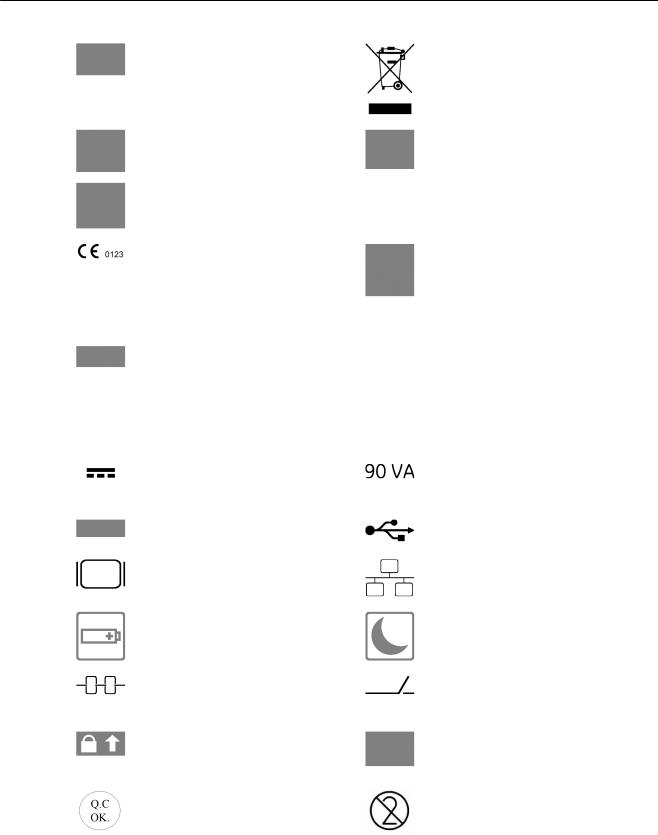
2.1.2 Description of symbols and labels
Some symbols used with electrical medical equipment have been accepted as standard by IEC. They serve for marking connections, accessories, and as warnings.
|
System stand-by switch |
|
Insulated patient application part (Type |
|
|
|
BF) |
|
|
|
|
|
Protection against the effects of |
|
This label is a marker used during |
|
immersion (probes) |
|
manufacturing and has no meaning |
|
|
|
relevant to the usage of the device. |
|
|
|
|
|
Caution, consult accompanying |
|
Consult accompanying documents. This |
|
documents. This symbol advises the user |
|
symbol advises the user to consult the |
|
to consult the accompanying documents |
|
accompanying documents. |
|
for important safety-related information |
|
|
|
such as warnings and pre-cautions that |
|
|
|
cannot be presented on the device itself. |
|
|
|
|
|
|
|
This symbol is followed by the name and |
|
This symbol is followed by the |
|
address of the manufacturer. |
|
manufacturing date in the format YYYY- |
|
|
|
MM. |
|
|
|
|
|
Pictogram on Probe Care Card: |
|
Pictogram on Probe Care Card: |
|
Use care when handling ultrasound |
|
Do not immerse the probe into any liquid |
|
probes and protect the probe head from |
|
beyond the level specified for that probe. |
|
damage. |
|
Refer to the user manual of the |
|
|
|
ultrasound system. |
|
|
|
|
|
Pictogram on Probe Care Card: |
|
Pictogram on Probe Care Card: |
|
Describes precautions necessary to |
|
Describes precautions necessary to |
|
prevent the risk of disease transmission |
|
prevent the risk of injury through electric |
|
or infections. |
|
hazards. |
|
|
|
|
|
This symbol is followed by the serial |
|
Batch or lot number |
|
number of the device. |
|
|
|
|
|
|
Voluson® i Basic User Manual |
|
H48671HD Revision 5 |
2-3 |
Safety
|
Catalog or model number. |
|
Disposal: |
|
|
|
'Disposal' on page 2-15 |
|
|
|
|
|
NRTL Classification Label (old and new |
|
GOST-R Label |
|
version) |
|
|
|
|
|
|
|
CE Conformity mark according to Medical |
|
This product consists of devices that may |
|
Device Directive 93/42/EEC |
|
contain mercury, which must be recycled |
|
0123: Identification number of the notified |
|
or disposed of in accordance with local, |
|
body TÜV SÜD Product Service |
|
state, or country laws. (Within this |
|
|
|
system, the backlight lamps in the |
|
|
|
monitor display, contain mercury.) |
|
|
|
|
|
This symbol indicates PSE rating - |
Green |
Indicates that the power cable is hospital |
|
required for Japanese market |
dot on |
grade. Grounding reliability can only be |
|
|
power |
achieved when the equipment is |
|
|
cable |
connected to an equivalent receptacle |
|
|
plug |
marked “Hospital only” or “Hospital |
|
|
|
grade”. Applicable depending on local |
|
|
|
regulatory requirements. |
|
|
|
|
|
This symbol indicates the voltage that the |
|
This indicates the maximum rated power |
|
device is built for. This device requires |
|
consumption of the system. |
|
direct current. |
|
|
|
|
|
|
|
This label represents the license of the |
|
Indicates a USB connector. |
|
operating system used on this device. |
|
|
|
|
|
|
|
Indicates a monitor connector |
|
Indicates a network connector. |
|
|
|
|
|
Indicates the battery status LED. 'LED |
|
Indicates the power status LED. 'LED |
|
Status Table' on page 3-6 |
|
Status Table' on page 3-6 |
|
|
|
|
|
This symbol indicates the connector for a |
|
Indicates a docking connector for |
|
theft protection lock. |
|
connecting the system to the Voluson |
|
|
|
Station. |
|
|
|
|
|
Indicates the locking mechanism for the |
|
Contains marketing information about |
|
probe connector. |
|
VolusonClub. For more information |
|
|
|
please contact your local sales person. |
|
|
|
|
|
This symbol indicates that the power |
|
Do not reuse! This symbol indicates that |
|
supply has passed the quality check |
|
the item/device is for single use only. |
|
(optional) |
|
|
|
|
|
|
|
Voluson® i Basic User Manual |
2-4 |
H48671HD Revision 5 |

|
|
|
|
Safety |
|
|
|
|
|
|
|
|
|
|
|
|
|
|
|
These symbols indicate that at least one |
|
This symbol indicates that in the United |
|
|
|
of the six hazardous substances of the |
|
States of America, federal law restricts |
|
|
|
China RoHS Labelling Standard is above |
|
this device to sale by or on the order of a |
|
|
|
the RoHS limitation. The number inside |
|
physician. |
|
|
|
the circle is referred to as the |
|
|
|
|
|
Environmental Friendly Use Period |
|
|
|
|
|
(EFUP). It indicates the number of years |
|
|
|
|
|
that the product, under normal use, will |
|
|
|
|
|
remain harmless to health of humans or |
|
|
|
|
|
the environment. |
|
|
|
|
|
EFUP = 10 for Short Use Products |
|
|
|
|
|
EFUP = 10 for Short Use Products |
|
|
|
|
|
|
|
|
|
|
|
Product was refurbished / remanufactured by GE Healthcare Austria GmbH & Co OG |
|
||
|
|
|
|
|
|
2.2 Important Instructions for Safety
FEDERAL LAW RESTRICTS THIS DEVICE TO SALE BY OR ON THE ORDER OF A
PHYSICIAN
The use of the system outside the described conditions or intended use, and disregarding safety related information is considered as abnormal use.
Caution! This machine should be used in compliance with the law. Some jurisdictions restrict certain uses such as gender determination.
Caution:
The quality of the image used for diagnosis is essential:
•Changing the display settings can affect the image quality and compromise the diagnostic quality. The user is responsible to use adequate display settings for achieving appropriate image quality. If in doubt, only the image as displayed on the Voluson® ultrasound system with default display settings is to be used for diagnostic purposes.
•Do not diagnose based on print-outs.
The manual refers to probes that can be connected to the device. It might be possible that some probes are NOT available in some countries.
Some features and options are not available in some countries.
Caution:
Features that facilitate measurements (e.g. SonoAVC follicle, Vocal, SonoNT,...) must be used with extreme care. Such measurements are a suggestion of the system. If in doubt verify the measurement results with manual measurement methods. The user is responsible for the diagnostic interpretation of measurements.
Voluson® i Basic User Manual |
|
H48671HD Revision 5 |
2-5 |

Safety
Caution:
The system provides calculations (e.g estimated fetal weight) and charts based on published scientific literature. The selection of the appropriate chart and clinical interpretation of calculations and charts are the sole responsibility of the user. The user must consider contraindications for the use of a calculation or chart as described in the scientific literature. The diagnosis, decision for further examinations and medical treatment must be performed by qualified personnel following good clinical practice.
This equipment must not be used in oxygen enriched atmosphere or in the presence of inflammable gases (e.g. anesthetic gases) because of explosion hazard!
The system must only be connected to a fully intact mains socket with a grounded guard wire via an appropriate mains cable. The ground wire must never be removed or disconnected.
Ultrasound systems are highly sensitive medical instruments that can easily be damaged by improper handling. Use care when handling and protect from damage also when not in use. DO NOT use a damaged or defective ultrasound system. Failure to follow these precautions can result in serious injury and equipment damage.
No covers or panels must be removed from the system (high-voltage risk). Only GE Healthcare authorized personnel must perform service and repairs. Attempting do-it-yourself repairs invalidate warranty are an infringement to regulations and are inadmissible acc. to IEC 60601-1. For expected lifetime of equipment and probes see Service Manual.
There have been reports of severe allergic reactions to medical devices containing latex (natural rubber). Operators are advised to identify latex-sensitive patients and be prepared to treat allergic reactions promptly. Refer to FDA Medical Alert MDA91-1.
Any power supply of additional equipment has to be confirm with IEC60601-1.
Do not touch the patient and the Signal Input/Output lines at the same time.
Disconnect mains from power supply and remove battery pack to make device electroless.
The use of a protective cover is required when performing surgical procedures to prevent contamination and transfer of infectious material to patients and health care workers when operating the system.
This equipment is not to be used during transportation (e.g. ambulance cars, aircrafts).
Use for diagnostic purposes only!
|
Voluson® i Basic User Manual |
2-6 |
H48671HD Revision 5 |
Safety
Misinterpretation of the ultrasound images can lead to a false diagnosis.
Image quality and penetration depth may be adversely affected when equipment is used on adipose patients.
Using volume, image or video compression methods at higher rates reduces image quality, which can lead to a false diagnosis.
Bright light could impact readability of screen.
Before installing new peripheral devices or other optional items to the Voluson® i, please check the device on cracks or damages. If a device is damaged or has a crack, please contact your local Service or OnlineCenter.
Do not drop the Voluson® i. This may cause major damage to the device.
Do not cover the ventilation holes of the Voluson® i.
Do not use with a defibrillator. This equipment does not have a defibrillator approved applied part.
Only use with provided power supply. 'Power supply' on page 20-4
CAUTION
Laser radiation
Avoid exposure to the beam Class 3B laser product
CAUTION
Class 3B laser radiation When open avoid exposure to the beam
2.3 Electric installation
The system must be exclusively installed in medically used rooms. The equipment conforms with regulations for electrical safety (IEC 60601) and safety class IIa according to the MDD 93/42/EEC regulation for use on human patients. Ultrasound probes are rated Type BF. Local safety regulations may require an additional connection between the potential equilibrium bolt and the building’s grounding system.
Voluson® i Basic User Manual |
|
H48671HD Revision 5 |
2-7 |

Safety
Before switching on the first time, the local mains voltage and frequency are to be checked against the values indicated on the Voluson® i rating plate located on the bottom cover. Only authorized personnel must perform any change to the system. Unauthorized modifications may result in hazardous situations.
The minimum required house installation must have 10A.
2.4Remarks for Safe Use
•Operator profile: Qualified physicians and professional sonographers with at least basic ultrasound knowledge.
•Get acquainted with the transducers and the ultrasound system: read the user manual thoroughly!
•Follow these safety instructions as well as the clinically adopted precautions and measures for hygiene.
•The manufacturer is not liable for damage caused by improper or inexpert use of the device!
•Any ultrasound transducers - irrespective of system and design - are sensitive to shock and shall be treated with care. Pay attention to cracks, which may allow conductive fluids to leak in.
•Authorized personnel shall only perform any type of repair. Never attempt to open a transducer or transducer connector. This leads to a loss of guarantee!
•Do not squeeze, kink, bend or twist probe cables and protect them against mechanical damage.
•The probes must not be exposed to mechanical shock (e.g., by dropping). Any damage caused in this manner invalidates warranty.
•Have the scanner system and the transducers regularly checked (for faulty cables, housing, etc.) by authorized personnel!
•Damage to transducer or cable may lead to a safety hazard, therefore have them repaired immediately!
•Before plugging in or unplugging a transducer, activate the "FREEZE" mode!
•A specialist acquainted with the handling and use of the system shall perform installation and first switch-on and check-up of the system.
•The user must have read and understood the user manual. The system must only be operated by trained and qualified personnel.
•For safety reasons, avoid handling fluids in the vicinity of the system. Fluids leaking into the user interface can damage the Voluson® i.
•Place the unit always on horizontal ground.
•The user manual must always be with the scanner system. It is the user’s duty to ensure this!
•Only probes conforming to type BF requirements may be used with the Voluson® i.
•See the probe’s label. In case of doubt ask authorized service personnel.
•The Voluson® i system has been tested for EMC and is compliant with EN 55011 group 1 class A (CISPR 11 amendment 1) and IEC 60601-1-2.
•Mains power quality should be that of a typical commercial and/or hospital environment. If the user requires continued operation during power mains interruptions, it is recommended that the system be powered from an uninterruptable power source (UPS).
|
Voluson® i Basic User Manual |
2-8 |
H48671HD Revision 5 |
Safety
2.5 Environmental Conditions for Operation
|
For more information see 'Basic Data' on page 20-2. |
Note |
The system is easily portable between rooms. |
|
|
|
Do not operate the system in the vicinity of a source of heat, of strong electric or magnetic |
|
fields (close to a transformer), or near instruments generating high-frequency signals, such as |
|
HF surgery. These can affect the ultrasound images adversely. |
|
|
|
|
|
In the event the equipment has been brought from a cold environment (stock room, airfreight) |
|
into a warm room, allow several hours for temperature balance and passing of condensation |
|
humidity before switching on for the first time. |
|
|
2.6 Instruction for Use
This equipment has been tested and found to comply with the limits for medical devices in IEC 60601-1-2. These limits are designed to provide reasonable protection against harmful interference in a typical medical installation. This equipment generates, uses and can radiate radio frequency energy and, if not installed and used in accordance with the instructions, may cause harmful interference to other devices in the vicinity. However, there is no guarantee that interference will not occur in a particular installation. If this equipment does cause harmful interference to other devices, which can be determined by turning the equipment off and on, the user is encouraged to try to correct the interference by one or more of the following measures:
•Reorient or relocate the device.
•Increase the separation between the equipment.
•Connect the equipment to an outlet on a circuit different from that to which the other device(s) are connected.
•Consult the manufacturer or field service technician for help.
2.7Biopsy Lines
To achieve best possible accuracy of the display of the needle path, the biopsy lines have to be programmed for each transducer. See ' To program a Single Angle Biopsy Line' on page 17-22 and 'To program a Multi Angle Biopsy Line' on page 17-23.
•The biopsy lines must be programmed once by the service personnel or by the user. The procedure must be repeated if probes and /or biopsy guides are exchanged.
•Before performing a biopsy, make sure that the displayed biopsy line coincides with the needle track (check in a bowl filled with approx. 47ºC warm water).
•The needle used for this alignment verification must not be used for the actual procedure.
Always use a straight, new and sterile needle for each biopsy procedure.
Depending on the needle stiffness/thickness and the elasticity and composition of the different tissue-types in the path of the biopsy needle, the actual needle track can deviate from the predicted biopsy line. The biopsy needle might bend and not follow a straight line.
Voluson® i Basic User Manual |
|
H48671HD Revision 5 |
2-9 |

Safety
2.8 Cleaning and Maintenance
Have the system checked and serviced in regular intervals (once per year) by authorized service personnel. In case of total failure first check if main voltage is present. Mentioning any observations or failure symptoms to the service engineers is helpful.
Before cleaning the scanner switch it off. Do not use disinfection spray nor gas disinfection. Electric parts must be protected from drip water. Keep the touch panel screen clean. Dust and grime on the frame can cause irregular function! Check the main cable, transducer cables, plugs and sockets on a regular basis.
No covers or panels must be removed from the system (high-voltage risk). Only GE Healthcare authorized personnel must perform service and repairs. Attempting do-it-yourself repairs invalidate warranty, and are an infringement to regulations and are inadmissible acc. to IEC 60601-1. For expected lifetime of equipment and probes see Service Manual.
The following table provides cleaning instructions for the ultrasound device. Effective cleaning and disinfection is not possible for parts with narrow gaps and holes (e.g. keyboard, trackball,...). It is the responsibility of the user to decide which cleaning and disinfection procedure is necessary to ensure a safe working environment. Electrical contacts and connectors must not be cleaned. Do not use any other cleaning agents than listed in the table below. Do not spray any liquid directly on the system.
Note |
The cleaning instructions apply to Voluson ® i/e, Voluson® Station and Voluson® Dock Cart. |
||||
|
|
|
|
|
|
Component |
When |
How to clean |
|
Cleaning agent |
|
|
|
|
|
|
|
Probe holder |
|
daily or after |
Wipe gently with a damp, |
• |
IPA solution (70% IPA, 30% |
|
|
each |
non-abrasive cloth. |
• |
water) |
|
|
examination |
|
Sani-Cloth Active disinfecting |
|
|
|
|
|
• |
wipes |
|
|
|
|
Acryl des® |
|
Probes |
|
daily or after |
See Probe Care Card and 'Special Handling Instructions' on |
||
|
|
each |
page 18-10 |
|
|
|
|
examination |
|
|
|
|
|
|
|
|
|
User interface |
daily or after |
Wipe gently with a damp, |
• |
Spiritus dilutus (70% ethanol, |
|
|
|
each |
non-abrasive cloth. |
• |
30% water) |
|
|
examination |
|
Acryl des® |
|
Monitor display |
daily or after |
Wipe gently with |
Petroleum benzene |
||
|
|
each |
absorbent cotton or other |
|
|
|
|
examination |
soft material like chamois. |
|
|
|
|
|
|
|
|
Housings |
|
daily or after |
Wipe gently with a damp, |
• |
IPA solution (70% IPA, 30% |
|
|
each |
non-abrasive cloth. |
• |
water) |
|
|
examination |
|
Sani-Cloth Active disinfecting |
|
|
|
|
|
• |
wipes |
|
|
|
|
Acryl des® |
|
Peripherals (e.g. |
Clean according to the instructions of the peripheral manufacturer. |
||||
printers,...) |
|
|
|
|
|
|
|
|
|
|
|
|
Voluson® i Basic User Manual |
2-10 |
H48671HD Revision 5 |
Safety
2.8.1 Safety Test
Scan time limits: According to respective national regulations, and according to the manufacturer recommendations for the medical-technical system.
Range:
a) |
Visual inspection: |
Housing, connection, operating elements, display facilities, labels, |
|
|
accessories, user manual. |
|
|
|
b) |
Functional test: |
Checking of functions (according to user manual), check also |
|
|
modular combinations and common operability of system and |
|
|
accessories. |
|
|
|
c) |
Electric test: |
Checking of the electric safety of system combinations according to |
|
|
EN 62353 or respective national regulations. |
|
|
|
For safety reasons, avoid handling fluids in the vicinity of the system.
Item |
Safety Test |
Notes |
|
|
|
Console Leakage Current |
Annually |
Also after corrective maintenance or as required |
Checks |
|
by your facilities QA program. |
|
|
|
Peripheral Leakage |
Annually |
Also after corrective maintenance or as required |
Current Checks |
|
by your facilities QA program. |
|
|
|
Surface Probe Leakage |
Annually |
Also after corrective maintenance or as required |
Current Checks |
|
by your facilities QA program. |
|
|
|
Endocavity Probe |
Annually |
Also after corrective maintenance or as required |
Leakage Current Checks |
|
by your facilities QA program. |
|
|
|
2.9 Note for the Administration of “Full Backup” Data
All settings and patient data created since last full backup are NOT backed-up! It is highly recommended to create a full backup of settings and patient data regularly.
When the Full Backup is stored on a network drive, it may be desirable to move the data (e.g., for backup or maintenance). For further details review: 'Backup' on page 16-16
The directory structure of the full backup data is as follows:
Voluson® i Basic User Manual |
|
H48671HD Revision 5 |
2-11 |

Safety
Every “Full Backup” resides in a sub-folder of the main “fullbackup”-folder found at the root of the drive. For example: Z:\fullbackup.
The sub-folders have the names fbX where X is a number (e.g., Z:\fullbackup\fb1). The data resides within a directory structure within these sub-folders. It is possible to move the fbX subfolders, even leaving gaps in the numeration sequence. However, NO change MUST be made to the contents of the fbX folders itself, otherwise the backup data cannot be restored!
2.10 Manufacturer Responsibility
The manufacturer, assembler, importer or installer considers himself/herself responsible regarding safety, reliability and performance of the instrument under the following conditions:
•when assembling the system, when adding options, when new settings or modifications or repairs were performed by personnel authorized by him/her,
•also that the local electric installation complies to the national regulations, and that the equipment is only used according to the User Manual.
2.11Service Documents
The Service Manual supplies block diagrams, lists of spare parts, descriptions, adjustment instructions or similar information which help adequately qualified technical personnel in repairing those parts of the instrument which have been defined repairable by the manufacturer. If requested the manufacturer will supply the service manual to authorized technical personnel.
2.11.1 Service Software – Remote Access
By using the remote access feature, a GE field engineer can access the ultrasound system via a modem connection. The field engineers are required to announce every remote connection to a system previously by calling the affected site.
|
Disruptive Mode: |
|
If the field engineer requires unrestricted access to the ultrasound system the field engineer |
|
requests for disruptive mode on the system. A message appears on the screen asking for |
|
permission to switch to disruptive mode: |
|
GE Service is requesting permission to diagnose the system remotely.Normal system |
|
operations might be disturbed during this period.Click on YES to allow GE Service to continue |
|
system diagnostics. |
|
If disruptive mode is accepted, work on the system can be disturbed severely. Therefore, it is |
|
not allowed to perform an exam or make a diagnosis using the ultrasound system while being |
|
in disruptive mode. |
Note |
A remote connection can affect the system’s performance (e.g.,in 3D/4D or Doppler mode). |
|
Therefore, it is recommended to cease work on the system as soon as the field engineer |
|
contacts the site and announces the remote connection. |
|
Network Security: |
|
The remote access features enables, after checkout has been performed, network services |
|
like ftp or telnet on the ultrasound system. Therefore, it is advisable to restrict network access |
|
to system for unauthorized personnel. It is strongly recommended to use a firewall to restrict |
|
Voluson® i Basic User Manual |
2-12 |
H48671HD Revision 5 |

Safety
network access from and to an ultrasound system with the remote access feature installed. Other precautions like a secure network segment are encouraged.
For Ethernet connection, a separation device has to be used.
2.12 Bioeffects and Safety of Ultrasound Scans
When ultrasound waves travel through tissue, there is a certain risk for damage. There has been a lot of research on the impact that high frequency waves can have on different kinds of tissues under defined conditions and “There is, to date, no evidence that diagnostic ultrasound has produced any harm to humans – including the developing fetus.” (Guidelines for the safe use of diagnostic ultrasound equipment, Safety Group of the British Medical Ultrasound Society 2010).
Physiological effects due to ultrasound are generally assumed to be deterministic and only occur above a certain threshold in contrast to ionizing radiation, which causes effects accidentally. Thus ultrasound examinations can be held very safe if certain proceedings are followed. It is therefore recommended to read the following sections and study the cited literature.
2.12.1 Prudent Use – ALARA Principle
In spite of the relatively low risk of ultrasound scans compared to other imaging techniques, the operator shall choose the exposure level with caution to minimize the risk of bioeffects.
“A fundamental approach to the safe use of diagnostic ultrasound is to use the lowest output power and the shortest scan time consistent with acquiring the required diagnostic information. This is the ALARA principle (i.e. As Low As Reasonably Achievable). It is acknowledged that in some situations it is reasonable to use higher output or longer examination times than in others: for example, the risks of missing a fetal anomaly must be weighed against the risk of harm from potential bioeffects. Consequently, it is essential for operators of ultrasound scanners to be properly trained and fully informed when making decisions of this nature.” (Guidelines for the safe use of diagnostic ultrasound equipment, Safety Group of the British Medical Ultrasound Society 2010)
Special care regarding ALARA should be taken with obstetric examinations as any potential bioeffects are likely to be of greatest significance in the embryo or fetus.
It is strongly recommended to consider ALARA when undertaking ultrasound scans.
2.12.2Bioeffects
•Thermal effects refer to heating of soft tissue and bone
The thermal indices TIs (soft tissue), TIb (bone near focus) and TIc (bone near surface) were introduced to provide the operator a relative potential for a tissue temperature rise. According to the Standard for Real-time Display of Thermal and Mechanical Acoustic Output Indices on Diagnostic Ultrasound Equipment (2004) those thermal indices shall be displayed by this ultrasound console. It should be noted that a TI of 1 does not necessarily mean that tissues being scanned will increase in temperature by 1˚C – almost every scanning situation departs from the assumed model conditions, such as tissue type, blood perfusion, mode of operation and actual exposure time of the scanned area. However, the thermal indices provide information regarding the possible increase in the risk of potential thermal bioeffects and it provides a relative magnitude that can be
Voluson® i Basic User Manual |
|
H48671HD Revision 5 |
2-13 |

Safety
used to implement ALARA. In addition to tissue heating due to the generated ultrasound field, the temperature of the probe head itself can also increase during the examination. The operator shall be aware, that in the tissue region near the ultrasonic transducer, there will be a superposition with the heating due to the ultrasound field, which is not considered by the TI values.
•Nonthermal effects refer to mechanical phenomena such as cavitation
Nonthermal bioeffects are caused by the interaction of ultrasound fields with very small pockets of gas (stabilized gas bodies), i.e. the generation, growth, vibration and possible collapse of microbubbles within the tissue. This behavior is referred to as cavitation (Medical Ultrasound Safety, 2nd Edition, AIUM 2009/American Institute of Ultrasound in Medicine Consensus Report on Potential Bioeffects of Diagnostic Ultrasound, AIUM 2008/Guidelines for the safe use of diagnostic ultrasound equipment, Safety Group of the British Medical Ultrasound Society 2010). The potential of cavitation increases with the rarefactional peak pressure but decreases with the pulse frequency. Therefore the Mechanical Index MI was introduced to take account of both the pressure and the frequency. The higher the MI the greater is the risk of nonthermal bioeffects.
2.12.3Regulated Parameters
Relevant parameters having physiological effects (For more information see 'Bioeffects' on page 2-13.) are regulated according to FDA and IEC guidelines and standards. These parameters are
Parameter |
Meaning |
Limit |
Displayed |
|
|
|
|
MI |
Mechanical Index |
1.9 |
Yes |
|
|
|
|
TIs, TIb, TIc |
Thermal Indices TI – one of the |
6 |
Yes |
|
following values can be displayed: |
|
|
|
TIs: soft tissues |
|
|
|
TIb: bone in focal region |
|
|
|
TIc: bone at surface (e.g. cranial) |
|
|
|
|
|
|
Ispta.3 |
Averaged intensity at spatial peak |
720 mW/cm2 |
No |
|
with a derating of 0.3dB/(cm MHz) |
|
|
|
|
|
|
T |
Temperature at the patient’s side of |
43˚C/50˚C |
No |
|
the probe – lower limit during patient |
(109.4˚F/122˚F) |
|
|
contact, higher limit for rest position |
|
|
|
|
|
|
2.12.4 Interpretation of displayed parameters MI and TI
During obstetric examinations these displayed values shall be observed very critically, because there may be conditions that are potentially hazardous even below the regulatory limits.
Some guidelines recommend that embryonic and fetal in situ temperatures of 41˚C (4˚C above normal temperature) should be limited in time by 5 min or less. Thus, for a reasonable safety margin, TI values above 1 should be avoided. Additional factors, like fever of the mother, are again reasons to keep the TI values as low as possible on the one hand, and go only as high as necessary to achieve the desired clinical results ('Prudent Use – ALARA Principle' on page 2-13).
The mechanical index, which indicates the risk of cavitation, becomes important at the interface between gas and soft tissue (nonfetal lung and bowel), but also with the use of gas body contrast agents. Often an MI value of 0.4 or less is suggested for examinations of tissue
|
Voluson® i Basic User Manual |
2-14 |
H48671HD Revision 5 |

Safety
containing stabilized gas bodies. This value arises from operating experience and is not confirmed.
Some examples where the MI and TI, respectively, are more or less important are shown in the following table according to Particular requirements for the basic safety and essential performance of ultrasonic medical diagnostic and monitoring equipment, IEC 60601-2-37 2nd Edition, 2007, Annex CC.
|
Of greater importance |
Of less importance |
|
|
|
MI – |
With contrast agents |
In the absence of gas bodies, i.e. most |
Mechanical |
Cardiac scanning (lung exposure) |
tissue scanning |
Index |
Abdominal scanning (bowel gas) |
|
|
|
|
|
|
|
TI – |
1st trimester scanning |
Well perfused tissue, i.e. liver, spleen |
Thermal |
Fetal skull and spine |
Cardiac scanning |
Indices |
Neonatal head |
Vascular scanning |
|
||
|
Patient with fever |
|
|
Poorly perfused tissue |
|
|
Scanning near ribs or bone: TIb |
|
|
|
|
Further information can be retrieved from Bioeffects & Safety of Diagnostic Ultrasound, AIUM, 1993 and Evaluation of Research Reports: Ultrasound Bioeffects Literature Reviews (1992-2003).
2.12.5 Reporting Tables
Acoustic output reporting tables according to the below cited standards are provided in the
Basic Service Manual.
Particular requirements for the basic safety and essential performance of ultrasonic medical diagnostic and monitoring equipment, IEC 60601-2-37 2nd Edition, 2007.
Information for Manufacturers Seeking Marketing Clearance of Diagnostic Ultrasound Systems and transducers, FDA Guidance, 2008.
Ultrasonics - Field characterization - Test methods for the determination of thermal and mechanical indices related to medical diagnostic ultrasonic fields, IEC 62359 1st Edition, 2005.
2.13 Disposal
This symbol indicates that the waste of electrical and electronic equipment must not be disposed as unsorted municipal waste and must be collected separately. Please contact the manufacturer or an other authorized disposal company to decommission your equipment according to local regulations.
2.13.1 Battery disposal
Voluson® i Basic User Manual |
|
H48671HD Revision 5 |
2-15 |

Safety
Lithium battery included with this device. Do not puncture, mutilate or dispose of battery in fire. Replace only with same type recommended by the manufacturer. Dispose of used battery according to manufacturers instructions and in accordance with your local regulations.
2.14 Guidance and manufacturer´s declaration
Guidance and manufacturer´s declaration - electromagnetic emissions
The Voluson® i is intended for use in electromagnetic environment specified below. The customer or the user of the Voluson® i should assure that it is used in such an environment.
Emission test |
Compliance |
Electromagnetic environment - guidance |
|
|
|
|
|
RF emissions - CISPR 11 |
Group 1 |
The Voluson® i uses RF energy only for its internal |
|
|
|
function. Therefore, its RF emissions are very low and |
|
|
|
are not likely to cause any interference in nearby |
|
|
|
electronic equipment. |
|
|
|
|
|
RF emissions - CISPR 11 |
Class A |
The Voluson® i is suitable for use in all establishments |
|
|
|
(i.e. hospitals, doctors practice etc.) other than |
|
Harmonic emissions IEC |
Class A |
||
domestic. The Voluson® i is intended for professional |
|||
61000-3-2 |
|
||
|
use only. |
||
|
|
||
Voltage fluctuations/ |
Complies |
|
|
flicker emissions IEC |
|
|
|
61000-3-3 |
|
|
|
|
|
|
Guidance and manufacturer´s declaration - electromagnetic immunity
The Voluson® i is intended for use in electromagnetic environment specified below. The customer or the user of the Voluson® i should assure that it is used in such an environment.
Immunity test |
IEC 60601 test level |
Compliance level |
Electromagnetic |
|
|
|
environmentguidance |
|
|
|
|
Electrostatic discharge |
± 2,4,6 kV contact |
± 2,4,6 kV contact |
Floors should be wood, |
(ESD) IEC 61000-4-2 |
± 2,4,8 kV air |
± 2,4,8 kV air |
concrete or ceramic tile. If |
|
floors are covered with |
||
|
|
|
|
|
|
|
synthetic material, the |
|
|
|
relative humidity should be |
|
|
|
at least 30 %. |
|
|
|
|
Electrical fast transient/ |
± 2kV for power supply |
± 2kV for power supply |
Mains power quality |
burst IEC 61000-4-4 |
lines |
lines |
should be that of a typical |
|
±1kV for input/output lines |
±1kV for input/output lines |
commercial or hospital |
|
environment. |
||
|
|
|
|
Surge IEC 61000-4-5 |
± 1kV differential mode |
± 1kV differential mode |
Mains power quality |
|
± 2kV common mode |
± 2kV common mode |
should be that of a typical |
|
commercial or hospital |
||
|
|
|
|
|
|
|
environment. |
|
|
|
|
|
Voluson® i Basic User Manual |
2-16 |
H48671HD Revision 5 |
Loading...