


 Loading...
g
GE Medical Systems
Technical
Publications
Vivid 7/EchoPAC PC
Dimension - version 7.x.x
0470
4D and Multi-plane Imaging
GEVU #: FD092081
GEVU Rev. 01
MHLW No: 21300BZY00416000
Operating Documentation
Copyright © 2007 By General Electric Co.

g
GE Medical Systems
MANUAL STATUS FD092081-01 01/08/2007
© GE Medical Systems. All rights reserved. No part of this manual may be reproduced, stored in a retrieval system, or transmitted, in any form or by any means, electronic, mechanical, photocopying, recording, or otherwise, without the prior written permission of GE Medical Systems.
COMPANY DATA |
GE VINGMED ULTRASOUND A/S |
|
Strandpromenaden 45, N-3191 Horten, Norway |
|
Tel.: (+47) 3302 1100 Fax: (+47) 3302 1350 |

|
Table of Contents |
Table of Contents |
|
Table of Contents |
|
Introduction |
|
4D imaging ..................................................................................... |
1 |
Multi-plane Imaging....................................................................... |
2 |
Measurement and analysis........................................................... |
2 |
Multi-plane stress echo................................................................. |
2 |
Remark concerning the 3V probe ................................................ |
2 |
Important........................................................................................ |
3 |
Conventions used in this manual ................................................ |
4 |
Chapter 1 |
|
4D Imaging |
|
Introduction.................................................................................... |
6 |
4D mode overview - Vivid 7 .......................................................... |
7 |
Volume rendering mode screen............................................ |
7 |
Slice mode screen ................................................................ |
8 |
4D mode controls.................................................................. |
9 |
Assigned rotaries and keys................................................. |
10 |
4D mode assigned controls ................................................ |
11 |
Additional 4D mode assigned controls ............................... |
14 |
Soft menu controls.............................................................. |
16 |
Trackball controls................................................................ |
17 |
Display controls .................................................................. |
19 |
Using 4D mode - Vivid 7.............................................................. |
21 |
Parasternal view acquisition ............................................... |
21 |
Apical view acquisition........................................................ |
22 |
Full volume acquisition ....................................................... |
23 |
Rotating/Translating the 4D image ..................................... |
25 |
Zooming.............................................................................. |
26 |
Cropping ............................................................................. |
26 |
9 Slice................................................................................. |
29 |
4D mode overview - EchoPAC PC ............................................. |
32 |
4D/Multiplane Imaging User's Manual |
1 |
FD092081-01 |
|

Table of Contents
Volume rendering mode screen .......................................... |
32 |
Slice mode screen............................................................... |
33 |
4D mode control panel ........................................................ |
34 |
Display controls................................................................... |
36 |
Cropping.............................................................................. |
37 |
Working with 4D acquisitions - EchoPAC PC ........................... |
39 |
9 Slice.................................................................................. |
39 |
4D LV Volume application........................................................... |
41 |
Starting the 4D LV Volume application — Vivid 7 ............... |
41 |
Starting the 4D LV Volume application — EchoPAC PC .... |
41 |
Chapter 2 |
|
4D Color Flow Imaging |
|
Introduction .................................................................................. |
44 |
4D Color Flow mode overview - Vivid 7 ..................................... |
45 |
Color Flow Volume rendering mode screen ........................ |
45 |
Color Flow Slice mode screen............................................. |
46 |
4D Color Flow mode controls .............................................. |
47 |
Assigned rotaries and keys ................................................. |
48 |
4D Color Flow mode assigned controls............................... |
49 |
Additional 4D mode assigned controls ................................ |
50 |
Soft menu controls .............................................................. |
51 |
Trackball controls ................................................................ |
52 |
Display controls................................................................... |
52 |
Using 4D Color Flow mode - Vivid 7........................................... |
54 |
Real time 4D Color flow acquisition..................................... |
54 |
Full volume Color Flow acquisition...................................... |
55 |
6 Slice.................................................................................. |
57 |
4D Color Flow mode overview - EchoPAC PC .......................... |
60 |
Volume rendering mode screen .......................................... |
60 |
Slice mode screen............................................................... |
61 |
4D mode control panel ........................................................ |
62 |
Chapter 3 |
|
Multi-plane imaging |
|
Introduction .................................................................................. |
66 |
2 |
4D/Multiplane Imaging User's Manual |
|
FD092081-01 |

Table of Contents |
|
Multi-plane mode overview - Vivid 7.......................................... |
67 |
Bi-plane mode screen......................................................... |
67 |
Tri-plane mode screen........................................................ |
68 |
Multi-plane mode controls................................................... |
69 |
Using Multi-plane mode imaging - Vivid 7 ................................ |
77 |
Scan plane rotation............................................................. |
78 |
Tilting scan plane 2............................................................. |
78 |
Zooming.............................................................................. |
79 |
Multi-plane mode overview - EchoPAC PC ............................... |
82 |
Bi-plane mode screen......................................................... |
82 |
Tri-plane mode screen........................................................ |
83 |
The multi-plane control panel ............................................. |
84 |
Working with multi-plane acquisitions - EchoPAC PC ............ |
85 |
Chapter 4 |
|
Measurements and Analysis |
|
Introduction.................................................................................. |
88 |
Left ventricular volume measurements..................................... |
89 |
Tri-plane acquisition............................................................ |
89 |
Full volume acquisition ....................................................... |
92 |
Rotation of the Volume reconstruction................................ |
93 |
Bi-plane acquisition............................................................. |
94 |
TSI surface model........................................................................ |
96 |
To edit the sampling path ................................................... |
97 |
Quantitative analysis................................................................... |
98 |
Starting Quantitative analysis from a multi-plane |
|
acquisition........................................................................... |
98 |
Chapter 5 |
|
Multi-plane Stress Echo |
|
Introduction................................................................................ |
102 |
Creating a Multi-plane stress test template ............................ |
103 |
Launching the Template editor ......................................... |
104 |
Stress Template setup...................................................... |
104 |
Stress test acquisition .............................................................. |
106 |
Baseline acquisitions ........................................................ |
106 |
4D/Multiplane Imaging User's Manual |
3 |
FD092081-01 |
|

Table of Contents
Low dose and Peak dose level acquisitions...................... |
109 |
Image analysis............................................................................ |
112 |
Index |
|
4 |
4D/Multiplane Imaging User's Manual |
|
FD092081-01 |
Introduction
Introduction
This user manual describes the 4D and Multi-plane Imaging applications for the Vivid 7 Dimension and
EchoPAC PC Dimension.
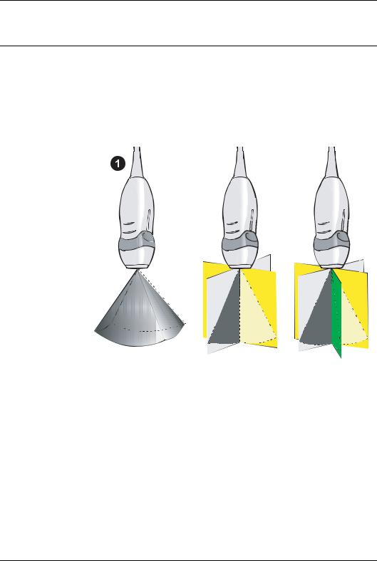
The 2D matrix probe 3V enables real time volume rendering, simultaneous bi-plane or tri-plane data acquisition (multi-plane acquisition).
1.Real time Volume acquisition (4D imaging)
2.Real time Bi-plane acquisition
3.Real time Tri-plane acquisition
4D imaging
4D imaging enables real time acquisition and rendering of volume ultrasound data. Free rotation of the 3-dimensional image combined with the zoom function and 4D image optimization controls enhance spatial understanding of the anatomical structure and function of the heart.
4D imaging is available in combination with B-Mode only.
4D/Multiplane Imaging User's Manual |
1 |
FD092081-01 |
|

Introduction
Multi-plane Imaging
Multi-plane imaging displays two (Bi-plane) or three (Tri-plane) rotated scan planes acquired simultaneously. Free rotation, tilting (in Bi-plane) of the scan planes and zoom enable the investigation of anatomical structures from different angles.
Multi-plane imaging is available from B-Mode, Color flow mode and TVI related modes.
If not otherwise specified, the term multi-plane means either
Bi-plane or Tri-plane.
Measurement and analysis
All cardiac measurements available in B mode are also available in 4D and Multi-plane.
The 4D and Multi-plane modes enable the creation of a left ventricular volume reconstruction based on contours drawn from three cross sections at both end-systole and end-diastole with calculation of end-systolic and end-diastolic volumes and ejection fraction.
Multi-plane stress echo
Combined with specially designed Stress echo protocols, Multi-plane mode enables faster stress tests as several views can be acquired simultaneously.
Remark concerning the 3V probe
The 3V probe temperature will increase during extensive use, due to heating from the probe electronics. If the probe reaches its temperature limit, this will be detected by the system and scanning will stop. Currently, this limit is set to 42.3 degrees Celsius, which complies with regulatory instructions relating to patient comfort and safety. This is reported with a dialog box and the user has to wait until the temperature is below acceptable limits before scanning can continue. This does not in any way indicate probe malfunction. The user has to unfreeze to start scanning again.
In order to reduce the chance for full freeze due to heating, the system will reduce power slightly in a temperature interval just
2 |
4D/Multiplane Imaging User's Manual |
|
FD092081-01 |

Introduction
below the full freeze limit. Changes to the power level are reported in the status bar as Setting power level down and
Setting power level up.
The recommended use of this probe for live 4D and full volume 4D scanning is to enter full freeze whenever the probe is not used for imaging. For other modalities no special actions are required.
Important
Read and understand all instructions in the Vivid 7 and EchoPAC PC User manuals before attempting to use the devices.
4D/Multiplane Imaging User's Manual |
3 |
FD092081-01 |
|

Introduction
Conventions used in this manual
|
Keys and button, on the control panel or alphanumeric |
||
|
keyboard are indicated by over and underlined text (ex. |
2D |
|
|
refers to the 2D mode key) |
||
|
Bold type, describes button names on the screen. |
||
|
Italic type: describes program windows, screens and dialogue |
||
|
boxes. |
||
|
Icons, highlight safety issues as follow: |
||
|
Indicates that a specific hazard exists that, given inappropriate |
||
DANGER |
conditions or actions, will cause: |
||
• Severe or fatal personal injury |
|||
|
• Substantial property damage |
||
|
Indicates that a specific hazard exists that, given inappropriate |
||
WARNING |
conditions or actions, will cause: |
||
• Severe personal injury |
|||
|
• Substantial property damage |
||
|
Indicates that a potential hazard may exist that, given |
||
|
inappropriate conditions or actions, can cause: |
||
CAUTION |
• Minor injury |
||
|
• Property damage |
||
4 |
4D/Multiplane Imaging User's Manual |
|
FD092081-01 |
4D Imaging
Chapter 1
4D Imaging
• Introduction ................................................................................... |
...... 6 |
• 4D mode overview - Vivid 7 .......................................................... ...... |
7 |
• Volume rendering mode screen ................................................... |
7 |
• Slice mode screen ........................................................................ |
8 |
• 4D mode controls ......................................................................... |
9 |
• Using 4D mode - Vivid 7 ............................................................... .... |
21 |
• Parasternal view acquisition ....................................................... |
21 |
• Apical view acquisition ............................................................... |
22 |
• Full volume acquisition ............................................................... |
23 |
• Rotating/Translating the 4D image ............................................. |
25 |
• Zooming ..................................................................................... |
26 |
• Cropping ..................................................................................... |
26 |
• 9 Slice ........................................................................................ |
29 |
• 4D mode overview - EchoPAC PC ............................................... .... |
32 |
• Volume rendering mode screen ................................................. |
32 |
• Slice mode screen ...................................................................... |
33 |
• 4D mode control panel ............................................................... |
34 |
• Display controls .......................................................................... |
36 |
• Working with 4D acquisitions - EchoPAC PC ............................ .... |
39 |
• 9 Slice ........................................................................................ |
39 |
• 4D LV Volume application ............................................................ .... |
41 |
• Starting the 4D LV Volume application — EchoPAC PC ........... |
41 |
4D/Multiplane Imaging User's Manual |
5 |
FD092081-01 |
|

4D Imaging
Introduction
The 3V probe enables real time acquisition of volume ultrasound data. Free rotation of the three-dimensional image combined with zooming and 4D image optimization controls enhance spatial understanding of the anatomical structure and function of the heart.
Two display modes are available, Volume rendering mode for three dimensional scanning and Slice mode for measurements and volume reconstruction purpose.
4D imaging is available from B mode only.
6 |
4D/Multiplane Imaging User's Manual |
|
FD092081-01 |
4D Imaging
4D mode overview - Vivid 7
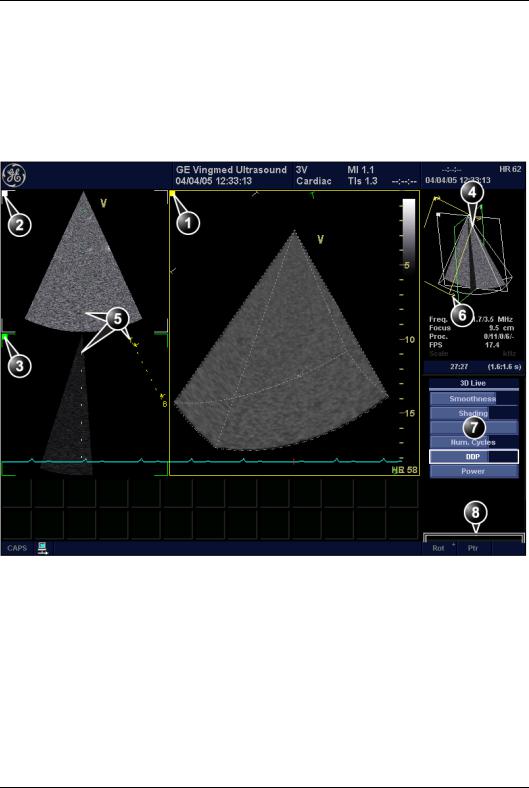
Volume rendering mode screen
The Volume rendering mode displays a volume rendering and 2D images from two perpendicular cut-planes.
1.Volume rendering display from cut-plane 1 (yellow). The volume rendering may be adjusted by rotating and translating the cut-plane 1.
2.Cut-plane 2 (white): 2D image in the azimuth plane.
3.Cut-plane 3 (green): 2D image in the elevation plane.
4.Orientation window: displays a three-dimensional model with cut-planes position and orientation.
5.Color coded cut-plane markers indicate the other cut-planes position relative to the displayed cut-plane.
6.View direction marker.
7.Soft menu controls (see page 16)
8.Trackball functions (see page 17)
Figure 1-1: The 4D screen (Volume rendering)
4D/Multiplane Imaging User's Manual |
7 |
FD092081-01 |
|
4D Imaging
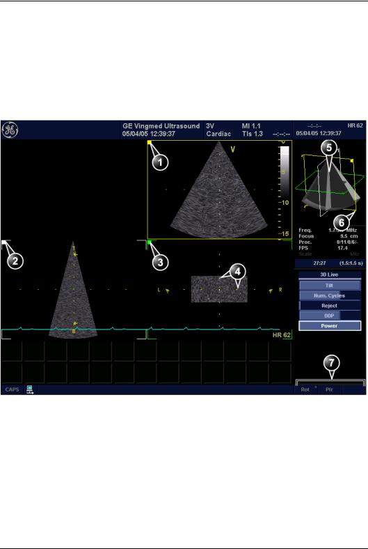
Slice mode screen
The Slice mode displays three cut-planes. The cut-planes can be rotated and translated independently of each other. This mode is use to perform measurements and volume reconstruction based on contour traces done on several cut-planes.
1.Cut-plane 1 (yellow)
2.Cut-plane 2 (white)
3.Cut-plane 3 (green)
4.Color coded cut-plane markers indicate the position of the other cut-planes relative to the displayed cut-plane.
5.Orientation window: displays a three-dimensional model with cut-planes position.
6.View direction marker.
7.Trackball functions (see page 17)
Figure 1-2: The 4D screen (Slice mode)
8 |
4D/Multiplane Imaging User's Manual |
|
FD092081-01 |

4D Imaging
4D mode controls
 3
3
 4
4
|
ck |
ll |
a |
a |
|
Tr |
|
B |
Width
Update
Menu
/
1.4D key
2.Multiplane key (see page 65)
3.Assigned 4D rotaries: see next page.
4.Assigned 4D keys: see next page.
5.Zoom/HR Zoom (see page 20)
6.Layout (see page 19): toggles the display between:
•Multi screen with volume/slice
•Single screen volume/slice
7.Soft menu
8.Trackball (see page 17)
•Rotate/translate volume rendering or selected cut-plane (Slice mode)
•Scroll through the cineloop
9.Clear: resets the orientation to default positions.
10.Angle: predefined orientations optimized for volume rendering.
11.4D Gain
12.2D Gain
Figure 1-3: The 4D controls on the control panel
4D/Multiplane Imaging User's Manual |
9 |
FD092081-01 |
|

4D Imaging
Assigned rotaries and keys
Volume rendering assigned controls |
|
|
|
|||
1. |
Assigned rotaries |
2. |
Assigned keys |
|||
|
• Width |
|
• Slice R |
|||
|
• Frequency |
|
• Front/Back |
|||
|
• Focus position |
|
• Crop (in Freeze only) R |
|||
|
• Volume size |
|
• Box (in Freeze only) R |
|||
|
|
|
menu |
|
• Cineloop (in Freeze only) R |
|
|
MORE |
|
||||
|
• Translate R |
|
• Full volume |
|||
|
|
• 4D Colorize R |
||||
|
|
|
|
|
||
|
|
|
|
|
• 9 Slice (in Full volume Freeze only) R |
|
|
|
|
|
|
|
menu |
|
|
|
|
|
MORE |
|
|
|
|
|
|
• Up/Down R |
|
|
|
|
|
|
• Flip R |
|
|
|
|
|
|
• Orientation window R |
|
|
|
|
|
|
• Cine rotate (in Freeze only) R |
|
Slice mode assigned controls |
|
|
|
|||
1. |
Assigned rotaries |
2. |
Assigned keys |
|||
|
• Width |
|
• Slice exit R |
|||
|
• Rotate R |
|
• Reference plane R |
|||
|
• Translate (in Freeze only) R |
|
• Cineloop (in Freeze only) R |
|||
|
• Focus position |
|
|
menu |
||
|
|
MORE |
||||
|
• Volume size |
|
• Up/Down R |
|||
|
MORE |
menu |
|
• Orientation window R |
||
• Frequency
Controls marked with R are also available in cine replay.
Figure 1-4: Volume rendering and Slice mode assigned controls
10 |
4D/Multiplane Imaging User's Manual |
|
FD092081-01 |
4D Imaging
4D mode assigned controls
This section describes only the 4D mode controls. The scanning mode controls are described in the system User manual.
Width
(Volume rendering and Slice mode, Live)
Controls both elevation and azimuth widths, an increase of the elevation width results in a decrease of the azimuth width.
Volume size
(Volume rendering and Slice mode, Live)
Controls the size of the volume. Adjusting the volume size may affect the volume rate.
Rotate
(Slice mode, Live and Replay)
Rotate the selected cut-plane around the z-axis (see
Figure 1-5).
1. Rotate control
Figure 1-5: Cut-plane rotation around the z-axis
Slice/Slice exit
(Volume rendering and Slice mode, Live and Replay)
Toggles the display between Volume rendering (Figure 1-1) and Slice mode (Figure 1-2).
4D/Multiplane Imaging User's Manual |
11 |
FD092081-01 |
|
4D Imaging
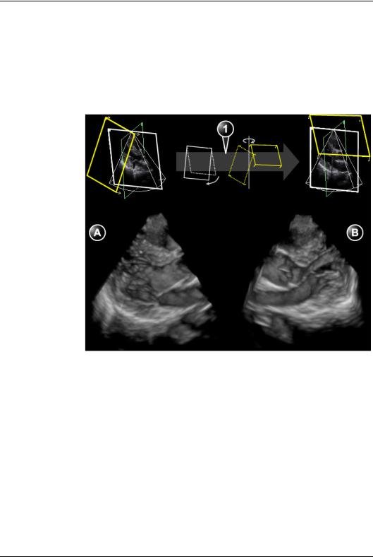
Front/Back
(Volume rendering, Live and Replay)
Tilts the volume in the elevation direction and rotates the view position in one operation. FRONT/BACK enables volume rendering display from different angles (Figure 1-6).
1. Front/Back: Volume tilt and View position rotation
A.Volume tilted to the left, view position looking towards the anterior wall.
B.Volume tilted to the right, view position looking towards the inferior wall.
Figure 1-6: Front/Back control on a PLAX volume
Reference plane
(Slice mode, Live and Replay)
Toggles the cut-plane selection between cut-plane 1, 2 or 3.
Crop (Free cropping)
(Volume rendering, Freeze and Replay)
12 |
4D/Multiplane Imaging User's Manual |
|
FD092081-01 |
4D Imaging
Removes all data up front of the active cut-plane. Cropping can be applied on several parts of the volume by rotating/translating the active cut-plane (see page 26).
Box (Box cropping)
(Volume rendering, Freeze and Replay)
Removes all data around a user-adjustable box (see page 27).
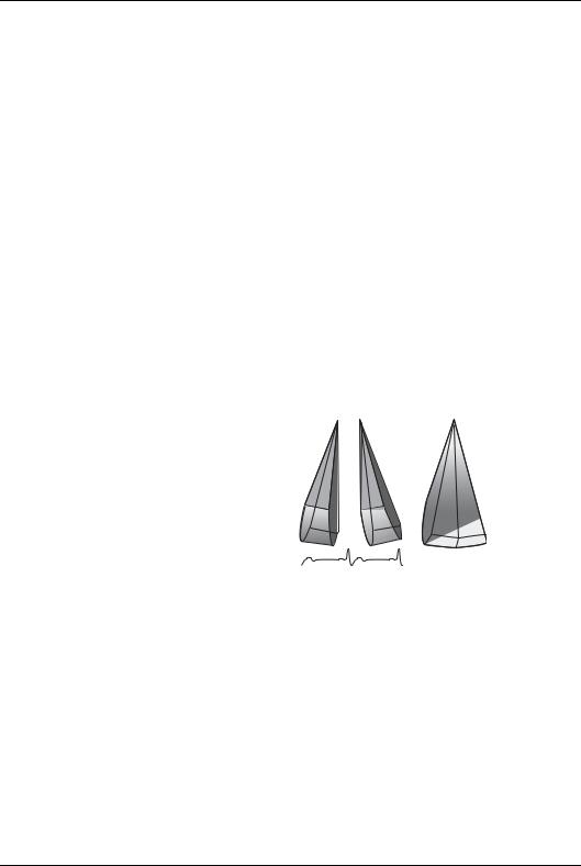
Full volume
(Volume rendering, Live)
Activates the ECG triggered sub-volume acquisition. This technique enables the acquisition of a larger volume without compromising the resolution, by combining several sub-volumes acquired over two to six heart cycles (see Figure 1-7). When acquisition is done for the number of heart cycles set, the process is repeated replacing the oldest sub-volumes.
+=
Figure 1-7: ECG triggered volume acquisition (two heart cycles)
4D Colorize
(Volume rendering, Live and Replay)
Adjusts the volume rendering color from a color map menu.
Depth encoded color maps
From this menu the user can also select a depth encoded color map. These color maps use colors to improve the perception of depth. Selecting the bronze/blue color map will display structures that are close to the view plane with a bronze color. Structures that are farther behind will be colored with a gray
4D/Multiplane Imaging User's Manual |
13 |
FD092081-01 |
|

4D Imaging
color, while the structures that are farthest behind will be colored in blue. Very bright colors are almost white, independent of the depth.
Stereo vision
4D Stereo vision is a display technique that enhances the perception of depth in 3D renderings. This is achieved by mixing two different volume renderings with slightly separated viewing angles and presenting them separately to the user’s left and right eyes. This feature requires the use of anaglyph stereo glasses (glasses with one red and one cyan lens).
Normally you should be able to see the stereoscopic effect after a few seconds. The effect may gradually improve after a while. If you are already wearing glasses or lenses you should not take them off, since the stereo effect then may be greatly reduced.
Note: Not all users may be able to perceive depth using stereoscopic display techniques.
Additional 4D mode assigned controls
The following controls are available after pressing MORE.
Up/Down
(Volume rendering and Slice mode, Live and Replay) Flips the volume 180 degrees.
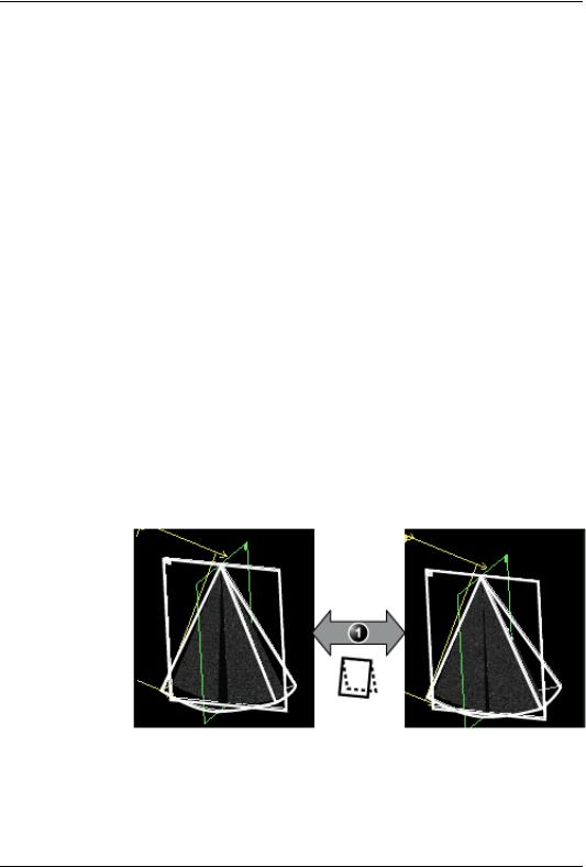
Flip
(Volume rendering, Live and Replay) Flips the view position (Figure 1-8).
14 |
4D/Multiplane Imaging User's Manual |
|
FD092081-01 |
4D Imaging
1. Flip control
A.View position looking downward
B.View position looking upward
Figure 1-8: Flip control
Orientation window
(Volume rendering and Slice mode, Live and Replay) Shows/hides the Orientation window.
Cine rotate
(Volume rendering, Replay)
Rotates back and forth the volume rendering.
4D/Multiplane Imaging User's Manual |
15 |
FD092081-01 |
|
4D Imaging
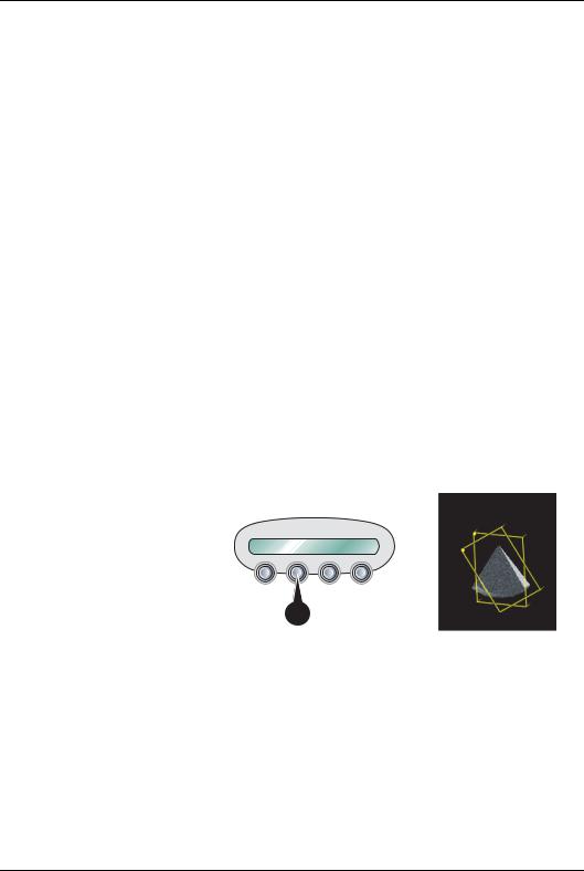
Soft menu controls
Soft menu controls are related to image quality adjustment. These controls are accessed using the 4-way rocker on the control panel. Only the 4D controls are described in this section, refer to the system user manual for general imaging controls.
Smoothness
(Volume rendering, Live and Replay)
Affects continuity of structures and image noise. Too much smoothness will blur the image, too little will leave too much noise.
Shading
(Volume rendering, Live and Replay)
Adjusts the shading effect on the image. Shading may improve three dimensional perception.
Tilt
(Volume rendering, Live)
Tilts the volume in the elevation direction.
1. Tilt control: volume tilting in the elevation direction
Figure 1-9: Tilt control
16 |
4D/Multiplane Imaging User's Manual |
|
FD092081-01 |

4D Imaging
Number of Cycles
(Volume rendering, Live, Full volume acquisition)
Controls the number of cycles the ECG triggered full volume acquisition is based on. Select between two, three, four or six cycles. Four cycles is default setting.
DDP (Data Dependent Processing)
(Volume rendering, Live)
Performs temporal processing which reduces random noise without affecting the motion of significant tissue structures.
UD Clarity
(Volume rendering, Freeze and Replay)
Enables the user to create a personalized appearance of the tissue rendering by reducing noise and enhancing boundaries between different structures. Adjustment toward the left creates a smoother image. Adjustment toward the right creates a crisper image.
Volume optimize
(Volume rendering, Live and Replay)
Optimizes the volume rendering by adjusting several display controls simultaneously (e.g Shading, Smoothness... etc.).
Gamma
Adjusts the brightness of midtone values. A higher gamma value produces an overall darker image, a lower gamma value a lighter image.
Trackball controls
The trackball has multiple functions. The trackball functions are organized in several functional groups as shown in the table below.
The function selected is displayed in the lower right corner of the screen (Figure 1-10).
•Press SELECT to toggle between the trackball functions within the active functional group. Groups with several
4D/Multiplane Imaging User's Manual |
17 |
FD092081-01 |
|

4D Imaging
functions are marked with a + symbol.
•Press TRACKBALL to toggle between the functional groups.
1.Trackball key: toggles between trackball functional groups.
2.Select key: toggles between the functions within the active group. Groups with several functions are marked with a + symbol.
Figure 1-10: The Trackball area
Orientation controls group
Function |
Description |
|
|
Press SELECT to toggle between the controls.
Rotate |
Rotates the volume rendering (see page 25). |
|
|
Translate |
Translates the volume rendering (see |
|
page 25). |
|
|
|
|
|
Cineloop control group |
|
|
Function |
Description |
Scroll |
Scrolls through a cineloop. |
|
|
18 |
4D/Multiplane Imaging User's Manual |
|
FD092081-01 |
4D Imaging
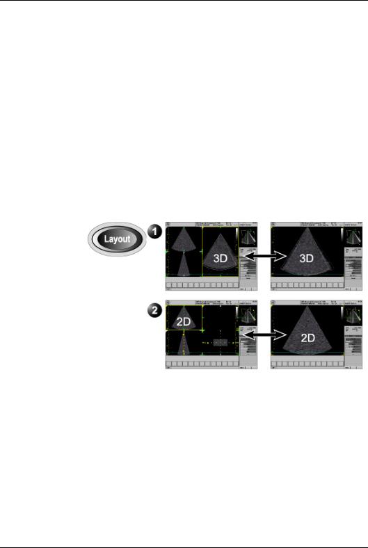
Display controls
Layout key on the front panel
Toggles the display between multi-screen and single-screen.
•Multi-screen:
•In Volume rendering: displays a volume rendering and 2D images from two perpendicular cut-planes.
•In Slice mode: displays 2D images from three cut-planes with the selected cut-plane in the main window.
•Single-screen:
•In Volume rendering: displays the volume rendering.
•In Slice mode: display the 2D image of the selected cut-plane.
1.Display options for Volume rendering
2.Display options for Slice mode
Figure 1-11: 4D mode display options
4D Gain (Active Gain rotary)
Affects the image “depth” or transparency. Too much 4D Gain applied will take away structures, too little will leave opaque “Gray clouds” in the ventricle.
4D/Multiplane Imaging User's Manual |
19 |
FD092081-01 |
|

4D Imaging
Zoom
Display zoom
Activated and adjusted by rotating the ZOOM rotary ( ). The rectangular shape of the zoomed area is displayed in the
Orientation window.
High Resolution (HR) zoom
HR zoom concentrates the image processing to a magnified, user selectable area in the image, resulting in a higher volume rate in the selected image area.
To be able to use the HR zoom in 4D imaging the HR zoom function must be activated in B mode before entering the 4D imaging mode.
20 |
4D/Multiplane Imaging User's Manual |
|
FD092081-01 |

4D Imaging
Using 4D mode - Vivid 7
1.Select the 3V probe and cardiac application.
2.Create an examination.
Parasternal view acquisition
1.In 2D mode, acquire a PLAX view and optimize the image quality, using DEPTH, GAIN, TGC...etc.
2.Press 4D.
3.Move the probe up or down so that the anterior wall is just inside the image in the lower left window in the 4D screen (Figure 1-12).
Note: In this position the volume is tilted to the left and the view position is looking towards the anterior wall.
Figure 1-12: PLAX volume rendering
4.Adjust 4D Gain to optimize the depth impression of the back wall.
5.To display a volume looking towards the inferior wall, press
FRONT/BACK.
The volume is tilted to the right and the view position is rotated 180 degrees.
4D/Multiplane Imaging User's Manual |
21 |
FD092081-01 |
|

4D Imaging
6.Press FREEZE, 2D FREEZE and rotate the volume to check the result.
7.Press IMG. STORE.
Apical view acquisition
1.In 2D mode, acquire a Apical view and optimize the image quality, using DEPTH, GAIN, TGC...etc.
2.Press 4D and follow the same procedure as for the PLAX view (see page 21).
Make sure to assess the image quality in the reference views and the volume rendering. Use FRONT/BACK to display the volume correctly.
3.Press FREEZE, 2D FREEZE and rotate the volume to check the result.
4.Press IMG. STORE.
22 |
4D/Multiplane Imaging User's Manual |
|
FD092081-01 |

4D Imaging
Full volume acquisition
Full volume acquisition is based on ECG triggering acquisition of sub-volumes. This technique enables the acquisition of a larger volume without compromising the resolution, by combining several sub-volumes acquired over two, three, four or six heart cycles (see Figure 1-7, page 13). When acquisition is done for the number of heart cycles set, the process is repeated replacing the oldest sub-volumes.
ECG triggering acquisition may by nature contain artifacts.
CAUTION
Artifacts may be caused by:
• Movements of the probe caused by the operator during acquisition.
• Movements of the patient during acquisition.
• Irregular heart rate during acquisition.
To validate the acquisition, perform a visual inspection in both the volume rendering and the elevation plane. Stitching artifacts are shown as visible transitions between the sub-volumes (Figure 1-13)
To avoid spatial artifacts, make sure that the probe and the patient are not moving during the acquisition. The patient should, if possible hold his/her breath. The ECG trace should be stable.
1.Connect the ECG device and make sure to obtain a stable ECG trace.
2.In 2D mode, acquire an Apical view and optimize the image quality, using DEPTH, GAIN, TGC...etc.
3.Press 4D.
4.Press FULL VOLUME.
The Full volume acquisition is started.
5.You may adjust ANGLE to get different view. The default top/down view is best for stitching quality assessment.
6.Ask the patient to hold her/his breath at end expiration. Keep the probe steady and look for stitching artifacts in both the volume rendering and the elevation plane in the lower left window of the screen (Figure 1-13).
Attention should be brought on stitching quality during acquisition rather than volume rendering quality.
4D/Multiplane Imaging User's Manual |
23 |
FD092081-01 |
|

4D Imaging
A: Acquisition with stitching artifacts |
B: Acquisition without stitching artifacts |
||
1. |
Elevation plane |
1. |
Elevation plane |
2. |
Volume rendering |
2. |
Volume rendering |
Figure 1-13: Stitching quality assessment
When no artifacts are seen over a few heart cycles, press
FREEZE.
24 |
4D/Multiplane Imaging User's Manual |
|
FD092081-01 |
Loading...