


GE TMW-800TC, TMW-1100E, TMW-1100M, TMW-800T, TMW-1100EC User Manual
...Turbo Air Inc.
1250 VICTORIA ST. CARSON, CA 90746, USA
PRINTED DATE: May. 2003
S/M No. :

S/M No. :
Service Manual
Microwave Oven
Model: TMW-1100E
TMW-1100EC
TMW-1100M
TMW-1100MC
TMW-800T
TMW-800TC
http://www.turboairinc.com |
May. 2003 |

PRECAUTIONS TO BE OBSERVED BEFORE AND DURING SERVICING TO AVOID POSSIBLE EXPOSURE TO EXCESSIVE MICROWAVE ENERGY
(a)Do not operate or allow the oven to be operated with the door open.
(b)Make the following safety checks on all ovens to be serviced before activating the magnetron or other microwave source, and make repairs if necessary: (1) Interlock operation, (2) Proper door closing, (3) Seal and sealing surfaces (arcing, wear, and other damage), (4) Damage to or loosening of hinges and latches (5) Evidence of dropping or abuse.
(c)Before turning on power to the microwave oven for any service test or inspection within the microwave generating compartments, check the magnetron, wave guide or transmission line, and cavity for proper alignment, integrity, and connections.
(d)Any defective or misadjusted components in the interlock, monitor, door seal and microwave generation and transmission systems shall be repaired, replaced, or adjusted by procedures described in this manual before the oven is released to the owner.
(e)A microwave leakage check to verify compliance with the Federal performance standard should be performed on each oven prior to release to the owner.
TABLE OF CONTENTS |
|
TMW-1100E / TMW-1100EC / TMW-1100M / TMW-1100MC |
|
SAFETY AND PRECAUTIONS.................................................................................................................................................. |
3 |
FOR SAFE OPERATION..................................................................................................................................................... |
3 |
FOR SAFE SERVICE PROCEDURES ............................................................................................................................... |
3 |
SPECIFICATIONS ...................................................................................................................................................................... |
4 |
EXTERNAL VIEW ....................................................................................................................................................................... |
5 |
OUTER DIMENSION........................................................................................................................................................... |
5 |
FEATURE DIAGRAM .......................................................................................................................................................... |
6 |
CONTROL PANEL............................................................................................................................................................... |
7 |
INSTALLATION .......................................................................................................................................................................... |
8 |
OPERATIONS AND FUNCTIONS ............................................................................................................................................. |
9 |
DISASSEMBLY AND ASSEMBLY .......................................................................................................................................... |
11 |
INTERLOCK MECHANISM AND ADJUSTMENT................................................................................................................... |
19 |
TROUBLE SHOOTING GUIDE ................................................................................................................................................ |
20 |
MEASUREMENT AND TEST................................................................................................................................................... |
27 |
MEASUREMENT OF THE MICROWAVE POWER OUTPUT ......................................................................................... |
27 |
MICROWAVE RADIATION TEST ..................................................................................................................................... |
28 |
COMPONENT TEST PROCEDURE................................................................................................................................. |
29 |
WIRING DIAGRAM................................................................................................................................................................... |
30 |
PRINTED CIRCUIT BOARD..................................................................................................................................................... |
34 |
CIRCUIT CHECK PROCEDURE ...................................................................................................................................... |
34 |
PCB CIRCUIT DIAGRAM.................................................................................................................................................. |
37 |
P.C.B. LOCATION NO....................................................................................................................................................... |
38 |
EXPLODED VIEW AND PARTS LIST ..................................................................................................................................... |
39 |
DOOR ASSEMBLY............................................................................................................................................................ |
39 |
CONTROL PANEL ASSEMBLY........................................................................................................................................ |
39 |
TOTAL ASSEMBLY........................................................................................................................................................... |
39 |
1

TMW-800T / TMW-800TC |
|
SPECIFICATIONS ............................................................................................................................................................. |
43 |
EXTERNAL VIEW.............................................................................................................................................................. |
44 |
1. OUTER DIMENSION....................................................................................................................................... |
44 |
2. FEATURE DIAGRAM ...................................................................................................................................... |
44 |
INSTALLATION ................................................................................................................................................................. |
45 |
OPERATIONS AND FUNCTIONS..................................................................................................................................... |
46 |
DISASSEMBLY AND ASSEMBLY.................................................................................................................................... |
47 |
INTERLOCK MECHANISM AND ADJUSTMENT............................................................................................................. |
54 |
TROUBLE SHOOTING GUIDE ......................................................................................................................................... |
55 |
MEASUREMENT AND TEST ............................................................................................................................................ |
57 |
1. MEASUREMENT OF THE MICROWAVE POWER OUTPUT ........................................................................ |
57 |
2. MICROWAVE RADIATION TEST ................................................................................................................... |
58 |
3. COMPONENT TEST PROCEDURE ............................................................................................................... |
59 |
WIRING DIAGRAM............................................................................................................................................................ |
60 |
EXPLODED VIEW AND PARTS LIST............................................................................................................................... |
62 |
1. DOOR ASSEMBLY ......................................................................................................................................... |
62 |
2. CONTROL PANEL ASSEMBLY...................................................................................................................... |
62 |
3. TOTAL ASSEMBLY......................................................................................................................................... |
62 |
2

SAFETY AND PRECAUTIONS
CAUTION : This Device is to be Serviced Only by Properly Qualified Service Personnel. Consult the Service Manual for Proper Service Procedures to Assure Continued Safety Operation and for Precautions to be Taken to Avoid Possible Exposure to Excessive Microwave Energy.
1.FOR SAFE OPERATION
Damage that allows the microwave energy (that cooks or heats the food) to escape will result in poor cooking and may cause serious bodily injury to the operator.
IF ANY OF THE FOLLOWING CONDITIONS EXIST, OPERATOR MUST NOT USE THE APPLIANCE. (Only a trained service personnel should make repairs.)
1)A broken door hinge.
2)A broken door viewing screen.
3)A broken front panel, oven cavity.
4)A loosened door lock.
5)A broken door lock.
The door gasket plate and oven cavity surface should be kept clean.
No grease, soil or spatter should be allowed to build up on these surfaces or inside the oven.
DO NOT ATTEMPT TO OPERATE THIS APPLIANCE WITH THE DOOR OPEN. The microwave oven has concealed switches to make sure the power is turned off when the door is opened. Do not attempt to by-pass.
DO NOT ATTEMPT TO SERVICE THIS APPLIANCE UNTIL YOU HAVE READ THIS SERVICE MANUAL.
2.FOR SAFE SERVICE PROCEDURES
1)If the oven is operative prior to servicing, a microwave emission check should be performed prior to servicing the oven.
2)If any certified oven unit is found to servicing, a microwave emission check should be performed prior to servicing the oven.
(a)inform the manufacturer, importer or assembler,
(b)repair the unit at no cost to the owner,
(c)attempt to ascertain the cause of the excessive leakage,
(d)tell the owner of the unit not to use the unit until the oven has been brought into compliance.
3)If the oven operates with the door open, the service person should tell the user not to operate the oven and contact the manufacturer and CDRH immediately.
CAUTION
MICROWAVE RADIATION
PERSONNEL SHOULD NOT BE EXPOSED TO THE MICROWAVE ENERGY WHICH MAY RADIATE FROM THE MAGNETRON OR OTHER MICROWAVE GENERATING DEVICE IF IT IS IMPROPERLY USED OR CONNECTED. ALL INPUT AND OUTPUT MICROWAVE CONNECTIONS. WAVEGUIDES FLANGES AND GASKETS MUST BE SECURED. NEVER OPERATE THE DEVICE WITHOUT A MICROWAVE ENERGY ABSORBING LOAD ATTACHED. NEVER LOOK INTO AN OPEN WAVEGUIDE OR ANTENNA WHILE THE DEVICE IS ENERGIZED.
3

SPECIFICATIONS
MODEL |
TMW-1100E / TMW-1100EC |
||
|
|
|
|
POWER SUPPLY |
120V~60HZ, SINGLE PHASE WITH GROUND |
||
|
|
|
|
POWER |
|
MICROWAVE |
1500 W / 1600 W |
|
|
|
|
GRILL |
|
||
CONSUMPTION |
|
|
|
|
|
||
|
|
||
|
|
COMBINATION |
|
MICROWAVE ENERGY OUTPUT |
1100 W |
||
|
|
|
|
MICROWAVE FREQUENCY |
2450MHz |
||
|
|
|
|
OUTSIDE DIMENSIONS (W X H X D) |
560X344X483mm (22.0X13.5X19 in.) |
||
|
|
|
|
CAVITY DIMENSIONS (W X H X D) |
369X221X400mm (14.5X8.7X15.7 in.) |
||
|
|
|
|
NET WEIGHT |
APPROX. 16.5kg (36.4lbs) |
||
|
|
|
|
TIMER |
59min. 99sec. |
||
|
|
|
|
FUNCTION SELECTIONS |
MICROWAVE |
||
|
|
|
|
POWER SELECTIONS |
4 LEVELS |
||
|
|
|
|
CAVITY VOLUME |
1.2 Cu. Ft |
||
|
|
|
|
* Specifications are subject to change without notice.
MODEL |
TMW-1100M / TMW-1100MC |
||
|
|
|
|
POWER SUPPLY |
120V~60HZ, SINGLE PHASE WITH GROUND |
||
|
|
|
|
POWER |
|
MICROWAVE |
1500 W / 1600 W |
|
|
|
|
GRILL |
|
||
CONSUMPTION |
|
|
|
|
|
||
|
|
||
|
|
COMBINATION |
|
MICROWAVE ENERGY OUTPUT |
1100 W |
||
|
|
|
|
MICROWAVE FREQUENCY |
2450MHz |
||
|
|
|
|
OUTSIDE DIMENSIONS (W X H X D) |
560X344X483mm (22.0X13.5X19 in.) |
||
|
|
|
|
CAVITY DIMENSIONS (W X H X D) |
369X221X400mm (14.5X8.7X15.7 in.) |
||
|
|
|
|
NET WEIGHT |
APPROX. 16.5kg (36.4lbs) |
||
|
|
|
|
TIMER |
10min. Single Speed |
||
|
|
|
|
FUNCTION SELECTIONS |
MICROWAVE |
||
|
|
|
|
POWER SELECTIONS |
5 LEVELS |
||
|
|
|
|
CAVITY VOLUME |
1.2 Cu. Ft |
||
|
|
|
|
* Specifications are subject to change without notice.
4
EXTERNAL VIEW (ELECTRICAL)
1. OUTER DIMENSION
560 |
483 |
|
344 |
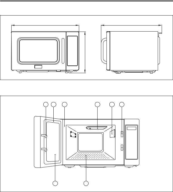
2. FEATURE DIAGRAM
3 |
5 |
4 |
7 |
8 |
1 |
2 6
1Safety interlock system
2Door viewing screen - Allows viewing of food. The screen is designed so that light can pass through, but not the radiation.
3Door hook - If the door is opened while the oven is operating, it will automatically shoot off.
4Oven cavity
5Door seal - Door seal maintains the microwave energy within the oven cavity.
6Glass tray - Made of special heat resistant glass. Food in a proper receptacle is placed on this tray for cooking.
7Stirrer cover - This is located on the ceiling with the stirrer fan.
8Inlet cover - Protect the air inlet from splattering of foods being cooked.
5
3. CONTROL PANEL
|
|
|
|
|
|
|
1 |
|
2 |
PROGRAM |
|
DEFROST |
3 |
||||
|
|
|
|
11 |
1 |
|
||
|
|
|
|
|
|
|
||
|
|
|
|
|
12 |
2 |
|
|
|
|
|
|
|
13 |
3 |
|
|
|
|
|
|
|
14 |
4 |
|
|
|
|
|
|
|
15 |
5 |
4 |
|
|
|
|
|
|
16 |
6 |
||
|
|
|
|
|
17 |
7 |
|
|
|
|
|
|
|
18 |
8 |
|
|
|
|
|
|
|
19 |
9 |
|
|
5 |
|
|
|
|
20 |
10 |
|
|
|
CHECK |
DOUBLE |
|
POWER |
7 |
|||
6 |
QUANTITY |
|||||||
|
|
|
||||||
|
|
|
|
|||||
|
STOP/CLEAR |
START/+30SEC |
|
|||||
9 |
|
|
|
|
|
|
8 |
|
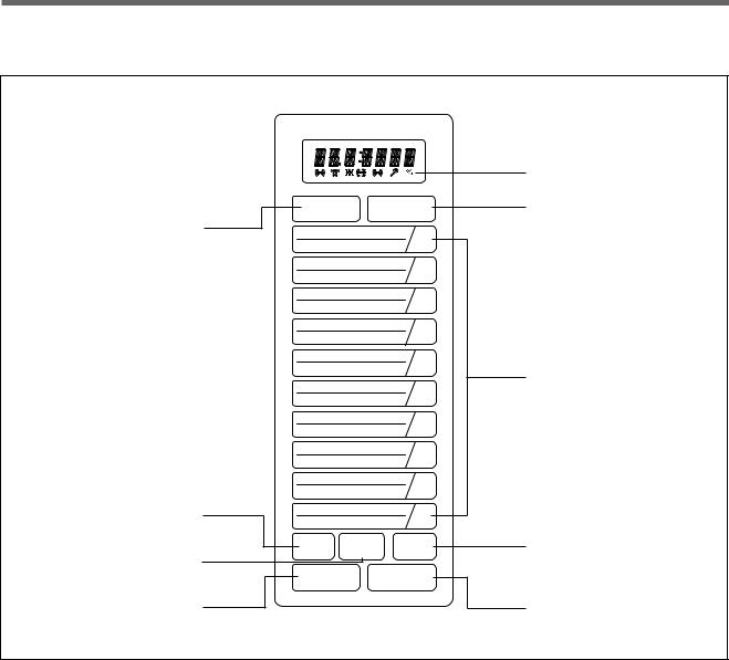
1Display - Cooking time, power level, indicators are displayed.
2Program - Used to save cooking data.
3Defrost - Used to defrost foods.
4Time Set Pad - Used to set the cooking time or cook preprogrammed foods.
5Check - Used to check cooking data.
6Double Quantity - Used to extend programmed cooking time.
7Power - Used to set power level.
8Stop/Clear - Used to stop the oven operation or to delete the cooking data.
9Start/+30sec - Used to start the oven and also used to set a reheat time.
6
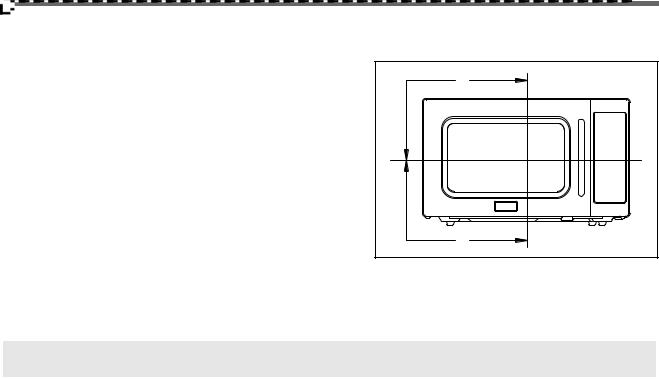
EXTERNAL VIEW (MECHANICAL)
1-1. OUTER DIMENSION |
|
560 |
483 |
|
344 |
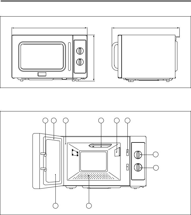
2-1. FEATURE DIAGRAM |
|
3 |
5 |
4 |
7 |
10 |
1 |
8
9
2 |
6 |
1.Safety interlock system
2.Door viewing screen - Allows viewing of food. The screen is designed so that light can pass through, but not the radiation.
3.Door hook - If the door is opened while the oven is operating, it will automatically shoout off.
4.Oven cavity
5.Door seal - Door seal maintains the microwave energy within the oven cavity .
6.Glass cooking tray - Made of special heat resistant glass. Food in a proper receptacle is placed on this tray for cooking.
7.Cover Stirrer - Protects the microwave outlet from splattering of foods being cooked.
8.Knob V.P.C - Used to select a microwave power level.
9.Knob timer - Used in setting cooking time for all function.
10.Inlet cover - Protects the air inlet from splattering of foods being cooked.
7

INSTALLATION
1. Steady, flat location.
This microwave oven should be set on a steady, flat surface.
2. Leave space behind and side.
All air vents should be kept clear. If all vents are covered during operation, the oven may be overheated and, eventually, cause oven failure.
3. Away from radio, and TV sets
Poor television reception and radio interference may result if the oven is located close to a TV, radio, antenna, or feeder and so on. Position the oven as far from them as possible.
4. Away from heating appliances and water taps
Keep the oven away from hot air, steam or splash when choosing a place to position it, or the insulation might be adversely affected and breakdowns occur.
5.Power supply
•Check your local power source.
This microwave oven requires a current of approximately 14.5 amperes, 120Volts, 60Hz grounded outlet.
1.A short power-supply cord is provided to reduce the risks resulting from becoming entangled in or trippping over a longer cord.
2.Longer cord sets or extension cords are available and may be used if care is exercised in their use.
3.If a long cord or extension cord is used:
1)The marked electrical rating of the cord set or extension cord should be at least as great as the electrical rating of the appliance.
2)The extension cord must be a grounding type 3-wire cord.
3)The longer cord should be arranged so that it will not drape over the counter top or tabletop where it can be pulled on by children or tripped over unintentionally.
6. Examine the oven after unpacking for any damage such as:
A misaligned door, broken door or a dent in cavity.
If any of the above are visible, DO NOT INSTALL, and notify dealer immediately.
8
OPERATIONS AND FUNCTIONS (ELECTRICAL)
1.Connect the main lead to an electrical outlet.
2.After placing the food in a suitable container, open the oven door and put it on the glass tray. The glass tray must always be in place during cooking.
3.Close the door securely.
4.The oven door can be opened at any time during operation by touching the door release button on the control panel.
The oven will automatically shut off. To restart the oven, close the door and then touch START.
5.Each time the pad is touched, a BEEP will sound to acknowledge the touch.
6.The oven automatically cooks on full power unless set to a lower power level.
7.The display will show : 0 when the oven is plugged in.
8.When the STOP/CLEAR pad is touched during the oven operation, the oven stops cooking and all information retained.
To erase all information touch, the STOP/CLEAR pad once more. If the oven door is opened during the oven operation, all information is retained.
9.If the START pad is touched and the oven does not operate, check the area between the door and door is closed securely. The oven will not start cooking until the door is completely closed or the program has been reset.
Make sure the oven is properly installed and plugged into the electrical outlet.
Wattage output chart
The power level is set by touching the POWER pad. The chart shows the display, the power level and the percentage of power.
Touch POWER pad. |
Power level(Display) |
Approximate Percentage of Power |
|
|
|
Once |
100 |
100% |
|
|
|
Twice |
80 |
80% |
|
|
|
3 times |
60 |
60% |
|
|
|
4 times |
40 |
40% |
|
|
|
9
OPERATIONS AND FUNCTIONS (MECHANICAL)
1.Connect the main lead to an electrical outlet.
2.After placing the food in a suitable container, open the oven door and put it on the glass tray. The glass tray must always be in place during cooking.
3.Close the door securely.
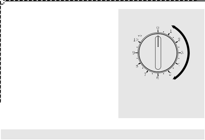
4.Choose cooking power level by setting V.P.C knob to the desired position. Refer to cookbook for recommended power levels.
5.Determine cooking time. Consult cookbook for recipe timing. Oven light turns on and cooling fan starts to operate. Microwave cooking starts.
6.You may open the door while the oven is operating. As soon as the door is opened, the safety mechanisms stop the generation of microwave power and the operation of cooking timer.
If you wish to change the time during cooking, simply adjust the timer to the desired time.
7.When the timer reaches zero, a bell will ring and the unit will turn off. Oven light turns off. If additional cooking time is needed and the door is closed, the oven will automatically start when the timer is reset.
•Various clicking noises may be heard when turning V.P.C knob. This is normal and does not affect the operation of your microwave oven.
Make sure the oven is properly installed and plugged into the electrical outlet.
Variable power cooking
ON and OFF cycle time of mechanical V.P.C switch is 30 seconds.
When the V.P.C knob is set to the desired position and timer knob to the desired position, the V.P.C switch has a cycle (ON/OFF time(sec.)) listed below.
Variable power setting |
Approximate Percentage |
|
|
Power level |
of Power |
|
|
HIGH |
100% |
|
|
MED HIGH |
77% |
|
|
MEDIUM |
55% |
|
|
LOW STAGE |
33% |
|
|
DEFROST |
17% |
|
|
10
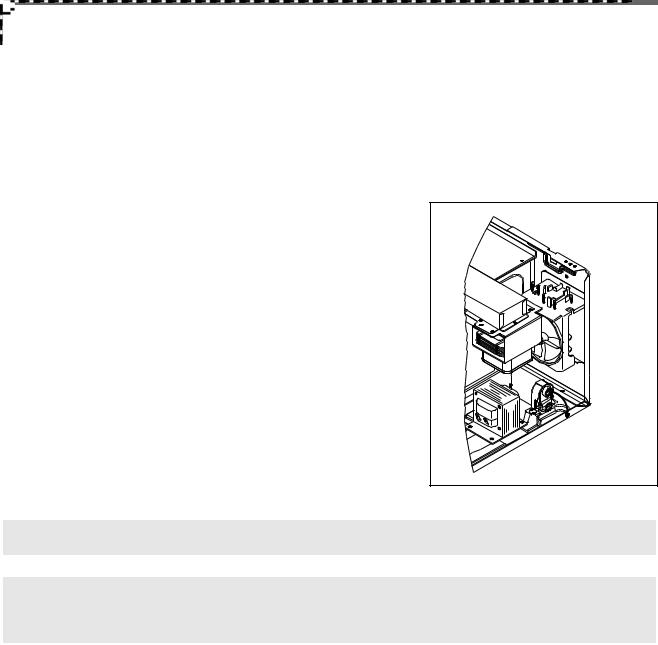
DISASSEMBLY AND ASSEMBLY
Cautions to be observed when trouble shooting.
Unlike many other appliances, the microwave oven is high-voltage, high-current equipment. It is completely safety during normal operation.
However, carelessness in servicing the oven can result in an electric shock or possible danger from a short circuit. You are asked to observe the following precautions carefully.
1.Always remove the power plug from the outlet before servicing.
2.Use an insulated screwdriver and wear rubber gloves when servicing the high voltage side.
3.Discharge the high voltage capacitor before touching any oven components or wiring.
(1)Check the grounding.
Do not operate on a 2-wire extension cord.
The microwave oven is designed to be used with grounded.
It is imperative, therefore, to make sure it is grounded properly before beginning repair work.
(2)Warning about the electric charge in the high voltage capacitor.
For about 30 seconds after the operation stopped and electric charge remains in the high voltage capacitor.
When replacing or checking parts, short between oven chassis and the negative high terminal of the high voltage capacitor, by using a properly insulated screwdriver to discharge.
4.When the 15A fuse is blown out due to the operation of the monitor switch; replace primary interlock switch, secondary interlock switch and
interlock monitor switch.
5. After repair or replacement of parts, make sure that the screws are SHORT properly tightened, and all electrical connections are tightened.
6. Do not operate without cabinet.
CAUTION : Service personnel should remove their watches whenever working close to or replacing the magnetron.
WARNING : When servicing the appliance, need a care of touching or replacing high potential parts because of electrical shock or exposing microwave. These parts are as follows - HV Transformer, Magnetron, HV Capacitor, HV Diode.
11
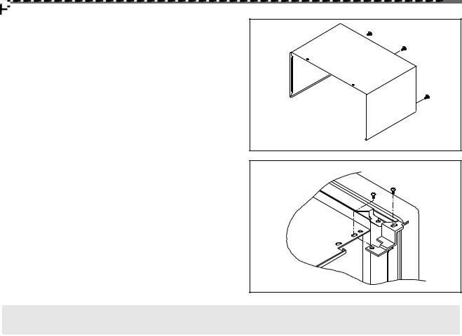
1.To remove cabinet
1)Remove three screws on cabinet back.
2)Push the cabinet backward.
2.To remove door assembly
1)Remove two screws which secure the stopper hinge top.
2)Remove the door assembly from top plate of cavity.
3)Reverse the above for reassembly.
NOTE : After replacing the door assembly, perform a check of correct alignment with the hinge and cavity front plate.
12

3. To remove door parts.
A04 |
A13 |
A05 |
A06 |
A07 |
A08
A09
A12 |
A10 |
A11
Door Assembly : 3511718600
A01 |
A02 |
A03 |
REF NO. |
PART CODE |
PART NAME |
DESCRIPTION |
Q’TY |
REMARK |
|
|
|
|
|
|
A01 |
3511610610 |
DOOR DECORATOR |
SUS T0.4 |
1 |
|
|
|
|
|
|
|
A02 |
7001401011 |
SCREW |
PAN 4*10 MFZN |
2 |
|
|
|
|
|
|
|
A03 |
3512206200 |
DOOR FRAME |
ABS |
1 |
|
|
|
|
|
|
|
A04 |
3517008100 |
BARRIER SCREEN*O |
GLASS T3.2 |
1 |
|
|
|
|
|
|
|
A05 |
3516602100 |
DOOR PLATE |
SBHG-1A T0.7 |
1 |
|
|
|
|
|
|
|
A06 |
3517007600 |
BARRIER SCREEN*I |
PE T0.1 |
1 |
|
|
|
|
|
|
|
A07 |
3512302310 |
DOOR GASKET |
LUPOL2300 |
1 |
|
|
|
|
|
|
|
A08 |
3516004100 |
SPECIAL SCREW |
T1 TRS LR4 POLE 4*10 MFZN |
2 |
|
|
|
|
|
|
|
A09 |
3513101200 |
HOOK |
POM |
1 |
|
|
|
|
|
|
|
A10 |
3515101800 |
SPRING HOOK |
PW1 |
1 |
|
|
|
|
|
|
|
A11 |
3512604800 |
DOOR HANDLE |
ABS CR COATING |
1 |
|
|
|
|
|
|
|
A12 |
3513586900 |
LABEL |
AL1020 T0.5 |
1 |
|
|
|
|
|
|
|
A13 |
3515204900 |
HINGE STOPPER*T AS |
KOC-1B0K0S |
1 |
|
|
|
|
|
|
|
(1)Remove the door gasket from door plate.
(2)Remove the barrier screen inner from door plate.
(3)Remove the door frame from door plate.
(4)Remove the hinge stopper top from door plate.
(5)Remove the spring and the hook.
(6)Remove the barrier screen outer from door frame.
(7)Reverse the above steps for reassembly.
13
4.Method to reduce the gap between the door seal and the oven front surface.
(1)To reduce gap located on part ‘A’.
• Loosen two screws on stopper hinge top, and then push |
A |
|
|
the door to contact the door seal to oven front surface. |
|
• Tighten two screws. |
|
(2) To reduce gap located on part ‘B’.
•Loosen two screws on stopper hinge under, and then push the door to contact the door seal to oven front
surface. |
|
• Tighten two screws. |
B |
NOTE : A small gap may be acceptable if the microwave leakage does not exceed 4mW/cm2.
14
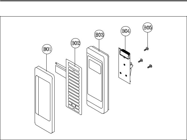
5. To remove control panel parts.
Control panel Assembly : PKCPSWAJ00
REF NO. |
PART CODE |
PART NAME |
DESCRIPTION |
Q’TY |
REMARK |
|
|
|
|
|
|
B01 |
3511610410 |
DECORATOR C-PANEL |
SUS T0.4 |
1 |
|
|
|
|
|
|
|
B02 |
351852400 |
TOUCH PAD |
KOR-1P5CBA |
|
|
|
|
|
|
|
|
B03 |
3516728510 |
CONTROL PANEL |
ABS AF-348, VT-0826 |
1 |
|
|
|
|
|
|
|
B04 |
PKMPMSAJ00 |
PCB AS |
KOR-1P5CBA |
1 |
|
|
|
|
|
|
|
B05 |
7122401211 |
TAP SCREW |
T2S TRS 4X12 MFZN |
4 |
|
|
|
|
|
|
|
(1)Remove the screw which secure the control panel, push up two snap fits and draw forward the control panel assembly.
(2)Remove four screws which secure the PCB assembly to control panel.
(3)Disconnect touch pad tail from the connector of the PCB assembly.
(4)Detach touch pad from the control panel.
(5)Pull out the decorator c-panel from the control panel.
(6)Reverse the above steps for reassembly.
15
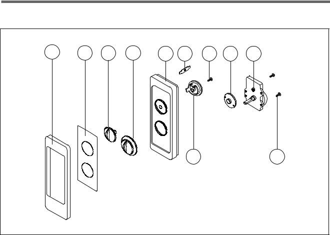
5-1. To remove control panel parts.
B01 |
B02 |
B03 |
B04 |
B05 |
B06 |
B08 |
B09 |
B10 |
B07 |
B11 |
Control panel Assembly : 3516728700
REF NO. |
PART CODE |
PART NAME |
DESCRIPTION |
Q’TY |
REMARK |
|
|
|
|
|
|
B01 |
3511610410 |
DECORATOR C-PANEL |
SUS T0.4 |
1 |
|
|
|
|
|
|
|
B02 |
3511611400 |
DECORATOR FILM |
PC T0.5 |
1 |
|
|
|
|
|
|
|
B03 |
3513407400 |
VPC KNOB |
ABS SG-0760D COATING |
1 |
|
|
|
|
|
|
|
B04 |
3513407500 |
TIMER KNOB |
ABS SG-0760D COATING |
1 |
|
|
|
|
|
|
|
B05 |
3516728500 |
CONTROL PANEL |
ABS VT-0825 |
1 |
|
|
|
|
|
|
|
B06 |
3515101600 |
SPRING FLAT |
SUS 301 T0.5 |
1 |
|
|
|
|
|
|
|
B07 |
3517400500 |
VPC KNOB COUPLER |
POM |
1 |
|
|
|
|
|
|
|
B08 |
7122401211 |
SCREW TAPPING |
T2S TRS 4*12 MFZN |
1 |
|
|
|
|
|
|
|
B09 |
3517400400 |
TIMER COUPLER |
POM |
1 |
|
|
|
|
|
|
|
B10 |
3518206300 |
TIMER |
NT10MKD01U-P |
1 |
|
|
|
|
|
|
|
B11 |
7122401211 |
TAP SCREW |
T2S TRS 4*12 MFZN |
2 |
|
|
|
|
|
|
|
1)Remove the screw which secure the control panel, push up two snap fits and draw forward the control panel assembly.
2)Remove two screws which secure the timer assembly.
3)Remove the timer assembly.
4)Pull out the timer knob from the timer.
5)Pull out the timer coupler from the timer.
6)Remove the screw which secure the V.P.C coupler.
7)Pull out the V.P.C coupler, V.P.C knob and flat spring from the control panel.
8)Reverse the above steps for reassembly.
16

6. To remove high voltage capacitor.
1)Remove a screw which secures the grounding ring terminal of the H.V. diode and the capacitor holder.
2) Remove the H.V. diode from the capacitor holder.
3) Reverse the above steps for reassembly.
High voltage circuit wiring
7.To remove magnetron.
1)Remove a screw which secures the magnetron.
2)Remove the magnetron.
3) Reverse the above steps for reassembly.
NOTE : Never install the magnetron without the metallic gasket plate which is packed with each magnetron to prevent microwave leakage. Whenever repair work is carried out on magnetron, check the microwave leakage. It shall not exceed 4mW/cm2 for a fully assembled oven with door normally closed.
Magnetron antenna
Metalic gasket
plate
Stub
Cooling fin
Filament terminal
<MAGNETRON>
17

8.To remove wind guide assembly.
1)Remove two screws which secures the wind guide assembly and cover hole *0 and noise filter.
2)Draw forward the wind guide assembly.
3)Pull the noise filter from the wind guide assembly.
4)Pull the fan from the motor shaft.
5)Remove two screws which secure the motor shaded pole.
6)Remove the motor shaded pole.
7)Reverse the above steps for reasembly.
Noise Filter:Only KOR-1P5CBB
|
KOR-1P55BB |
9. To remove H.V.transformer. |
|
1) |
Remove four screws holding the H.V.transformer. |
2) |
Remove the H.V.transformer. |
3) |
Reverse the above steps for reassembly. |
18
 Loading...