


GE Voluson E10
Ultrasound Training Manual

GE Voluson E10 Training Manual
Table of Contents |
|
Table of Contents................................................................................... |
i |
Module 1 Introduction.......................................................................... |
1 |
Other Course Offerings ........................................................................ |
1 |
Voluson E10................................................................................................... |
2 |
Module 2 System Hardware and Theory .............................................. |
3 |
Signal Flow .............................................................................................. |
3 |
System Block Diagram................................................................................... |
4 |
System Front End Components............................................................. |
5 |
Voluson E10 Front End Processor (FEP) ................................................. |
5 |
RTF - Probe Control Board ...................................................................... |
6 |
RSE - Pencil Probe Board (optional) ........................................................ |
6 |
RFM - (RF-Interface & Beamformer) FE Mainboard ............................... |
6 |
RFM Board - Interface FPGA.......................................................................... |
6 |
RFM Board - Processing FPGA....................................................................... |
6 |
RSX - (Beamformer Receiver/Transmitter) Extension Board.................. |
6 |
Front End Block Diagram............................................................................... |
7 |
System Backend Components............................................................... |
7 |
Back End Processor (BEP)........................................................................ |
7 |
Back End Block Diagram ................................................................................ |
8 |
PC-Motherboard ..................................................................................... |
8 |
Hard Disk Drive (HDD)............................................................................. |
9 |
Distribution of partitions at 500 Gbyte HDD................................................. |
9 |
Graphic Card......................................................................................... |
10 |
RTV - Video Management Board.......................................................... |
10 |
External I/O Connection Panel............................................................. |
10 |
Patient I/O Module .............................................................................. |
11 |
User Console ........................................................................................ |
11 |
Control Panel........................................................................................ |
12 |
Control Console Positioning ........................................................................ |
12 |
Video Monitor...................................................................................... |
13 |
Audio .................................................................................................... |
13 |
Power Distribution Components......................................................... |
14 |
Main Power Supply (RSP)..................................................................... |
14 |
Power Supply Block Diagram ...................................................................... |
15 |
RTB - Distribution Board Bottom ......................................................... |
16 |
Normal Power ON / Shut Down Sequence .......................................... |
16 |
Power On / Boot Up: ................................................................................... |
16 |
Normal Boot-up Process ............................................................................. |
17 |
Boot screen ................................................................................................. |
17 |
Normal Power Off / Shutdown.................................................................... |
18 |
Temperature Control ........................................................................... |
18 |
Module 3 Operating Modes................................................................ |
20 |
© 2017 Conquest Imaging |
|
|
i |

GE Voluson E10 Training Manual
B-Mode ............................................................................................. |
20 |
Harmonic Imaging.............................................................................. |
20 |
M-Mode ............................................................................................ |
21 |
Color Flow Doppler Mode .................................................................. |
21 |
Power Doppler................................................................................... |
22 |
Pulsed (PW) Doppler.......................................................................... |
22 |
Continuous Wave (CW) Doppler ......................................................... |
22 |
Other Modes ..................................................................................... |
23 |
Module 4 Network Configuration....................................................... |
24 |
DICOM............................................................................................... |
24 |
Prepare for Network Configuration .................................................... |
24 |
GE Dataflows ..................................................................................... |
24 |
TCP/IP Configuration.......................................................................... |
25 |
Device Setup...................................................................................... |
31 |
DICOM Configuration........................................................................... |
32 |
Controls ...................................................................................................... |
32 |
Adding a Service ......................................................................................... |
34 |
Services ................................................................................................ |
34 |
STORE / STORE3D Screen ........................................................................... |
36 |
MPPS .......................................................................................................... |
37 |
ST.COMMIT................................................................................................. |
37 |
STR.REPORT ................................................................................................ |
38 |
QUERY RETRIEVE ........................................................................................ |
38 |
WORKLIST ................................................................................................... |
38 |
REPORT ....................................................................................................... |
39 |
Module 5 Preventive Maintenance .................................................... |
40 |
System Backup................................................................................... |
40 |
Backup/Restore Database, Presets and Images................................... |
40 |
Backup - SYSTEM CONFIGURATION............................................................ |
40 |
Save Small Backup (Scan Settings) ....................................................... |
41 |
Load Backups........................................................................................ |
42 |
Load Small Backup (Scan Settings) ............................................................. |
42 |
Backup Full System Configuration (Full Backup).................................. |
44 |
External USB-Devices ......................................................................... |
46 |
Disconnection of External USB-Devices ............................................... |
47 |
Connect USB and Network Drives .............................................................. |
47 |
Cleaning the Air Filters ....................................................................... |
48 |
Cleaning the Trackball........................................................................ |
48 |
Motherboard Battery......................................................................... |
48 |
Module 6 General Safety Precautions ................................................ |
49 |
Electrical Safety.................................................................................... |
49 |
Electromagnetic Interference .............................................................. |
50 |
Electrostatic Discharge ESD Precautions.............................................. |
50 |
Fire Safety............................................................................................. |
51 |
General Cautions.................................................................................. |
51 |
ii |
© 2017 Conquest Imaging |

GE Voluson E10 Training Manual
Module 7 Troubleshooting ................................................................. |
52 |
Normal Power On/Boot Sequence...................................................... |
52 |
Connect AC (mains) Power to the Vivid E9/Logiq E9 ........................... |
52 |
Turn System ON ................................................................................... |
53 |
Sleep Mode .......................................................................................... |
53 |
Troubleshooting Log/Image Capture................................................... |
54 |
Shortcuts List........................................................................................ |
55 |
System Does Not Boot-up .................................................................. |
56 |
Monitor Troubleshooting ................................................................... |
57 |
Load Default Monitor Settings............................................................. |
57 |
Monitor Test ........................................................................................ |
58 |
Trouble Shooting Operator Panel Issues ............................................. |
59 |
No Audio .............................................................................................. |
59 |
No Video on LCD Display...................................................................... |
59 |
Wrong Key Activated on the Touch Panel ........................................... |
59 |
Touch Panel Not Responding ............................................................... |
60 |
Probe Recognition................................................................................ |
60 |
Module 8 Parts Replacement ............................................................. |
61 |
System Layout ................................................................................... |
61 |
System Power Down .......................................................................... |
62 |
Panel Removal................................................................................... |
62 |
Foot Rest .............................................................................................. |
62 |
Front Panel........................................................................................... |
63 |
Front Panel Screw Locations ....................................................................... |
63 |
Side Panel............................................................................................. |
64 |
Back Panel ............................................................................................ |
64 |
Boards and Modules .......................................................................... |
64 |
Power Supply ....................................................................................... |
65 |
Front End.............................................................................................. |
65 |
Back End............................................................................................... |
65 |
Monitor and Arm Replacement ........................................................... |
65 |
Module 9 System Adjustments........................................................... |
66 |
Control Console Positioning ............................................................... |
66 |
Control Console Rotation..................................................................... |
66 |
Control Console Height Adjustment .................................................... |
66 |
Video Monitor...................................................................................... |
66 |
Glossary............................................................................................... |
67 |
Acronyms ............................................................................................ |
70 |
Appendix 1 Network Configuration Worksheets................................ |
73 |
Checklist for Configuring Ultrasound System Network Parameters.... |
73 |
Print Device Information...................................................................... |
74 |
HIS/RIS Server Information .................................................................. |
75 |
DICOM Devices to Connect to System: ................................................ |
76 |
© 2017 Conquest Imaging |
iii |
|

GE Voluson E10 Training Manual
Other Needed Information: ................................................................. |
76 |
iv |
© 2017 Conquest Imaging |
GE Voluson E10 Training Manual
Module 1 Introduction
This manual is specific to the GE Voluson E10 systems field service training presented by the Conquest Imaging training department. After completing the training, you will:
Understand overall system operation.
Identify the parts, boards and modules.
Understand the role of each component in the system.
Be able to perform standard maintenance procedures.
Have the knowledge to troubleshoot common problems.
Be able to safely access and replace boards and modules.
Understand of some of the differences in configuration for different system versions.
Other Course Offerings
This course is one of many ultrasound training courses offered by Conquest Imaging.
The following are some of our current course offerings:
Basic Ultrasound
DICOM Standards and Networks
© 2017 Conquest Imaging |
1 |
|
GE Voluson E10 Training Manual
Preventive Maintenance
Probe Care and Handling
NFPA 99 Electrical Safety
Crash Course
OEM Platforms
You can use this margin for taking notes.
To see the full descriptions and the scheduling of these courses, please visit our training department website:
http://conquestimaging.com/education/
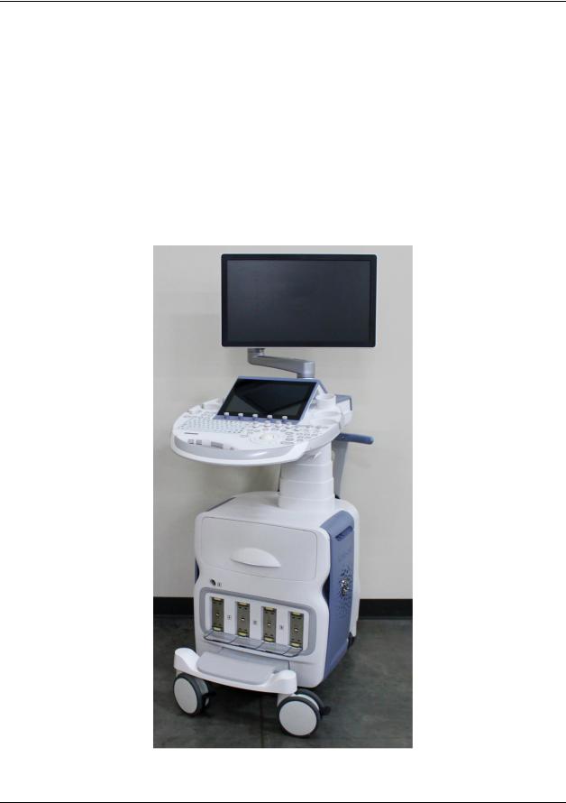
Voluson E10
The Voluson E10 is most often used for womens health-OB/GYN applications.
2 |
© 2017 Conquest Imaging |

GE Voluson E10 Training Manual
Module 2 System Hardware and Theory
The goal of the System Hardware and Theory Module is to provide you with a solid grounding on the purpose of the GE Voluson E10 system’s different components and how they function together within the system.
The three major functional blocks in all ultrasound systems are:
Front End – Includes transducer analog signal processing functions.
Back End – Includes user interface and system communication with DICOM systems.
Power Systems – Generates, regulates and supplies the required voltages to the various parts of the system.
Signal Flow
System configurations (GE dataflows) are stored on a hard drive inside the BEP, and all the necessary software is loaded from the hard drive on power up of the system.
The transmit bursts are routed from the RF interface to the relays where the ultrasound probes are connected. The signals are transmitted by the probes as ultrasound into the body. The input signals travel from the probe connector panel to the Front End Processor (FEP), then to the Back End Processor (BEP) for digital signal processing(DSP) and finally, the results are displayed on the monitor.
© 2017 Conquest Imaging |
3 |
|

GE Voluson E10 Training Manual
System Block
Diagram
4 |
© 2017 Conquest Imaging |

GE Voluson E10 Training Manual
System Front End Components
This section covers system frontend topics for the GE Voluson E10. Front End is a general term for the parts of the ultrasound system that receive the reflections from acoustic energy that have been transmitted into the body and perform the various signal processing functions on them needed to produce an ultrasound image. The following are some of the components and functions that are found in a typical ultrasound system front end:
Transducers – Transmit focused acoustic energy and receive the resultant reflections.
High voltage switches – Used for multiplexing (connects a particular transducer element to a particular transmitter/receiver pair)
High voltage transmitters – Transmit analog data from the transducers.
Time Gain Control Amp (TGC) – A variable gain amplifier (VGA) is used to compensate for image variations due to tissue depth.
Analog to Digital converter and noise filtering.
Digital Beamformers – Upconverts signals which increases sample rates. The signals are stored in memory, apodized and summed.
Beamformed Digital Signal Processing – The digital beamformed signals received are processed into visual and audio outputs the process of which depends on if the transducer is B-mode (2D), Doppler, PWD or CWD.
The front end manages the input from the transducers, performs Analog to Digital conversion, Digital to Analog conversion along with many other signal processing functions.
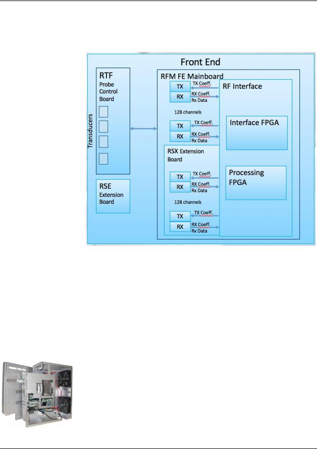
Voluson E10 Front End Processor (FEP)
In the Voluson E10 systems the front end beamforming electronics are comprised of the following boards:
© 2017 Conquest Imaging |
5 |
|
GE Voluson E10 Training Manual
To extend to 192 or 256 channels, the RSX- (Beamformer Receiver/Transmitter) Extension board is required.
RTF - Probe Control Board
The probe control board (RTF) recognizes different probe types and switches between the Probe Connectors (3 DLP-Connectors, 1 CWConnector) as required. The board contains:
One optional CW-Probe Connector
Three 408 pin Probe-Connectors
One 408pin Dummy-Probe Connector
Probe Select Relays
Probe Recognition
RSE - Pencil Probe Board (optional)
CW scanning is optional on the Voluson E10. This adapter board is for the connection of CW pencil probes is required for CW-Option.
RFM - (RF-Interface & Beamformer) FE Mainboard
The FrontEnd Mainboard supports Tx/Rx for 128 channels only.
RFM Board - Interface FPGA
The interface FPGA on the RFM board provides the following functions:
DMA logic
Beamformer Interface
RTF Control Interface
RTF FPGA Control Interface
RFM Board - Processing FPGA
The processing FPGA on the RFM board provides the following functions:
Ultrasound Data Pre-Processing
System Control
Motor Control
RSX - (Beamformer Receiver/Transmitter) Extension Board
Subset (for RFM) that is required to extend to 192 or 256 channels. All
6 |
© 2017 Conquest Imaging |
GE Voluson E10 Training Manual
components of RSX board are also present on RFM - (RF-Interface & Beamformer) FE Mainboard.
Front End Block
Diagram
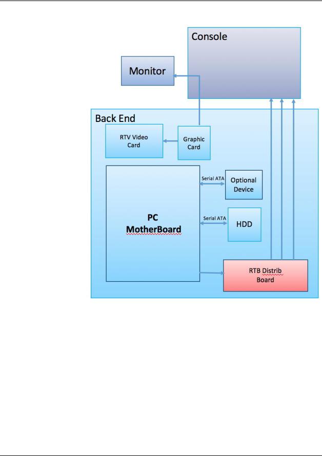
System Backend Components
This section describes the System Back End topics for the GE Voluson E10. The back end includes system blocks/components on the user interface side that perform functions such as master controller, signal processing, image memory, video layout, peripherals and user interface.
Back End Processor (BEP)
The Back End Processor (BEP) unit receives the data from the FEP electronics, stores it in memory, performs scan conversion to the pixel domain, and drives the system’s monitors.
Contains the HDD that holds the Base Image (Windows 7) and Application Software (System Specific). The BEP software also processes the Color Flow, Doppler, M-Mode data and the 3D/4D data.
© 2017 Conquest Imaging |
7 |
|
GE Voluson E10 Training Manual
Back End Block
Diagram
PC-Motherboard
The major tasks of the motherboard are system control and image processing/rendering for 2D/3D/4D. It also provides control for the DVD drive and User Interface (UI) via USB connections. There are four motherboard configurations for the Voluson E10:
ADVANTECH Micro-ATX + RTT/RTH6x
ADVANTECH Micro-ATX + RTH50
KONTRON Flex-ATX + RTT/RTH6x
KONTRON Flex-ATX + RTH50
Built in or external Components:
8 |
© 2017 Conquest Imaging |
GE Voluson E10 Training Manual
On Board VGA and Graphic Card
LAN
USB 2.0
USB 3.0
Sound
CPU: 3.1 GHz at 4 cores
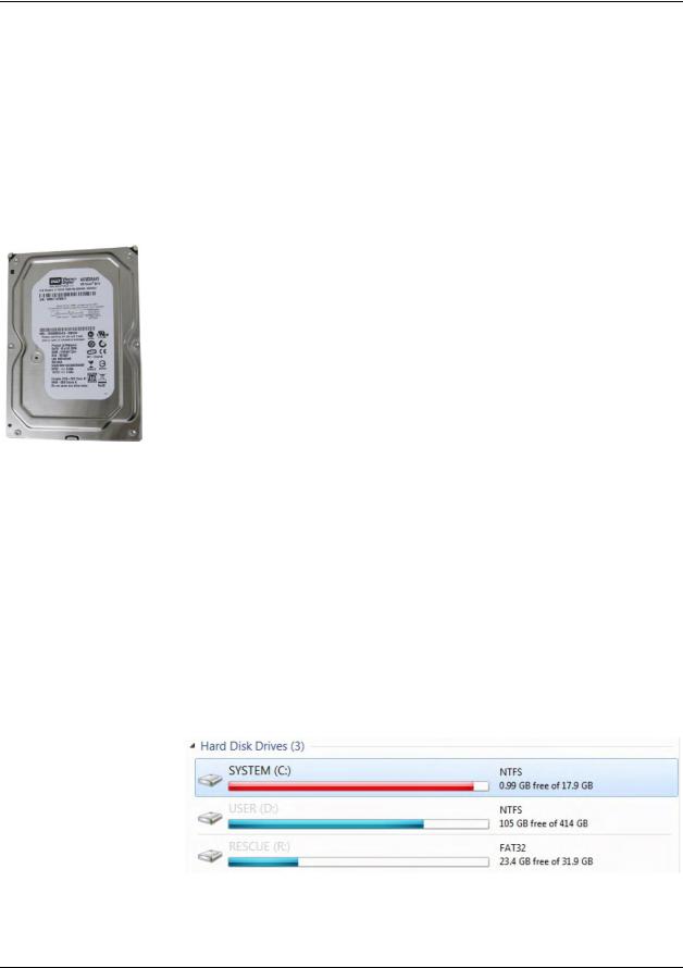
Hard Disk Drive (HDD)
The 500GB Hard Disk is the main storage device of the Voluson E- Series ultrasound system. The Voluson E-Series Hard disk drive (HDD) is divided into four different partitions:
C:System partition:
Operating System (Windows 7) including all Windows settings (IP-address, Network Name, etc.)
US-Application Software (UISAPP)
Global Service Platform Software
Software Options
D:User partition:
User Presets (Backup) database
Images (Archive), Patient-ID´s and Reports database
Service and System settings databases
R:Rescue partition:
Factory Images of the C: Partition for System recovery after HDD (Windows) crash.
Printer Drivers
LINUX partition: (not visible in Windows)
Linux operating system for rescue functionality.
Distribution of partitions at 500 Gbyte HDD
© 2017 Conquest Imaging |
9 |
|

GE Voluson E10 Training Manual
Graphic Card
The graphic Card supplies the RTV (Video manager) board with DVI Video. It offers dynamic contrast enhancement and color stretch video processing.
RTV - Video Management Board
Distributes DVI-D-information coming from the Graphic Card to the DVI-D (digital) and DVI-I (integrated) connectors. It also converts DVI- D-inputs to S-Video output(s). Displays external playback video and adds overlay graphics to it.
DVI-D output for the System Main Monitor
DVI-I output for external device (only RGB signals used)
S-Video output (2 channels)
S-Video input for external devices
USB connector for board configuration
External I/O Connection Panel
The GES30 external I/O connection Panel is found at the rear of the system and includes VGA, USB, Network and S-Video cables to the Voluson E-Series system.
HDMI OUT Connector for external monitor VGA OUT Connector for external monitor
USB 3.0 port USB 2.0 port
S-Video OUT S-Video OUT connector
Network DICOM input/output, twisted pair RJ-45 10/100 megabit/s
10 |
© 2017 Conquest Imaging |

GE Voluson E10 Training Manual
Inputs for the patient I/O are not meant for patient monitoring they are meant for correlation with patient scans only.
Patient I/O Module
The Patient I/O module allows ECG inputs to be used in conjunction with patient studies. The scanned image that is displayed is synchronized with the ECG and PCG traces. In Doppler or M-Mode, the traces are synchronized to that particular mode’s sweep. The AUX input is capable of handling external ECG signals from other diagnostic ECG devices.
User Console
The Voluson E-Series control console or User Interface(UI) consists of the following electronic sub-assemblies and/or functional components:
Display/Touch screen module:
WXGA display - 1280 x 800 pixels
Integrated USB to converter with USB2.0 High Speed Interface
Projected capacitive touch screen
Console module
Seven port USB 2.0 Hub controller:
Contols (Encoder/Joycoder) with integrated rotary/push/flip function
USB Trackball (2”) with dedicated buttons to emulate standard three button mouse
USB standard alphanumeric keyboard
USB extended keyboard with controller
LED Indicators with wide range dimming
LED to illuminate probe port connectors
DC/DC Converter:
Converts 12VDC input voltage to 5VDC and 3.3VDC output voltages for UI components.
© 2017 Conquest Imaging |
11 |
|
GE Voluson E10 Training Manual
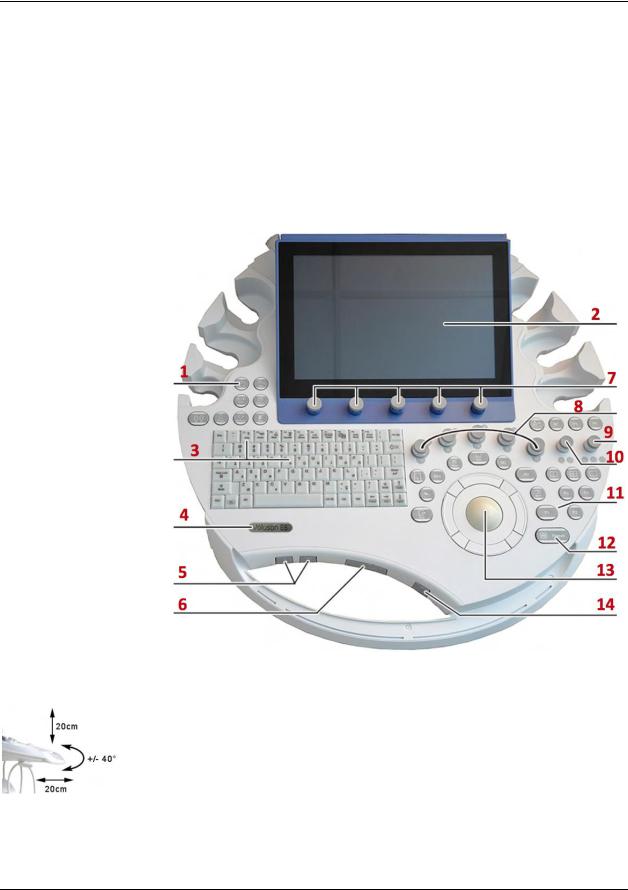
1.Power button ON/OFF/Standby
2.Touch Panel screen
3.Alphanumeric keyboard and F1 key (to invoke EUM)
4.Logo
5.Height adjustment control.
6.Console rotation button
7.Touch Panel rotary/push/flip controls
8.Five mode keys on/off (push), Gain (rotate) X,Y,Z rotary controls in 3D/4D Volume Mode
9.Focus Depth (flip), B- Image Angle (rotate), Focus Zones (push)
10.Zoom Box on/off (push), Zoom Size (rotate), B-Image Depth (flip)
11.P-keys
12.Freeze / Run key
13.Trackball and Trackball keys
14.Lamp on/off
Control Panel
The control panel is the main user interface, receives user inputs, communicates with the system host CPU via Universal Serial Bus (USB) ports and displays various outputs via the touch panel.
It includes the On/Off switch, controls used to manipulate picture quality, and controls used to measure and analyze, an alphanumeric keyboard and ergonomic controls.
Control Console Positioning
For ergonomic considerations the control console can be rotated, translated and adjusted in height. See Control Console Positioning in the Adjustments module of this manual.
Height adjustment: 20 cm (7.9 inch)
Translation adjustment: 20 cm (7.9 inch)
Rotation adjustment: +/- 40°
12 |
© 2017 Conquest Imaging |
GE Voluson E10 Training Manual
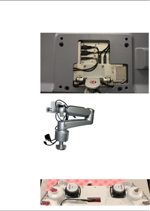
The monitor and it’s housing are sold as separate FRUs.
Video Monitor
The Voluson E-Series system video monitor displays the ultrasound images on a 23” color LCD.
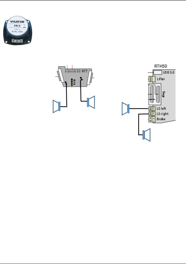
Audio
Audio is provided by two 8 Ohm speakers located in the user console on either side of the touch panel.
© 2017 Conquest Imaging |
13 |
|
GE Voluson E10 Training Manual
The audio system is used for:
Audio Doppler operation
Audio playback of recorded scan sessions
Audio error notification.
The audio signal is passed to the speakers from either the RTH50 board or the RTT board depending on the version of the system.
Power Distribution Components
The power distribution components in Voluson E10 systems are described in this section.
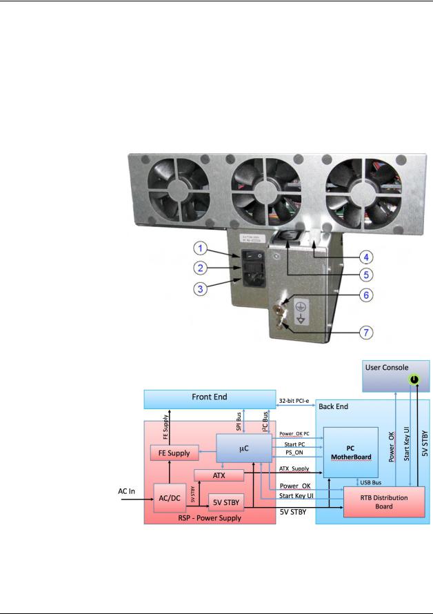
Main Power Supply (RSP)
The AC Power's main tasks are to supply the various internal subsystems with AC power and to galvanically isolate the system from the on site Mains Power System. To reduce inrush current, an inrush current limiter is implemented. From the input voltage from the Power Supply (RSP) the AC/DC converter generates all system supply voltages, which include the:
Front End voltages
Standby voltages
ATX motherboard supply
Tx voltages
14 |
© 2017 Conquest Imaging |
GE Voluson E10 Training Manual
In addition, the AC/DC device contains the digital motor amplifier.
Input Voltage Range: 100 - 240VAC; 50/60Hz
Auxiliary Output Voltage nominal 115VAC
All DC-supply voltages for built-in peripherals are also generated in the RSPPower Supply Module.
1 Circuit Breaker
2 Fuses (2x T10A H/250V)
3 connector for Main Power Cable
4 Lift system (12VDC)
5 Auxiliary Output
6 Protective Earth connection
7 Equipotential connection
Power Supply
Block Diagram
© 2017 Conquest Imaging |
15 |
|
GE Voluson E10 Training Manual
Note After turning off a system, wait at least 10 seconds before turning it on again. The system may not be able to boot if power is recycled too quickly.
1.Circuit Breaker
2.Fuses
3.Outlet Plug
RTB - Distribution Board Bottom
The following are the functions of the Distribution Board Bottom (RTB):
USB2.0 Interface, Board is connected to PC via a USB cable.
5 port USB2.0 Hub for connecting peripherals (e.g., optional ECG)
Feed through DC-Power and Signals for the console (12V_ATX, 5V_ATX, 5VSB, PWR_On, Start_Key, Loud speaker)
Multiplexer and Amplifier for PC-Sound, Doppler Audio and VCR/DVD-Recorder)
Normal Power ON / Shut Down Sequence
Power On / Boot Up:
1.Connect the main power cable to the back of the system.
2.If not already done, screw on the pull-out protection of the mains power cable with the two screws.
3.Connect the main power cable to a hospital grade power outlet with the proper rated voltage. Never use an adapter that would defeat the safety ground.
4.Switch ON the circuit breaker at the rear of the system.
When AC power is applied to the system, the ON/OFF standby button on the control console is amber, indicating that the system is in standby mode.
16 |
© 2017 Conquest Imaging |

GE Voluson E10 Training Manual
Note The mains outlet for the system peripheral auxiliary equipment are commonly switched with the ON/OFF standby button. The power switch of any attached printer(s) must be in ON position before starting the system. Some auxiliary equipment may switch itself to standby mode and must therefore be switched on separately.
Boot screen
5. Hold down the ON/OFF standby button (see: Figure 3-3 below) on the control console for ~3 seconds. The system automatically performs an initialization sequence which takes about two minutes and includes the following:
Loading the operating system.
Running a quick diagnostic check of the system.
Detecting connected probes.
When the ON/OFF standby button on the control console is pressed, the system starts and the operating system is loaded which then leads to activate the application software.
As soon as the software has been loaded, the system enters 2D-Mode with the probe and application that was used before the system shutdown.
Normal Boot-up Process
1.Power is distributed to peripherals, control console, monitor, FrontEnd and BackEnd processor.
2.The BackEnd processor and rest of the system starts with the sequence listed in following steps:
First the BIOS version is shown on the monitor.
Afterward the “Boot Screen” is displayed. (Voluson is highlighted).
© 2017 Conquest Imaging |
17 |
|
GE Voluson E10 Training Manual
Note After turning off a system, wait at least 10 seconds before turning it on again. The system may not be able to boot if power is recycled too quickly.
A full shutdown is also performed when pressing the ON/OFF standby button on the control console twice.
3.Back End processor is turned ON and starts to load the software.
4.The start screen is displayed on the monitor.
5.Start-up progress bars indicating software loading procedures, are displayed on the monitor.
6.The software initiates and sets up the FrontEnd electronics and the rest of the system (incl. clicking sound of relays on RTF board).
7.The keyboard backlight is lit.
8.As soon as the software has been loaded, the 2D screen is displayed on the monitor.
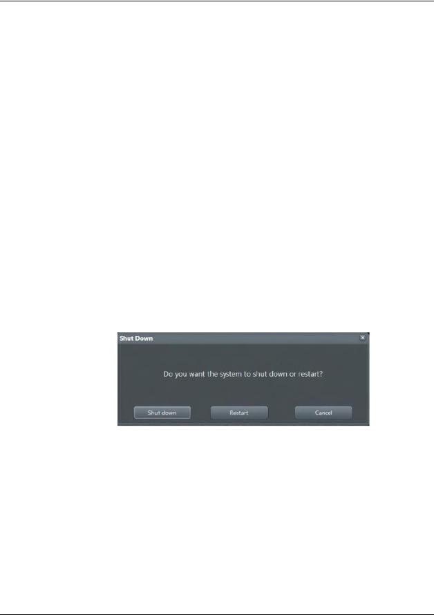
Normal Power Off / Shutdown
To shutdown the system:
1.If not already in read mode, freeze the image.
2.Press the ON/OFF Standby button on the control console. Following dialog appears:
3.Select Shutdown. The system performs an automatic full shutdown sequence.
4.Switch OFF the circuit breaker at the rear of the system.
Temperature Control
BTU Info
The main air inlet is through a single filter at the rear of the Voluson E-Series system:
18 |
© 2017 Conquest Imaging |

GE Voluson E10 Training Manual
Air holes in the RSP power supply allow the air to pass through; the three fans inside the RSP pull in the air and circulate it through the beamformer.
The two backend fans blow air through the GEB-box (along its internal components and the PCMotherboard). The warm air exits the system through holes in the left side panel (Main Air Outlet).
© 2017 Conquest Imaging |
19 |
|
GE Voluson E10 Training Manual
Module 3 Operating Modes
The following general operating modes are available on Voluson E10 systems:
B-Mode
B-Mode is a two-dimensional image of the amplitude of the echo signal. It is used for location and measurement of anatomical structures and for spatial orientation during operation of other modes. In B mode, a two-dimensional cross-section of a threedimensional soft tissue structure such as the heart is displayed in real time.
Ultrasound echoes of different intensities are mapped to different gray scale or color values in the display. The outline of the 2D (B- Mode) (B-Mode) cross-section is a sector, depending on the particular transducer used. B-mode can be used in combination with any other mode.
Harmonic Imaging
Tissue Harmonic Imaging, acoustic aberrations due to tissue, are minimized by receiving and processing the second harmonic signal that is generated within the insonified tissue. Coded Harmonics enhances near field resolution for improved small parts imaging as well as far field penetration. It diminishes low frequency amplitude noise and improves imaging technically difficult patients.
It may be especially beneficial when imaging isoechoic lesions in shallow-depth anatomy in the breast, liver and hard-to-visualize fetal anatomy. Coded Harmonics may improve the B-Mode (2D (B-Mode)) image quality without introducing a contrast agent.
20 |
© 2017 Conquest Imaging |
 Loading...