


VOLUSON® 730
INSTRUCTION MANUAL
GE Medical Systems
Kretztechnik GmbH & Co OHG

GE Medical Systems
Kretz Ultrasound
Instruction Manual
H46611E
Direction 105838
Revision 3
from Software Version Sys D03-1.07 onwards
VOLUSON® 730
0366
Copyright© 2002, 2003 by GE Medical Systems – Kretztechnik GmbH & Co. OHG

Revision History
|
|
|
|
Table i-1: Reason for Change |
|
|
|
|
|
|
|
|
|
|
|
REV |
DATE |
|
REASON FOR CHANGE |
||||
|
|
|
|
|
|
|
|
Rev.0 |
January 30, 2002 |
|
Software Version Sys D03-1.06 |
|
|
||
|
|
|
|
|
|
|
|
Rev.1 |
April 15, 2002 |
|
Software Version Sys D03-1.06F |
||||
|
|
|
|
|
|
|
|
Rev.2 |
October 11, 2002 |
|
Software Version Sys D03-1.06G |
||||
|
|
|
|
|
|
|
|
Rev.3 |
July 23, 2003 |
|
Software Version Sys D03-1.07 |
|
|
||
|
|
|
|
|
|
|
|
|
|
|
Table i-2: List of effective Pages |
|
|
||
|
|
|
|
|
|
||
|
|
CHAPTER- / PAGE NUMBER |
|
REV # |
|
||
|
|
|
|
|
|
|
|
|
|
Cover |
|
|
|
3 |
|
|
|
|
|
|
|
||
|
|
Revision History |
|
3 |
|
||
|
|
|
|
|
|
|
|
|
|
Contents |
|
|
|
3 |
|
|
|
|
|
|
|
||
|
|
Chapter 1 - General |
|
3 |
|
||
|
|
|
|
|
|
||
|
|
Chapter 2 - Safety |
|
3 |
|
||
|
|
|
|
|
|
||
|
|
Chapter 3 - Description of the System |
|
3 |
|
||
|
|
|
|
|
|
||
|
|
Chapter 4 - Starting the System |
|
3 |
|
||
|
|
|
|
|
|
||
|
|
Chapter 5 - Electronic User Manual (EUM) |
|
3 |
|
||
|
|
|
|
|
|
||
|
|
Chapter 6 - Connections |
|
3 |
|
||
|
|
|
|
|
|
||
|
|
Chapter 7 - Technical Data / Information |
|
3 |
|
||
|
|
|
|
|
|
|
|
Voluson® 730 - |
Instruction Manual |
105838 Rev. 3 |
i-1 |

This page intentionally left blank.
Voluson® 730 - |
Instruction Manual |
i-2 |
105838 Rev. 3 |

CONTENTS
REVISION HISTORY………………………………………………………………………i-1
1. GENERAL....................................................................................................... |
1-2 |
2. |
SAFETY .......................................................................................................... |
2-2 |
2.1 |
Important Instructions for Safety ...................................................................................... |
2-2 |
2.2 |
Electric installation.............................................................................................................. |
2-3 |
2.3 |
Symbols used ........................................................................................................................ |
2-3 |
2.4 |
Remarks for safe Use........................................................................................................... |
2-5 |
2.5 |
Environmental Conditions for Operation ......................................................................... |
2-6 |
2.6 |
Instruction for Use............................................................................................................... |
2-6 |
2.7 |
Biopsy Lines ......................................................................................................................... |
2-7 |
2.8 |
ECG-preamplifier (MAN)................................................................................................... |
2-7 |
2.9 |
Cleaning and Maintenance ................................................................................................. |
2-8 |
2.10 |
Safety Test ............................................................................................................................ |
2-8 |
2.11 |
Manufacturer Responsibility.............................................................................................. |
2-9 |
2.12 |
Service Documents............................................................................................................... |
2-9 |
2.13 |
Basic interaction between Ultrasound and Matter........................................................... |
2-9 |
2.13.1 |
Bioeffects......................................................................................................................... |
2-9 |
2.13.2 |
Intensities Measured in Water and recalculated In Situ ................................................ |
2-11 |
2.13.3 |
Derivation and Meaning of the thermal and mechanical Indices .................................. |
2-12 |
2.13.4 |
FDA-Limits for Acoustic Output and Bioeffects .......................................................... |
2-15 |
2.13.5 |
Summary........................................................................................................................ |
2-15 |
2.13.6 |
Display Accuracy of the Indices.................................................................................... |
2-16 |
2.13.7 |
Recommendation to use and for the Need for following the ALARA Principle........... |
2-16 |
2.13.8 |
Notes for Acoustic Output Tables for Track 3 .............................................................. |
2-17 |
2.13.9 |
Acoustic Measurement Uncertainties ............................................................................ |
2-18 |
2.13.10 Acoustic Output Tables ................................................................................................. |
2-18 |
|
2.14 |
3D-Resolution and Sensitivity........................................................................................... |
2-19 |
2.15 |
Measurement Accuracy of the System............................................................................. |
2-20 |
2.16 |
Disposal............................................................................................................................... |
2-20 |
Voluson® 730 - Instruction Manual
105838 Rev. 3 |
CONTENTS - 1 |

CONTENTS
3. |
DESCRIPTION OF THE SYSTEM.................................................................. |
3-2 |
|
3.1 |
Product Description ............................................................................................................. |
3-2 |
|
|
3.1.1 |
Biological Safety.............................................................................................................. |
3-3 |
|
3.1.2 |
Limitation Vectors ........................................................................................................... |
3-3 |
|
3.1.3 |
Bioeffects ......................................................................................................................... |
3-4 |
3.2 |
Mechanical Design ............................................................................................................... |
3-4 |
|
|
3.2.1 |
System Configuration ...................................................................................................... |
3-4 |
|
3.2.2 |
Mechanical Adjustment ................................................................................................... |
3-5 |
3.3 |
System Assembly.................................................................................................................. |
3-6 |
|
|
3.3.1 |
Basic System.................................................................................................................... |
3-6 |
|
3.3.2 |
Optional Modules............................................................................................................. |
3-6 |
|
3.3.3 |
Optional Peripheral .......................................................................................................... |
3-7 |
3.4 |
Concept of Operation .......................................................................................................... |
3-7 |
|
3.5 |
Layout of menus................................................................................................................... |
3-8 |
|
|
3.5.1 |
Layout of the 2D-Mode Main Menu................................................................................ |
3-9 |
|
3.5.2 |
Changing of Menus........................................................................................................ |
3-10 |
|
3.5.3 |
Position of Display Annotation...................................................................................... |
3-10 |
|
3.5.4 |
Control Panel ................................................................................................................. |
3-12 |
3.6 |
Hardkeys............................................................................................................................. |
3-13 |
|
|
3.6.1 |
Function of the Trackball at Diverse Dialog Pages ....................................................... |
3-17 |
4 STARTING THE SYSTEM................................................................................. |
4-2 |
|
4.1 |
General Remarks ................................................................................................................. |
4-2 |
4.2 |
Safety Warnings ................................................................................................................... |
4-2 |
4.3 |
Turn on Power...................................................................................................................... |
4-3 |
4.4 |
Transducer Connection ....................................................................................................... |
4-4 |
4.5 |
Probe/Program Selection..................................................................................................... |
4-5 |
4.5.1 |
Starting the System .......................................................................................................... |
4-6 |
4.5.2 |
To freeze an Image........................................................................................................... |
4-6 |
Voluson® 730 - Instruction Manual
2 - CONTENTS |
105838 Rev. 3 |

CONTENTS
5 ELECTRONIC USER MANUAL (EUM) ............................................................. |
5-2 |
|
5.1 |
To Exit the Electronic User Manual .................................................................................. |
5-2 |
5.2 |
Navigation Tools .................................................................................................................. |
5-3 |
5.3 |
Help Book - Navigation Tools............................................................................................. |
5-4 |
5.3.1 |
To View the Contents ...................................................................................................... |
5-4 |
5.3.2 |
To Use the Index.............................................................................................................. |
5-5 |
5.3.3 |
To Search for a Topic ...................................................................................................... |
5-6 |
5.3.4 |
To Save a Favorite Topic................................................................................................. |
5-7 |
6. |
CONNECTIONS.......................................................................................................... |
6-2 |
||
6.1 |
How to connect Auxiliary Devices safely ........................................................................... |
6-2 |
||
6.2 |
To Connect internal and external Accessories .................................................................. |
6-3 |
||
|
6.2.1 |
|
Main Module ................................................................................................................... |
6-4 |
|
6.2.2 |
|
Power Supply (rear Side)................................................................................................. |
6-6 |
|
6.2.3 |
|
Power Supply (for Auxiliary Equipments) ...................................................................... |
6-7 |
|
6.2.4 |
|
Side of the Main Module-Connectors.............................................................................. |
6-8 |
|
6.2.5 |
|
Connector Panel (rear Side)............................................................................................. |
6-9 |
|
6.2.6 |
|
Color Video Monitor Connection.................................................................................. |
6-10 |
|
6.2.7 |
|
B/W Video Printer Connection Scheme ........................................................................ |
6-11 |
|
6.2.8 |
|
S-VHS Videorecorder Connection Scheme................................................................... |
6-12 |
|
6.2.9 |
|
Color Video Printer Connection Scheme....................................................................... |
6-13 |
|
6.2.9.1 |
Sony UP-D2600S...................................................................................................... |
6-13 |
|
|
6.2.9.2 |
Sony UP-D21MD ..................................................................................................... |
6-14 |
|
|
6.2.9.3 |
Mitsubishi CP770DW............................................................................................... |
6-15 |
|
|
6.2.10 |
|
Line Printer Connection Scheme ................................................................................... |
6-16 |
|
6.2.11 |
|
ECG-preamplifier (MAN 6) Connection....................................................................... |
6-17 |
|
6.2.12 |
|
Foot Switch (MFT 7) Connection.................................................................................. |
6-18 |
6.3 |
Important Notes: Connecting Auxiliary Equipment...................................................... |
6-19 |
||
Voluson® 730 - Instruction Manual
105838 Rev. 3 |
CONTENTS - 3 |

CONTENTS
7. |
TECHNICAL DATA/INFORMATION.............................................................. |
7-2 |
7.1 |
Power Supply........................................................................................................................ |
7-3 |
7.2 |
Transmitter........................................................................................................................... |
7-4 |
7.3 |
Receiver................................................................................................................................. |
7-4 |
7.4 |
Scan Converter..................................................................................................................... |
7-5 |
7.5 |
Cine Loop Memory .............................................................................................................. |
7-5 |
7.6 |
Display Modes ...................................................................................................................... |
7-5 |
7.7 |
Signal Processing.................................................................................................................. |
7-6 |
7.8 |
Data Entry ............................................................................................................................ |
7-6 |
7.9 |
Measurement and Calculation Programs .......................................................................... |
7-6 |
7.10 |
User Program Memory........................................................................................................ |
7-7 |
7.11 |
Volume Scan Module........................................................................................................... |
7-8 |
7.12 |
Spectral Doppler .................................................................................................................. |
7-9 |
7.13 |
Color Doppler..................................................................................................................... |
7-10 |
7.14 |
Tissue Doppler.................................................................................................................... |
7-11 |
7.15 |
Power Doppler.................................................................................................................... |
7-11 |
7.16 |
Interfaces ............................................................................................................................ |
7-12 |
7.17 |
Monitor ............................................................................................................................... |
7-13 |
7.18 |
External Drives................................................................................................................... |
7-13 |
7.19 |
MAN ECG preamplifier................................................................................................... |
7-14 |
Voluson® 730 - Instruction Manual
4 - CONTENTS |
105838 Rev. 3 |

General
1. |
General.......................................................................................................................... |
1-2 |
Voluson® 730 - Instruction Manual
105838 Rev. 3 |
1-1 |

General
1. General
The Voluson® 730 is a professional Diagnostic Ultrasound System which transmits Ultrasound waves into the body tissues and forms Images from the information contained within the received echoes.
The Voluson® 730 is an Active Diagnostic Medical Product belonging to Class IIa according to the MDD 93/42/EWG regulation for use on human patients.
The Voluson® 730 is developed and produced by the company Kretztechnik.
For more Information please contact:
GE Medical Systems Kretztechnik GmbH & Co OHG
Tiefenbach 15 |
Telephone: |
+43-7682-3800-0 |
A-4871 Zipf |
Fax.: |
+43-7682-3800-47 |
Austria |
E-mail: |
kretz@med.ge.com |
|
Internet: |
http://www.gemedical.com |
Voluson® 730 - Instruction Manual
1-2 |
105838 Rev. 3 |
|
|
|
Safety |
|
|
|
|
2. |
Safety............................................................................................................................. |
2-2 |
|
2.1 |
Important Instructions for Safety ...................................................................................... |
2-2 |
|
2.2 |
Electric installation.............................................................................................................. |
2-3 |
|
2.3 |
Symbols used ........................................................................................................................ |
2-3 |
|
2.4 |
Remarks for safe Use........................................................................................................... |
2-5 |
|
2.5 |
Environmental Conditions for Operation ......................................................................... |
2-6 |
|
2.6 |
Instruction for Use............................................................................................................... |
2-6 |
|
2.7 |
Biopsy Lines ......................................................................................................................... |
2-7 |
|
2.8 |
ECG-preamplifier (MAN)................................................................................................... |
2-7 |
|
2.9 |
Cleaning and Maintenance ................................................................................................. |
2-8 |
|
2.10 |
Safety Test......................................................................................................................... |
2-8 |
|
2.11 |
Manufacturer Responsibility .......................................................................................... |
2-9 |
|
2.12 |
Service Documents ........................................................................................................... |
2-9 |
|
2.13 |
Basic interaction between Ultrasound and Matter ....................................................... |
2-9 |
|
2.13.1 |
Bioeffects........................................................................................................................ |
2-9 |
|
2.13.2 Intensities Measured in Water and recalculated In Situ ............................................... |
2-11 |
||
2.13.3 Derivation and Meaning of the thermal and mechanical Indices ................................. |
2-12 |
||
2.13.4 FDA-Limits for Acoustic Output and Bioeffects ......................................................... |
2-15 |
||
2.13.5 |
Summary ...................................................................................................................... |
2-15 |
|
2.13.6 Display Accuracy of the Indices................................................................................... |
2-16 |
||
2.13.7 Recommendation to use and for the Need for following the ALARA Principle.......... |
2-16 |
||
2.13.8 Notes for Acoustic Output Tables for Track 3 ............................................................. |
2-17 |
||
2.13.9 |
Acoustic Measurement Uncertainties........................................................................... |
2-18 |
|
2.13.10 |
Acoustic Output Tables ............................................................................................ |
2-18 |
|
2.14 |
3D-Resolution and Sensitivity ....................................................................................... |
2-19 |
|
2.15 |
Measurement Accuracy of the System ......................................................................... |
2-20 |
|
2.16 |
Disposal ........................................................................................................................... |
2-20 |
|
Voluson® 730 - Instruction Manual
105838 Rev. 3 |
2-1 |

Safety
2.Safety
The VOLUSON® 730 scanner system has been designed for utmost safety for patient and user. Read the following chapters thoroughly before you start working with the machine! The manufacturer guarantees safety and reliability of the system only when all the following cautions and warnings are observed.
INTENDED USE
Please note that the cautions and warnings described in this section have to be observed like Electrical Installations, Important Instructions for Safety, Environmental conditions for operation etc.
Please see section 2.1 to 2.16
Also take care that the diagnostic possibilities of modes and the clinical applications of probes (indications for use) are known, please review Description of the System (chapter 3) resp. General and technical description of the concerned Probe User’s manual.
For Technical Data see: chapter 7 and Connections internal and external accessories see: chapter 6. Respectively see chapter 22 and chapter 20 of the Basic User Manual for Voluson® 730.
FEDERAL LAW RESTRICTS THIS DEVICE TO SALE BY OR ON THE ORDER OF A PHYSICIAN
WARNING: describes precautions necessary to prevent risks of live.
CAUTION: describes precautions necessary to protect the equipment.
CAUTION: The manual refers to probes that can be connected to the device.
It might be possible that some probes are NOT available in some countries!!
CAUTION: Some features and options are not available in some countries!!
2.1Important Instructions for Safety
WARNING ! This equipment must not be used in the presence of inflammable gases (e.g. anesthetic gases) => explosion hazard!
WARNING ! The system must only be connected to a fully intact mains socket with a grounded guard wire via an appropriate mains cable. The ground wire must never be removed or disconnected.
WARNING ! No covers or panels must be removed from the system (high-voltage risk). GE Medical Systems-authorized personal must only perform Service and repairs. Attempting do-it-yourself repairs invalidate warranty and are an infringement to regulations and are inadmissible acc. to IEC 60601-1.
Under the condition of regular maintenance by the authorized service personal a lifetime of the equipment of 10 years may be expected.
WARNING ! Only accessories explicitly recognized by the system manufacturer GE Medical Systems Kretztechnik GmbH & Co.OHG may be used in connection with the system.
Voluson® 730 - Instruction Manual
2-2 |
105838 Rev. 3 |

Safety
WARNING ! The footswitch must not be used in operating rooms!
WARNING !
There have been reports of severe allergic reactions to medical devices containing latex (natural rubber). Operators are advised to identify latex-sensitive patients and be prepared to treat allergic reactions promptly.
Refer to FDA Medical Alert MDA91-1
2.2Electric installation
The system must be exclusively installed in medically used rooms. The equipment conforms with regulations for electrical safety (EN60.601-1/1990 resp. ÖVE-MG/EN60.601-1/1991 and IEC 60601) and safety class IIa according to the MDD 93/42/EWG regulation for use on humans patients. Probes are rated Type BF. Local safety regulations may require an additional connection between the potential equilibrium bolt and the building's grounding system.
CAUTION ! Before switching on the first time, the local mains voltage and frequency are to be checked against the values indicated on the VOLUSON® 730 nameplate on the rear panel. Authorized personnel must only perform any change to the system.
The minimum required house installation must have 16A.
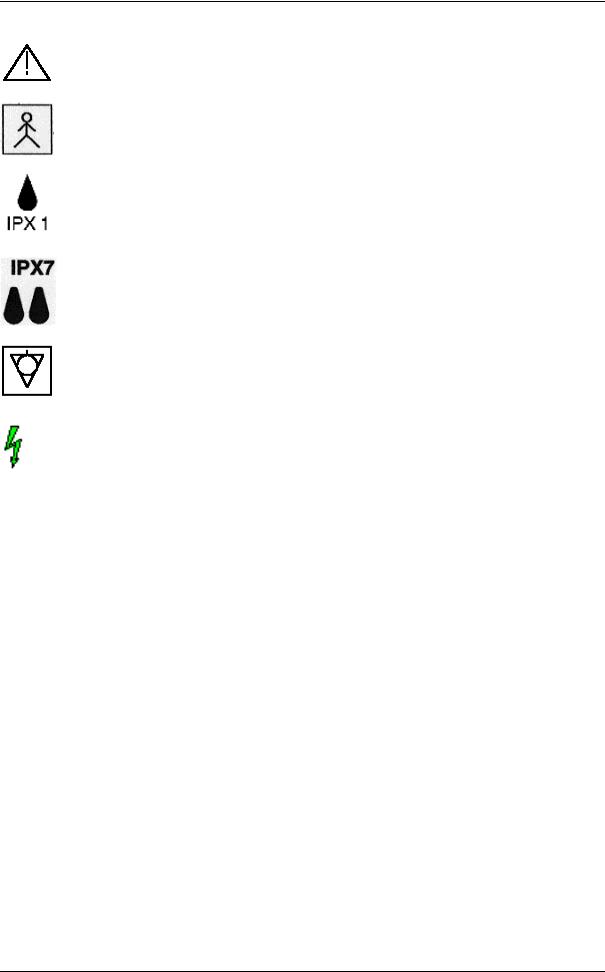
2.3Symbols used
Some symbols used with electrical medical equipment have been accepted as standard by IEC. They serve for marking of connection, accessories, and as warnings.
Mains switch ON acc. to IEC 417 5007
Mains switch OFF acc. to IEC 417 5008
Standby switch of the System. Location see: System Configuration acc. to IEC 417 5009
ON switch of the isolation transformer for auxiliary devices acc. to IEC 417 5264
OFF switch of the isolation transformer for auxiliary devices acc. to IEC 417 5265
Voluson® 730 - Instruction Manual
105838 Rev. 3 |
2-3 |
Safety
CAUTION! Review user manual for proper operation! (Improper use may cause damage.)
Insulated patient application part acc. to EN60 601-1(Type BF)
IPX1 Protection against dripping water.
IPX7 Protection against the effects of immersion.
Potential equilibrium connection (rear panel)
Dangerous electric voltage
Pull the mains plug before opening the unit!
Voluson® 730 - Instruction Manual
2-4 |
105838 Rev. 3 |

Safety
2.4Remarks for safe Use
•Get acquainted with the transducers and the ultrasound system: read the user manual thoroughly!
•Follow these safety instructions as well as the clinically adopted precautions and measures for hygiene.
•The manufacturer is not liable for damage caused by improper or inexpert use of the device!
•Any ultrasound transducers - irrespective of system and design - are sensitive to shock and shall be treated with care. Pay attention to cracks which may allow conductive fluids to leak in.
•Authorized personnel shall only perform any type of repair. Never attempt to open a transducer or transducer connector. This leads to a loss of guarantee!
•Avoid kinking, bending or twisting of probe cables and take care to guard them against mechanical stress (e.g., wheels or heels).
•The probes must not be exposed to mechanical shock (e.g., by dropping). Any damage caused in this manner invalidates warranty.
•Have the scanner system and the transducers regularly checked (for faulty cables, housing, etc.) by authorized personnel!
•Damage to transducer or cable may lead to a safety hazard, therefore have them repaired immediately!
•Before plugging in or unplugging a transducer, activate the "FREEZE" mode!
•A specialist acquainted with the handling and use of the system shall perform installation and first switch-on and check-up of the system.
•The user must have read and understood the user manual.
The system must only be operated by trained and qualified personnel.
•For safety reasons, avoid handling fluids in the vicinity of the system. Fluids leaking into the disk drive can damage the drive. Never remove the storage shelf above the probe connectors; it helps to protect the unit from fluids.
•Do not put your hand under the control console when moving it: Danger of injuries!
•Trolley: never move the unit with blocked wheels, but block the wheels in the proximity of stairs and ramps.
•Place the unit always on horizontal ground and block the front wheels: Danger of tipping over and rolling away.
•In transporting the unit, raise the footrest: Danger of injuries!
•The user manual must always be with the scanner system. It is the user's duty to ensure this!
•Only probes conforming to type BF requirements may be used with the VOLUSON® 730.
Voluson® 730 - Instruction Manual
105838 Rev. 3 |
2-5 |

Safety
See the probe's label. In case of doubt ask authorized service personnel.
•The Voluson® 730 system has been tested for EMC and is compliance with
EN 55011:1991 group 1 class A (CISPR 11:1997 amendment 1:1999) and EN 60601-1-2:1993. The Voluson® 730 system is approved for use in a residential district. It is expected that
the user has medical experience and is well informed with the user manual.
•Mains power quality should be that of a typical commercial and/or hospital environment.
If the user requires continued operation during power mains interruptions, it is recommended that the system be powered from an uninterruptable power source (UPS).
There have been reports of severe allergic reactions to medical devices containing latex (natural rubber). Operators are advised to identify latexsensitive patients and be prepared to treat allergic reactions promptly. Refer to FDA Medical Alert MDA91-1.
2.5Environmental Conditions for Operation
Temperature: |
10°C to 40°C resp. 50°F to 104°F |
Humidity: |
30% to 80% RH, no condensation |
Barometric pressure: |
700 to 1060 hPa |
CAUTION ! Do not operate the system in the vicinity of a source of heat, of strong electric or magnetic fields (close to a transformer), or near instruments generating highfrequency signals, such as HF surgery.
These can affect the ultrasound images adversely.
CAUTION ! In the event the equipment has been brought from cold environment (stock room, airfreight) into a warm room, allow several hours for temperature balance and passing of condensation humidity before switching on the first time.
2.6Instruction for Use
This equipment has been tested and found to comply with the limits for medical devices in IEC 60601- 1-2:1994. These limits are designed to provide reasonable protection against harmful interference in a typical medical installation.
This equipment generates, uses and can radiate radio frequency energy and, if not installed and used in accordance with the instructions, may cause harmful interference to other devices in the vicinity. However, there is no guarantee that interference will not occur in a particular installation.
If this equipment does cause harmful interference to other devices, which can be determined by turning the equipment off and on, the user is encouraged to try to correct the interference by one or more of the following measures:
-Reorient or relocate the receiving device.
-Increase the separation between the equipments.
-Connect the equipment to an outlet on a circuit different from that to which the other device(s) are connected.
-Consult the manufacturer or field service technician for help.
Voluson® 730 - Instruction Manual
2-6 |
105838 Rev. 3 |

Safety
2.7Biopsy Lines
To achieve best possible accuracy of the display of the needle way, the biopsy lines have to be programmed for each transducer.
review: To program a Biopsy Line (chapter 19.1) of the Basic User Manual for Voluson® 730.
WARNINGS !
•The biopsy lines must be programmed once by the service personnel or by the user. The procedure must be repeated if probes and /or biopsy guides are exchanged.
•Before performing a biopsy, make sure that the displayed biopsy line coincides with the needle track (check in a bowl filled with approx. 47°C warm water!).
•The needle used for this alignment verification must not be used for the actual procedure. Always use a straight, new and sterile needle for each biopsy procedure.
2.8ECG-preamplifier (MAN)
The ECG preamplifier type MAN is an option of the ultrasound scanner unit, used to obtain an ECG signal to mark the systolic and end-diastolic moments in M mode and Doppler evaluations.
WARNINGS !
•The MAN is not intended for ECG diagnosis. It must not be used for an intra-operative application of the heart.
•Monitor: Not for use as a cardiac monitor.
•Only the patient cable supplied by GE Medical Systems - Kretztechnik, and only recommended electrodes must be used.
•Take care that neither bare parts of one of the three electrodes nor the patient comes into contact with conductive parts (e.g., metal parts of the examination bed, trolley, or similar).
•If the use of a HF surgical unit with simultaneously connected ECG electrodes becomes necessary, a large distance of ECG electrodes from the surgical field and a perfect position of the neutral electrode of the HF surgical unit must be observed (avoiding burning risk).
•If the use of a defibrillator becomes necessary, there must be no ECG adhesive electrodes and no conductive paste between the correct positions of the defibrillator plates (avoiding current bridge; the signal input of the ECG preamplifier is defibrillator-safe).
For further details and information’s please review: MAN ECG preamplifier (chapter 21) of the Basic User Manual for Voluson® 730.
Voluson® 730 - Instruction Manual
105838 Rev. 3 |
2-7 |

Safety
2.9Cleaning and Maintenance
Daily cleaning of the scanner, the probes and the probe holders from coupling gel, mineral oil etc. is recommended, wet cloth and soap are allowed.
CAUTION ! Before cleaning the scanner switch it off. Do not use disinfection spray nor gas disinfection. Electric parts must be protected from drip water. Keep the touchpanel screen clean. Dust and parts on the frame can cause irregular function!
Check the mains cable, transducer cables, plugs and sockets regularly.
Have the system checked and serviced in regular intervals (once per year) by authorized service personnel. In case of total failure first check if mains voltage is present.
Mentioning any observations or failure symptoms to the service engineers is helpful.
2.10 Safety Test
Scan time limits: Acc. to respective national regulations, and acc. to the manufacturer recommendations for the medical-technical unit.
Range:
a)Visual inspection:
Housing, connection, operating elements, display facilities, labels, accessories, user manual.
b)Functional test:
Checking of functions (acc. to user manual), check also modular combinations and common operability of system and accessories.
c)Electric test:
Checking of the electric safety of system combinations acc. to VDE 0751 or respective national regulations.
For safety reasons, avoid handling fluids in the vicinity of the system.
Voluson® 730 - Instruction Manual
2-8 |
105838 Rev. 3 |

Safety
2.11 Manufacturer Responsibility
The manufacturer, assembler, importer or installer considers himself/herself responsible regarding safety, reliability and performance of the instrument under the following conditions:
-when assembling the system, when performing add-ones, when new settings or modifications or repairs were performed by personnel authorized by him/her,
-also that the local electric installation complies to the national regulations, and that the equipment is only used according to the User Manual.
2.12 Service Documents
The Service Manual supplies block diagrams, lists of spare parts, descriptions, adjustment instructions or similar information which help adequately qualified technical personnel in repairing those parts of the instrument which have been defined repairable by the manufacturer.
2.13 Basic interaction between Ultrasound and Matter
2.13.1Bioeffects
"Diagnostic ultrasound has been in use since the late 1950s. Given its known benefits and recognized efficacy for medical diagnosis, including use during human pregnancy, the American Institute of Ultrasound in Medicine herein addresses the clinical safety of such use:
No confirmed biological effects on patients or instrument operators caused by exposure at intensities typical of present diagnostic ultrasound instruments have ever been reported. Although they indicate that the benefits to patients of the prudent use of diagnostic ultrasound outweigh the risks, if any, that may be present."
Reference: |
Bioeffects considerations for the safety of Diagnostic Ultrasound - Journal of |
|
Ultrasound in Medicine, Vol.7, Number 9 (supplement) - American Institute of |
|
Ultrasound in Medicine, Bioeffects Committee. |
Please note: |
Prudent use means that the ultrasound machine is to be used by the operator in |
|
accordance with the ALARA principle, i.e. keep the power levels and the exposure |
|
time AS LOW AS REASONABLY ACHIEVABLE. |
An ultrasound bioeffect is any biological mechanism or process, which is produced, triggered or catalyzed by exposure to ultrasound.
One can differentiate two known mechanisms for the development of bioeffects when humans are exposed to ultrasound: the thermal effect of ultrasound and the cavitation.
With humans no harmful bioeffects due to exposure to diagnostic ultrasound have been noticed.
Voluson® 730 - Instruction Manual
105838 Rev. 3 |
2-9 |

Safety
The rise in tissue-temperature under the influence of ultrasound energy is called thermal effect.
The level of the temperature rise depends mainly on the following parameters: the irradiated quantity of energy, the surface of exposure and the thermal characteristics of the tissue. Regarding the thermodynamics, the AIUM-report comes to the following conclusions:
•When only the temperature criteria is considered, an exposure to diagnostic ultrasound, leading to a rise in temperature of 1°C above the normal physiological value can be made without limitations in clinical examinations.
•With fetal use a temperature rise in situ beyond 41°C is considered dangerous; the risk of harming the fetus is increased with the duration of this temperature rise.
•For fetal use the following intensities are considered to be safe:
•SATA-intensity (in situ) below 200 mW/cm2 with beam widths of less than 11 wavelengths.
•SATA-intensity (in situ) below 300 mW/cm2 with beam widths of less than 8 wavelengths.
Note that the thermal model of the AIUM does not take into account the influence of tissue blood circulation.
Cavitation concerns the reaction of gasor vapor bubbles or gasor vapor accumulations present in tissue or liquids. Two types of cavitation - transient and stable - have been described and investigated in in-vitro and animal tests (Flynn HG, Physics of Acoustic Cavitation in Liquids, in Physical Acoustics: Principals and Methods, edited by Mason, WP, Academic Press, New York, 1964, Vol. I/B, Chap. 9, pp. 57-172).
Transient cavitation means dilatation and quick collapsing of a bubble as a reaction to one or more ultrasound pulse beams. This quick collapse can lead to locally limited (in micrometer range) high temperatures and pressures.
Stable cavitation concerns the repeated oscillation of a bubble. This bubble oscillation can have effects on neighboring cells, especially due to transverse action acting on its membrane and due to disturbance of the contained cytoplasma. Amplitude and frequency of the bubble oscillation are dependent on the bubble size at the beginning and resonance frequency characteristics as well as on frequency and pressure of the impinging ultrasound. With tissue of mammals the scientists came to contradictory results regarding the ability to produce cavitation. This is possibly due to differences in the occurrence of cavitation germs (bubbles). Very little is known about the factors determining the presence or absence of micro bubbles, their chemical consistence and visco-elastic characteristics. The results of cavitation tests also depend on ambient pressure, on the acoustic energy and the pressure level. With the output power used in diagnostic ultrasound no cavitation was observed in vivo.
The AIUM-report reaches the following conclusions regarding cavitation:
•Cavitation can occur with short pulses and produces potentially harmful biological effects.
•A peak pressure of 10 MPa (3300 W/cm2) can lead to cavitation with mammals.
With the limited data available it is not possible to specify threshold values for the pressure amplitude at which - when using diagnostically relevant pulse lengths and pulse repetition frequencies - cavitation occurs with mammals.
Some scientists observed that the peak rarefaction pressure (pr) of the transmitted disturbance is related closer to occurrence of cavitation than to the overall measured peak pressure (due to compression plus rarefaction). Other examinations showed that the peak rarefaction pressure of the basic oscillation component of the disturbance could be among the three mentioned parameters the most closely related to the cavitation.
Voluson® 730 - Instruction Manual
2-10 |
105838 Rev. 3 |
Safety
The following results are contained in the AIUM-report too:
•Other acting mechanisms - no other acting mechanisms for bioeffects are known, that are caused by exposure to diagnostic ultrasound.
•Epidemiology - in more than 25 years of extensive clinical ultrasound application no harmful effects due to exposure to diagnostic ultrasound have become known.
•Bioeffects in vivo with mammals - no significant bioeffects in vivo independently confirmed could be determined under the following conditions:
•Unfocussed exposure with an SPTA-intensity of less than 100 mW/cm2 in an exposure period of less than 500 seconds (measured in water).
•Focused exposure with an SPTA-intensity of less than 1 W/cm2 in an exposure period of less than 50 seconds (measured in water).
•Product from intensity (measured in water) and time of exposure less than 50 joule/cm2.
2.13.2Intensities Measured in Water and recalculated In Situ
All intensity parameters are determined by measurement in water. As water does not absorb the acoustic energy, these measurements in water represent the most unfavorable value. In biological tissue however the acoustic intensity is absorbed. The "real" value in a given position depends on the amount and type of tissue through which the ultrasound beam passes and on the ultrasound frequency. The value in tissue (in situ) can be approximately determined with the following formula:
in situ = water [ e -(0.23dlf) ]
Whereas: in situ |
= |
value in situ |
water |
= |
value in water |
e |
= |
2.7183 |
d |
= |
attenuation coefficient |
l |
= distance from skin surface to measuring depth (cm) |
|
f |
= mean frequency of combination probe/system/operation |
|
|
|
mode (MHz) |
tissue |
|
d (dB/cm/MHz) |
brain |
|
0.53 |
heart |
|
0.66 |
kidney |
|
0.79 |
liver |
|
0.43 |
muscle |
|
0.55 |
As the ultrasound generally crosses tissue layers of different thickness and different types on its way through the body during an examination, it is very difficult to estimate the real intensity in situ.
For reports generally an impedance coefficient of 0.3 dB/cm/MHz is assumed. The value in situ that is generally indicated in reports is calculated according to the following formula:
in situ (recalculated ) = water [e -(0.69lf) ]
As this value must not be considered as the real intensity in situ, the term "recalculated" is used hereunder.
Voluson® 730 - Instruction Manual
105838 Rev. 3 |
2-11 |

Safety
In some cases the max. Recalculated value and the max. Value in water do not occur under the same operating conditions. Therefore the max. Values in water and recalculated max. Values mentioned in reports may not be related according to the above mentioned formula.
For example: An array probe with multiple focusing, whose max. Intensity values in water are lying in the deepest focal zone; for this zone, however, the smallest recalculating factor is valid. With the same probe the highest recalculated intensity can be lying in one of the focal zones closest to the surface.
The FDA has laid down limits for the max. recalculated intensity values (see following section). Therefore the recalculated intensities are brought to the highest possible value with the help of the system controls when the output power is tested. Under all operating conditions the point of the max. Recalculated intensity can be closer to the probe than the point of the max. Intensity in water; it will never be further away from the transducer.
2.13.3Derivation and Meaning of the thermal and mechanical Indices
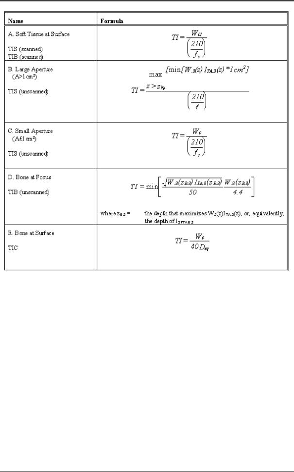
The Standard for real-time Display of Thermal and Mechanical Acoustic Output Indices on Diagnostic Ultrasound Equipment, ©1992 by the American Institute of Ultrasound in Medicine (AIUM) and the National Electrical Manufacturers Association (NEMA), defines Thermal and Mechanical Indices as follows. Please refer to this standard to get further information on this matter.
Thermal Index (TI) is a quantity related to calculated or estimated temperature rise under certain defined assumptions. The Thermal Index is the ratio of total acoustic power to the power required to raise tissue temperature by 1°C under defined assumptions. In the calculation of all Thermal Indices in the "Standard for real-time Display of Thermal and Mechanical Acoustic Output Indices on Diagnostic Ultrasound Equipment", of the AIUM and NEMA, the average ultrasonic attenuation is assumed to be 0.3 dB/cm-MHz along the beam axis in the body.
Soft Tissue Thermal Index (TIS) is the Thermal Index related to soft tissues.
Bone Thermal Index (TIB) is the thermal index for applications, such as fetal (second and third trimester) or neonatal cephalic (through the fontanel), in which the ultrasound beam passes through soft tissue and a focal region is the immediate vicinity of bone.
Cranial Bone Thermal Index (TIC) is the Thermal Index for applications, such as pediatric and adult cranial applications, in which the ultrasound beam passes through bone near the beam entrance into the body.
Mechanical Index (MI) formula is the spatial-peak value of the peak rare factional pressure, derated by 0.3 dB/cm-MHz at each point along the beam axis, divided by the square root of the center frequency. To make the MI unitless, the right-hand side of the equation below is multiplied by [(1
MHz)0.5/(1 Mpa)].
Scanned mode (auto-scanning) is the electronic or mechanical steering of successive ultrasonic pulses or series of pulses, through at least two dimensions.
Unscanned mode (nonautoscanning) is the emission of ultrasonic pulses in a single direction, where scanning in more than one direction would require moving the transducer assembly manually.
Voluson® 730 - Instruction Manual
2-12 |
105838 Rev. 3 |
Safety
Voluson® 730 - Instruction Manual
105838 Rev. 3 |
2-13 |

Safety
Reference: |
Standard for Real Time Display of Thermal and Mechanical Acoustic Output Indices |
|
on Diagnostic Ultrasound Equipment - |
|
©1992 by American Institute of Ultrasound in Medicine (AIUM) and National |
|
Electrical Manufacturers Association (NEMA). |
Voluson® 730 - Instruction Manual
2-14 |
105838 Rev. 3 |

Safety
2.13.4FDA-Limits for Acoustic Output and Bioeffects
The American Food and Drug Administration (FDA) has laid down maximum values in situ * (recalculated) for different clinical applications, which are valid independent of the operation mode (2D, M-Mode, Doppler). These values are not defined on the basis of the ultrasound bioeffects, but are based on the output power of instruments, that were manufactured prior to the modification of FDARegulations 1976. The enclosed acoustic output tables contain the recalculated limits as laid down by FDA and the values mentioned in the AIUM-report.
•Contains the recalculated limits as laid down by FDA and the values mentioned in the AIUMreport.
•No limits were laid down by the FDA for measurements in water.
2.13.5Summary
1.Presently limits for the output power are laid down neither by the FDA, nor by AIUM-report of the Bioeffects Committee. Thermal models in development in 1991 include the output power.
2.The AIUM report contains no specific conclusions regarding an ISPPA within the FDA limits.
3.The ISPTA is a relevant parameter regarding bioeffects. The FDA limits and the values recommended by the AIUM concerning bioeffects are compatible. In some of the thermal model in development in 1991 there is an ISPTA factor.
4.The AIUM report does not contain any specific conclusions regarding an IMAX within the FDA limits. Presently (1991) the FDA considers to renounce to the IMAX as a parameter of the output power to be reported.
5.Presently the FDA considers a cavitation parameter the mechanical index MI which is based on Pr. The limit for MI is 1.9.
6.The FDA considers ISATA as a relevant parameter regarding bioeffects. The FDA limits for the ISATA are not based on bioeffects; they are rather based on the output power before the regulation modification 1976.
7.No limits for the measurement in water were laid down.
8.In some cases the tissue can be exposed to sound and intensity values that are higher than those given (recalculated) for in situ. In these cases the reported values in situ do not represent the worst case of exposure. But this case occurs only if the tissue has an attenuation coefficient below 0.3 dB/cm/MHz, e.g. with a long way through liquids and a short way through tissue. In such cases an output power of less than 100% is recommended; therefore the examiner should reduce the power in order to reduce sound intensity impinging on the tissue.
Voluson® 730 - Instruction Manual
105838 Rev. 3 |
2-15 |

Safety
2.13.6Display Accuracy of the Indices
On the right side of the monitor display the thermal and mechanical indices are displayed. While scanning, notice the index numbers you are using and which controls affect the readings.
Try to keep the index numbers as low as you can, while maintaining diagnostic information within the image. This is particularly important when scanning the fetus. The display accuracy of the mechanical index and all thermal indices is 0.1. Values below 0.4 are not displayed.
Reference: |
"Standard for real-time Display of Thermal and Mechanical Acoustic Output Indices |
|
on Diagnostic Ultrasound Equipment", AIUM/NEMA, Washington, DC, 1992. |
2.13.7Recommendation to use and for the Need for following the ALARA Principle
The AIUM publication "Medical Ultrasound Safety", published 1994 by the AIUM says the following about the ALARA principle:
The ALARA principle "stands for 'As Low As Reasonably Achievable'. Following the ALARA principle means to keep the total ultrasound exposure as low as reasonably achievable, while optimizing diagnostic information.
With the new ultrasound equipment, the output display lets us determine the exposure level in terms of the potential for bioeffects...", and "Because the threshold of diagnostic ultrasound bioeffects is undetermined, it becomes our responsibility to control the total exposure to the patient. Controlling the total exposure depends on output level and exposure time. The output level required for an exam depends on the patient and on the clinical need. Not all diagnostic exams can be performed at very low levels. In fact, using too low levels may result in poor data and the need to repeat the examination. Using too high a level may not increase the quality of the information, but it will expose the patient to unneeded ultrasound energy."
"Ultimately, the exposure time depends on the person conducting the exam. Primarily, it's our training, education, and experience that determine how quickly we can obtain a useful image, and thus, the length of the exam and the amount of exposure. So, the question is 'How much time do we need to obtain the desired diagnostic information?'" The AIUM also lists some other factors that might affect the length of exposure time, like if there is a moving or a stationary beam, what kind of transducer is chosen, what is the body characteristic of the patient, if the operator is understanding the controls of the system, and how they affect output levels, whether it's continuous or pulsed, or color flow Doppler.
"To achieve ALARA, we need a thorough knowledge of the imaging mode, transducer capabilities, system setup, and operator scanning techniques."
GE Medical Systems-Kretztechnik Ultrasound therefore recommends careful studying of the system's manual to become familiar with the operating controls and output display of the system as well as with following the ALARA principle. This might decrease the risk of any potential biological hazard caused by ultrasound exposure during an examination!
Reference: |
Medical Ultrasound Safety, AIUM 1994 |
|
AIUM Executive Office |
|
14750 Sweitzer Lane, |
|
Suite 100, Laurel, MD 20707-5906, USA |
Please note that the above referenced AIUM publication is attached to this manual.
Voluson® 730 - Instruction Manual
2-16 |
105838 Rev. 3 |

Safety
2.13.8Notes for Acoustic Output Tables for Track 3
Operating Conditions: means the adjustment of the scan parameters on the ultrasound console
MI: |
is the Mechanical Index in an auto-scanning mode. |
TISscan: |
is the Soft Tissue Thermal Index in an auto-scanning mode. |
TISnon-scan: |
is the Soft Tissue Thermal Index in a non-auto scanning mode. |
TIB: |
is the Bone Thermal Index. |
TIC: |
is the Cranial Thermal Index. |
Aaprt: |
is the area of the active aperture (square centimeters). |
pr.3: |
is the derated Peak Rare factional Pressure (megapascals). |
W0: |
is the ultrasonic power, except for TISscan, in which case it is the ultrasonic power |
|
passing through a one-centimeter window (mill watts). |
W.3(z1): |
is the derated ultrasonic power at axial distance z1. |
ISPTA.3(z1): |
is the derated spatial-peak, temporal-average intensity at axial distance z1 (mill watts |
|
per square centimeters). |
z1: |
is the axial distance corresponding to the location of max[min(W.3(z).ITA.3(z) * 1 |
|
cm2)], where z³zbp (millimeters). |
zbp: |
is 1.69(Aaprt)1/2. |
For MI, zsp: |
is the axial distance at which pr.3 is measured; for TIB, zsp is the axial distance at |
|
which TIB is a maximum (i.e. zsp = zb.3) (millimeters). |
deq(z): |
is the equivalent beam diameter as a function of axial distance z, and is equal to |
|
[(4/p)(W0/ITA(z))]1/2, where ITA(z) is the temporal-average intensity as a function |
|
of z (millimeters). |
fc: |
is the center frequency (megahertz). |
EBD: |
are the entrance beam dimensions for the azimuthal and elevational planes |
1 - 12 |
(millimeters). |
PD: |
is the pulse duration (microseconds). |
PRF: |
is the pulse repetition frequency (kilohertz). |
Voluson® 730 - Instruction Manual
2-17

Safety
pr at Pllmax: |
is the peak rare factional pressure at the point where the free-field, spatial peak pulse |
|
intensity integral is a maximum (megapascals). (See section 6 of the Standard for |
|
Real-Time Display of Thermal and Mechanical Indices on Diagnostic Ultrasound |
|
Equipment, entitled "Measurement Methodology for Mechanical and Thermal |
|
Indices", § 6.2.6.1.) |
FL: |
is the focal length, or azimuthal and elevational lengths, if different (millimeters). |
ROC: |
is the radius of curvature (millimeters). |
deq at Pllmax: |
is the equivalent beam diameter at the point where the free-field, spatial-peak pulse |
|
intensity integral is a maximum (millimeters). (See Section 6 of the Standard for |
|
Real-Time Display of Thermal and Mechanical Indices on Diagnostic Ultrasound |
|
Equipment, entitled "Measurement Methodology for Mechanical and Thermal |
|
Indices", § 6.2.6.1.). |
Reference: Revised 510(k) Diagnostic Ultrasound Guidance for 1993; CDRH, FDA; Feb. 17, 1993
2.13.9Acoustic Measurement Uncertainties
ISPTA: |
± |
16% |
MI: |
± |
10% |
ISPPA: |
± |
17% |
TIB: |
± |
35% |
Pr: |
± |
10% |
TIS: |
± |
19% |
Fc: |
± |
1% |
TIC |
± |
21% |
W:± 19%
2.13.10Acoustic Output Tables
Acoustic Output Tables (acc. to Track 3 as demanded in the Revised 510(k). Diagnostic Ultrasound Guidance for 1993; CDRH, FDA; Feb. 17, 1993), respectively guidance Information for
Manufacturers Seeking Marketing Clearance of Diagnostic Ultrasound Systems and Transducers issued on September 30, 1997:
Please read the safety section for the complete explanation of the acoustic output in the User’s Manual of the respective probes.
Voluson® 730 - Instruction Manual
2-18 |
105838 Rev. 3 |

Safety
2.14 3D-Resolution and Sensitivity
•All resolution and sensitivity claims are based on phantom testing only. These claims do not directly correspond to or imply clinical performance.
NOTE: All system claims made are based on testing done with Dr. Madsen's phantom.
DESCRIPTION OF Dr. MADSEN'S PHANTOM
The phantom is designed and constructed by Ernest L. Madsen, Ph. D., in the Department of Medical Physics at the University of Wisconsin Medical School.
This 3D ultrasound phantom contains two sets of spherical targets. All spherical targets in the same set
have coplanar centers and the same diameter and identical contrastsa over the total depth of 15cm. The center-to-center separation between adjacent spheres is 0.5cm in the vertical plane and 1.5cm in the horizontal plane.
Specifications: |
Dimensions (h x w x d): |
20cm x 18cm x 8cm |
|
Housing Material: |
Acrylic |
|
Wall Thickness: |
1 cm |
|
Scan Surfaces: |
1 |
|
Scan Surface Material/Dimension: |
Saran Wrap 2.5mm |
|
Scan Surfaces Dimensions: |
15cm x 5cm |
We can reconstruct high contrast spherical images in the 3 to 5 mm diameter range in 3 orthogonal planes only for targets that have negative contrast of at least -17dB (for 3mm and 4mm) / -14dB (for 5mm) backscatter relative to the background level (based on Dr. Madsen's phantom).
This is because the -17dB / -14dB contrast levels were the only high contrast levels tested.
•We can detect large targets, i.e., spheres of 3, 4, and 5 mm in diameter.
This pertains only high contrast large targets (i.e., contrast of -17dB / -14dB or higher).
•We can detect large targets, i.e., sphere of 5 mm or larger in diameter. This pertains only low contrast large targets (i.e., contrast of at least +3dB).
NOTE: The resolution in orthogonal, reconstructed plane is considerably lower than that of the primary scan plane. The system resolution is particularly lower for low contrast targets in the reconstructed, orthogonal plane.
Significant system artifacts may exist in the orthogonal plane parallel to the face of the probe.
a Defining the backscatter coefficient of the material forming the lesions to be Bl and that the background material to be Bbg, the contrast is defined (in dB) as 10 log10 (Bl / Bbg).
Voluson® 730 - Instruction Manual
105838 Rev. 3 |
2-19 |
 Loading...