


 Loading...
Technical Publication
Venue 50
Basic Service Manual
Direction Number: 5447566-100 English
Rev. 7
All Material Copyright © 2013-2015 by General Electric Company Inc. All Rights Reserved.

Product Information
This Manual covers the software version of R4.x.x for Venue 50 ultrasound system.
GE
P.O. Box 414, Milwaukee, Wisconsin 53201 U.S.A.
(Asia, Pacific, Latin America, North America)
GE Ultraschall Deutschland GmbH & Co. KG
Beethovenstrasse 239
Postfach 11 05 60
D-42655 Solingen GERMANY
TEL: 49 212.28.02.208; FAX: 49 212.28.02.431

Revision history
|
|
Revision History |
|
|
|
|
|
|
Date |
|
|
Revision |
(YYYY/MM/DD) |
|
Reason for change |
|
|
|
|
Rev. 1 |
2013/02/25 |
|
Initial Release. |
|
|
|
|
Rev. 2 |
2013/10/09 |
|
Add FRU replacement procedures and update repair parts |
|
|
|
list. |
|
|
|
|
Rev. 3 |
2013/11/26 |
|
Update FRU replacement procedures and repair parts list. |
|
|
|
|
Rev. 4 |
2014/04/11 |
|
Update remote service function. |
|
|
|
|
Rev. 5 |
2014/05/28 |
|
Update the spare part list. |
|
|
|
|
Rev. 6 |
2014/07/04 |
|
Add Power Module Information. |
|
|
|
|
Rev. 7 |
2015/05/13 |
|
Update the spare part list. |
|
|
|
|
List of Effected Pages (LOEP)
Pages |
Revision |
Pages |
Revision |
|
|
|
|
Front |
Rev. 7 |
Chapter 6 |
Rev. 7 |
|
|
|
|
Front matter |
Rev. 7 |
Chapter 7 |
Rev. 7 |
|
|
|
|
TOC |
Rev. 7 |
Chapter 8 |
Rev. 7 |
|
|
|
|
Chapter 1 |
Rev. 7 |
Chapter 9 |
Rev. 7 |
|
|
|
|
Chapter 2 |
Rev. 7 |
Chapter 10 |
Rev. 7 |
|
|
|
|
Chapter 3 |
Rev. 7 |
Index |
Rev. 7 |
|
|
|
|
Chapter 4 |
Rev. 7 |
Rear Cover |
Rev. 7 |
|
|
|
|
Chapter 5 |
Rev. 7 |
|
|
|
|
|
|
Please verify that you are using the latest revision of this document. Information pertaining to this document is maintained on MyWorkshop/ePDM (GE electronic Product Data Management). If you need to know the latest revision, contact your distributor, local GE Sales Representative or in the USA call the GE Ultrasound Clinical Answer Center at 1 800 682 5327 or 1 262 524 5698.
Venue 50 – Basic Service Manual |
i-1 |
5447566-100 English Rev. 7 |
|
Important Precautions
Translation policy
i-2 |
Venue 50 – Basic Service Manual |
|
5447566-100 English Rev. 7 |

Venue 50 – Basic Service Manual |
i-3 |
5447566-100 English Rev. 7 |
|
i-4 |
Venue 50 – Basic Service Manual |
|
5447566-100 English Rev. 7 |
Venue 50 – Basic Service Manual |
i-5 |
5447566-100 English Rev. 7 |
|
i-6 |
Venue 50 – Basic Service Manual |
|
5447566-100 English Rev. 7 |
Venue 50 – Basic Service Manual |
i-7 |
5447566-100 English Rev. 7 |
|
i-8 |
Venue 50 – Basic Service Manual |
|
5447566-100 English Rev. 7 |
Venue 50 – Basic Service Manual |
i-9 |
5447566-100 English Rev. 7 |
|
i-10 |
Venue 50 – Basic Service Manual |
|
5447566-100 English Rev. 7 |

Damage in Transportation
All packages should be closely examined at time of delivery. If damage is apparent, write “Damage In Shipment” on ALL copies of the freight or express bill BEFORE delivery is accepted or “signed for” by a GE representative or hospital receiving agent. Whether noted or concealed, damage MUST be reported to the carrier immediately upon discovery, or in any event, within 14 days after receipt, and the contents and containers held for inspection by the carrier. A transportation company will not pay a claim for damage if an inspection is not requested within this 14 day period.
Certified Electrical Contractor Statement - For USA Only
All electrical Installations that are preliminary to positioning of the equipment at the site prepared for the equipment shall be performed by licensed electrical contractors. Other connections between pieces of electrical equipment, calibrations and testing shall be performed by qualified GE personnel. In performing all electrical work on these products, GE will use its own specially trained field engineers. All of GE’s electrical work on these products will comply with the requirements of the applicable electrical codes.
The purchaser of GE equipment shall only utilize qualified personnel (i.e., GE’s field engineers, personnel of third-party service companies with equivalent training, or licensed electricians) to perform electrical servicing on the equipment.
Venue 50 – Basic Service Manual |
i-11 |
5447566-100 English Rev. 7 |
|

Omission and Errors
If there are any omissions, errors or suggestions for improving this documentation, contact the GE Global Documentation Group with specific information listing the system type, manual title, part number, revision number, page number and suggestion details.
Mail the GE Medical Systems (China) Co., Ltd. information to: No. 19 Changjiang Road
Wuxi National Hi-Tech Dev. Zone Jiangsu
P.R.China 214028
GE employees should use TrackWise to report service documentation issues.
These issues will then be in the internal problem reporting tool and communicated to the writer.
i-12 |
Venue 50 – Basic Service Manual |
|
5447566-100 English Rev. 7 |

Service Safety Considerations
DANGER
WARNING
DANGEROUS VOLTAGES, CAPABLE OF CAUSING DEATH, ARE PRESENT IN THIS EQUIPMENT. USE EXTREME CAUTION WHEN HANDLING, TESTING AND ADJUSTING.
Use all Personal Protection Equipment (PPE) such as gloves, safety shoes, safety glasses, and kneeling pad, to reduce the risk of injury.
For a complete review of all safety requirements, refer to Chapter 1 in the Service Manual.
Venue 50 – Basic Service Manual |
i-13 |
5447566-100 English Rev. 7 |
|

Legal Notes
The contents of this publication may not be copied or duplicated in any form, in whole or in part, without prior written permission of GE.
GE may revise this publication from time to time without written notice.
Trademarks
All products and their name brands are trademarks of their respective holders.
Copyrights
All Material Copyright © 2013-2014 by
General Electric Company Inc. All Rights Reserved.
i-14 |
Venue 50 – Basic Service Manual |
|
5447566-100 English Rev. 7 |

Table of Contents
Translation policy - - - - - - - - - - - - - - - - - - - - - - - - - - - - - - - - - - - - - - - - i-2 Damage in Transportation - - - - - - - - - - - - - - - - - - - - - - - - - - - - - - - - - i-11 Certified Electrical Contractor Statement - For USA Only - - - - - - - - - - - i-11 Omission and Errors - - - - - - - - - - - - - - - - - - - - - - - - - - - - - - - - - - - - - i-12 Service Safety Considerations - - - - - - - - - - - - - - - - - - - - - - - - - - - - - - i-13 Legal Notes - - - - - - - - - - - - - - - - - - - - - - - - - - - - - - - - - - - - - - - - - - - i-14 Trademarks - - - - - - - - - - - - - - - - - - - - - - - - - - - - - - - - - - - - - - - - - - - i-14
Copyrights - - - - - - - - - - - - - - - - - - - - - - - - - - - - - - - - - - - - - - - - - - - - i-14
Table of Contents Chapter 1 — Introduction
Overview
Contents in This Chapter - - - - - - - - - - - - - - - - - - - - - - - - - - - - - - - - - - 1-2
Manual Overview
Contents in This Manual - - - - - - - - - - - - - - - - - - - - - - - - - - - - - - - - - - 1-3 Typical Users of the Proprietary Service Manual - - - - - - - - - - - - - - - - - 1-4 Venue 50 models covered by this manual - - - - - - - - - - - - - - - - - - - - - - 1-5
Important Conventions
Conventions used in book - - - - - - - - - - - - - - - - - - - - - - - - - - - - - - - - - 1-6 Standard hazard icons - - - - - - - - - - - - - - - - - - - - - - - - - - - - - - - - - - - 1-8
Product Icons
Label Icon Description- - - - - - - - - - - - - - - - - - - - - - - - - - - - - - - - - - - 1-10 Labels Locations- - - - - - - - - - - - - - - - - - - - - - - - - - - - - - - - - - - - - - - 1-14
Safety Considerations
Contents in this section - - - - - - - - - - - - - - - - - - - - - - - - - - - - - - - - - - 1-15 Introduction - - - - - - - - - - - - - - - - - - - - - - - - - - - - - - - - - - - - - - - - - - 1-15 Human Safety - - - - - - - - - - - - - - - - - - - - - - - - - - - - - - - - - - - - - - - - 1-16 Mechanical safety - - - - - - - - - - - - - - - - - - - - - - - - - - - - - - - - - - - - - - 1-18 Electrical safety - - - - - - - - - - - - - - - - - - - - - - - - - - - - - - - - - - - - - - - 1-20 Battery Safety- - - - - - - - - - - - - - - - - - - - - - - - - - - - - - - - - - - - - - - - - 1-21
Dangerous Procedure Warnings Lockout/Tagout (LOTO) Requirements Returning Probes and Repair Parts EMC, EMI and ESD
What is EMC? - - - - - - - - - - - - - - - - - - - - - - - - - - - - - - - - - - - - - - - - 1-26 Compliance - - - - - - - - - - - - - - - - - - - - - - - - - - - - - - - - - - - - - - - - - - 1-26 Electrostatic discharge (ESD) prevention - - - - - - - - - - - - - - - - - - - - - 1-27
Customer Assistance
Contact Information- - - - - - - - - - - - - - - - - - - - - - - - - - - - - - - - - - - - - 1-28 Phone Numbers for Customer Assistance - - - - - - - - - - - - - - - - - - - - - 1-29
Venue 50 – Basic Service Manual |
i-15 |
5447566-100 English Rev. 7 |
|

System Manufacturer - - - - - - - - - - - - - - - - - - - - - - - - - - - - - - - - - - - 1-29
Chapter 2 — Site Preparations
Overview
Contents in This Chapter - - - - - - - - - - - - - - - - - - - - - - - - - - - - - - - - - - 2-2
General Requirements
Contents in This Section - - - - - - - - - - - - - - - - - - - - - - - - - - - - - - - - - - 2-3 Ultrasound system environmental requirements- - - - - - - - - - - - - - - - - - 2-3 Electrical requirements - - - - - - - - - - - - - - - - - - - - - - - - - - - - - - - - - - - 2-6 EMI limitations - - - - - - - - - - - - - - - - - - - - - - - - - - - - - - - - - - - - - - - - - 2-8 Probes environmental requirements - - - - - - - - - - - - - - - - - - - - - - - - - 2-10
Facility needs
Contents in This Section - - - - - - - - - - - - - - - - - - - - - - - - - - - - - - - - - 2-11 Purchaser responsibilities - - - - - - - - - - - - - - - - - - - - - - - - - - - - - - - - 2-12 Required facility needs - - - - - - - - - - - - - - - - - - - - - - - - - - - - - - - - - - 2-13 Desirable features- - - - - - - - - - - - - - - - - - - - - - - - - - - - - - - - - - - - - - 2-13 Recommended and Alternate Ultrasound Room Layout - - - - - - - - - - - 2-14 Networking setup requirements - - - - - - - - - - - - - - - - - - - - - - - - - - - - 2-16
Environmental Dangers
Patient Environment IEC60601-1 and ANSI AAMI ES60601-1 - - - - - - 2-19
Chapter 3 — System Setup
Overview
Contents in this chapter- - - - - - - - - - - - - - - - - - - - - - - - - - - - - - - - - - - 3-2
Setup reminders
Average setup time - - - - - - - - - - - - - - - - - - - - - - - - - - - - - - - - - - - - - - 3-3 Setup warnings- - - - - - - - - - - - - - - - - - - - - - - - - - - - - - - - - - - - - - - - - 3-3
Receiving and unpacking the equipment
Contents in this section - - - - - - - - - - - - - - - - - - - - - - - - - - - - - - - - - - - 3-6 Receiving the Venue 50 - - - - - - - - - - - - - - - - - - - - - - - - - - - - - - - - - - 3-7 Unpacking the Equipment - - - - - - - - - - - - - - - - - - - - - - - - - - - - - - - - - 3-8 Moving into Position - - - - - - - - - - - - - - - - - - - - - - - - - - - - - - - - - - - - 3-21 Packing the Equipment - - - - - - - - - - - - - - - - - - - - - - - - - - - - - - - - - - 3-21
Preparing for Setup
Verify customer order - - - - - - - - - - - - - - - - - - - - - - - - - - - - - - - - - - - 3-22 Physical inspection - - - - - - - - - - - - - - - - - - - - - - - - - - - - - - - - - - - - - 3-22 EMI protection - - - - - - - - - - - - - - - - - - - - - - - - - - - - - - - - - - - - - - - - 3-22
Completing the setup
Purpose of this section - - - - - - - - - - - - - - - - - - - - - - - - - - - - - - - - - - 3-23 Contents in this section - - - - - - - - - - - - - - - - - - - - - - - - - - - - - - - - - - 3-23 Mounting the System to Docking Station/Cart - - - - - - - - - - - - - - - - - - 3-24 Connecting probes - - - - - - - - - - - - - - - - - - - - - - - - - - - - - - - - - - - - - 3-25 Power On / Boot Up - - - - - - - - - - - - - - - - - - - - - - - - - - - - - - - - - - - - 3-28 Power shut down - - - - - - - - - - - - - - - - - - - - - - - - - - - - - - - - - - - - - - 3-28
System Configuration
System specifications - - - - - - - - - - - - - - - - - - - - - - - - - - - - - - - - - - - 3-29 Electrical specifications - - - - - - - - - - - - - - - - - - - - - - - - - - - - - - - - - - 3-30 Approved peripherals - - - - - - - - - - - - - - - - - - - - - - - - - - - - - - - - - - - 3-31 Connecting Cables- - - - - - - - - - - - - - - - - - - - - - - - - - - - - - - - - - - - - 3-32
i-16 |
Venue 50 – Basic Service Manual |
|
5447566-100 English Rev. 7 |

Peripheral/Accessories Connector Panel - - - - - - - - - - - - - - - - - - - - - 3-33 Available probes - - - - - - - - - - - - - - - - - - - - - - - - - - - - - - - - - - - - - - 3-54 Software Options configuration - - - - - - - - - - - - - - - - - - - - - - - - - - - - 3-55 Software version check-out - - - - - - - - - - - - - - - - - - - - - - - - - - - - - - - 3-55
Paperwork after setup
User’s Manual(s) - - - - - - - - - - - - - - - - - - - - - - - - - - - - - - - - - - - - - - 3-56
Product Locator Installation Card - - - - - - - - - - - - - - - - - - - - - - - - - - - 3-56
Chapter 4 — General Procedures and Functional Checks
Overview
Contents in this chapter- - - - - - - - - - - - - - - - - - - - - - - - - - - - - - - - - - - 4-2 Equipment required- - - - - - - - - - - - - - - - - - - - - - - - - - - - - - - - - - - - - - 4-2
General procedures
Overview - - - - - - - - - - - - - - - - - - - - - - - - - - - - - - - - - - - - - - - - - - - - - 4-3 Power ON/Boot Up - - - - - - - - - - - - - - - - - - - - - - - - - - - - - - - - - - - - - - 4-4 Power shut down - - - - - - - - - - - - - - - - - - - - - - - - - - - - - - - - - - - - - - - 4-7 Adjusting the Display Monitor- - - - - - - - - - - - - - - - - - - - - - - - - - - - - - - 4-7
Functional checks
Overview - - - - - - - - - - - - - - - - - - - - - - - - - - - - - - - - - - - - - - - - - - - - - 4-8 Touch Panel- - - - - - - - - - - - - - - - - - - - - - - - - - - - - - - - - - - - - - - - - - - 4-9 Monitor Display- - - - - - - - - - - - - - - - - - - - - - - - - - - - - - - - - - - - - - - - 4-10 Performance Tests - - - - - - - - - - - - - - - - - - - - - - - - - - - - - - - - - - - - - 4-11 Software Configuration Checks - - - - - - - - - - - - - - - - - - - - - - - - - - - - 4-24
Peripheral Checks - - - - - - - - - - - - - - - - - - - - - - - - - - - - - - - - - - - - - 4-25
Chapter 5 — Components and Functions (Theory)
Overview
Contents in this chapter- - - - - - - - - - - - - - - - - - - - - - - - - - - - - - - - - - - 5-2
Block Diagram and Theory
Block Diagram of Venue 50 and Docking Station/Cart - - - - - - - - - - - - - 5-3
Chapter 6 — Service Adjustments
Overview
Contents in this chapter- - - - - - - - - - - - - - - - - - - - - - - - - - - - - - - - - - - 6-2
Monitor Adjustments
Adjust Brightness - - - - - - - - - - - - - - - - - - - - - - - - - - - - - - - - - - - - - - - 6-3 Adjust Volume - - - - - - - - - - - - - - - - - - - - - - - - - - - - - - - - - - - - - - - - - 6-3
Adjust Monitor on Docking Station/Cart- - - - - - - - - - - - - - - - - - - - - - - - 6-4
Chapter 7 — Troubleshooting
Overview
Contents in this chapter- - - - - - - - - - - - - - - - - - - - - - - - - - - - - - - - - - - 7-2
Troubleshooting
Console Troubleshooting Trees - - - - - - - - - - - - - - - - - - - - - - - - - - - - - 7-3 Peripheral Troubleshooting Trees- - - - - - - - - - - - - - - - - - - - - - - - - - - 7-16 Battery Troubleshooting - - - - - - - - - - - - - - - - - - - - - - - - - - - - - - - - - 7-19
Remote Service
Gateway Installation - - - - - - - - - - - - - - - - - - - - - - - - - - - - - - - - - - - - 7-20 Gateway Running - - - - - - - - - - - - - - - - - - - - - - - - - - - - - - - - - - - - - - 7-25 Remote Software Download/Reload - - - - - - - - - - - - - - - - - - - - - - - - - 7-29 Remote Diagnostics - - - - - - - - - - - - - - - - - - - - - - - - - - - - - - - - - - - - 7-36
Venue 50 – Basic Service Manual |
i-17 |
5447566-100 English Rev. 7 |
|

Remote Log - - - - - - - - - - - - - - - - - - - - - - - - - - - - - - - - - - - - - - - - - - 7-37
Chapter 8 — Replacement Procedures
Overview
Contents in this chapter- - - - - - - - - - - - - - - - - - - - - - - - - - - - - - - - - - - 8-2
Warnings and important information
Warnings - - - - - - - - - - - - - - - - - - - - - - - - - - - - - - - - - - - - - - - - - - - - - 8-3 Returning/shipping probes and repair parts - - - - - - - - - - - - - - - - - - - - - 8-5
Disassembly/Re-assembly
Warning and Caution - - - - - - - - - - - - - - - - - - - - - - - - - - - - - - - - - - - - 8-6 Tools needed for servicing Venue 50 - - - - - - - - - - - - - - - - - - - - - - - - - 8-7 Docking Station Desk Support Assy - - - - - - - - - - - - - - - - - - - - - - - - - - 8-8 Docking Cart Plastic Shelf - - - - - - - - - - - - - - - - - - - - - - - - - - - - - - - - - 8-9 Docking Cart Printer Shelf - - - - - - - - - - - - - - - - - - - - - - - - - - - - - - - - 8-10
Loading Base Image Software
Purpose of this section - - - - - - - - - - - - - - - - - - - - - - - - - - - - - - - - - - 8-13 Data Management - moving all images - - - - - - - - - - - - - - - - - - - - - - - 8-13 Recording important settings and parameters - - - - - - - - - - - - - - - - - - 8-14 Loading the System Software - - - - - - - - - - - - - - - - - - - - - - - - - - - - - 8-15
Used Media and Used Parts Disposal
Chapter 9 — Renewal Parts
Overview
Contents in this chapter - - - - - - - - - - - - - - - - - - - - - - - - - - - - - - - - - - |
9-2 |
List of Abbreviations
Renewal Parts Lists
Power Cables- - - - - - - - - - - - - - - - - - - - - - - - - - - - - - - - - - - - - - - - - - 9-5 Top Assy - - - - - - - - - - - - - - - - - - - - - - - - - - - - - - - - - - - - - - - - - - - - - 9-7 Middle Cover Assy - - - - - - - - - - - - - - - - - - - - - - - - - - - - - - - - - - - - - - 9-8 Bottom Assy- - - - - - - - - - - - - - - - - - - - - - - - - - - - - - - - - - - - - - - - - - - 9-9 Docking Station Assy - - - - - - - - - - - - - - - - - - - - - - - - - - - - - - - - - - - 9-11 Docking Cart Assy - - - - - - - - - - - - - - - - - - - - - - - - - - - - - - - - - - - - - 9-13 Accessories and Kits- - - - - - - - - - - - - - - - - - - - - - - - - - - - - - - - - - - - 9-17 Probe - - - - - - - - - - - - - - - - - - - - - - - - - - - - - - - - - - - - - - - - - - - - - - 9-18
Manuals- - - - - - - - - - - - - - - - - - - - - - - - - - - - - - - - - - - - - - - - - - - - - 9-19
Chapter 10 — Care and Maintenance
Overview
Periodic maintenance inspections - - - - - - - - - - - - - - - - - - - - - - - - - - 10-2 Contents in this chapter- - - - - - - - - - - - - - - - - - - - - - - - - - - - - - - - - - 10-2
Warnings
Why do maintenance
Keeping records - - - - - - - - - - - - - - - - - - - - - - - - - - - - - - - - - - - - - - - 10-4 Quality assurance - - - - - - - - - - - - - - - - - - - - - - - - - - - - - - - - - - - - - - 10-4
Maintenance task schedule
How often should maintenance tasks be performed? - - - - - - - - - - - - - 10-5
Tools required
Standard GE tool kit - - - - - - - - - - - - - - - - - - - - - - - - - - - - - - - - - - - - 10-7 GE-2 tool kit - - - - - - - - - - - - - - - - - - - - - - - - - - - - - - - - - - - - - - - - - - 10-9 Special tools, supplies and equipment used for maintenance - - - - - - 10-10
i-18 |
Venue 50 – Basic Service Manual |
|
5447566-100 English Rev. 7 |
System maintenance
Preliminary checks - - - - - - - - - - - - - - - - - - - - - - - - - - - - - - - - - - - - 10-11 Functional checks - - - - - - - - - - - - - - - - - - - - - - - - - - - - - - - - - - - - - 10-12 Physical inspection - - - - - - - - - - - - - - - - - - - - - - - - - - - - - - - - - - - - 10-14 Optional Diagnostic Checks - - - - - - - - - - - - - - - - - - - - - - - - - - - - - - 10-14 Probe maintenance- - - - - - - - - - - - - - - - - - - - - - - - - - - - - - - - - - - - 10-15 Battery Performance Maintenance - - - - - - - - - - - - - - - - - - - - - - - - - 10-17
Electrical safety tests
Overview - - - - - - - - - - - - - - - - - - - - - - - - - - - - - - - - - - - - - - - - - - - 10-18 Safety test overview - - - - - - - - - - - - - - - - - - - - - - - - - - - - - - - - - - - 10-20 Leakage current limits - - - - - - - - - - - - - - - - - - - - - - - - - - - - - - - - - - 10-22 Outlet test - wiring arrangement - - - - - - - - - - - - - - - - - - - - - - - - - - - 10-24 Grounding continuity - - - - - - - - - - - - - - - - - - - - - - - - - - - - - - - - - - - 10-25 Chassis leakage current test - - - - - - - - - - - - - - - - - - - - - - - - - - - - - 10-26 Probe leakage current test- - - - - - - - - - - - - - - - - - - - - - - - - - - - - - - 10-29
When there's too much leakage current …
AC/DC Fails - - - - - - - - - - - - - - - - - - - - - - - - - - - - - - - - - - - - - - - - - 10-32 Enclosure Fails- - - - - - - - - - - - - - - - - - - - - - - - - - - - - - - - - - - - - - - 10-32 Probe Fails- - - - - - - - - - - - - - - - - - - - - - - - - - - - - - - - - - - - - - - - - - 10-33 Peripheral Fails - - - - - - - - - - - - - - - - - - - - - - - - - - - - - - - - - - - - - - 10-33 Still Fails - - - - - - - - - - - - - - - - - - - - - - - - - - - - - - - - - - - - - - - - - - - 10-33 New Unit - - - - - - - - - - - - - - - - - - - - - - - - - - - - - - - - - - - - - - - - - - - 10-33
Inspection Paperwork
Ultrasound Inspection Forms - - - - - - - - - - - - - - - - - - - - - - - - - - - - - 10-34
Index
Venue 50 – Basic Service Manual |
i-19 |
5447566-100 English Rev. 7 |
|

i-20 |
Venue 50 – Basic Service Manual |
|
5447566-100 English Rev. 7 |

Chapter 1
Introduction
This chapter describes important issues related to safely servicing the ultrasound system and Docking Station/Cart. The service provider must read and understand all the information presented here before installing or servicing the units.
Venue 50 – Basic Service Manual |
1-1 |
5447566-100 English Rev. 7 |
|

Introduction
Overview
Contents in This Chapter
•‘Overview’ on page 1-2
•‘Manual Overview’ on page 1-3
•‘Important Conventions’ on page 1-6
•‘Product Icons’ on page 1-10
•‘Safety Considerations’ on page 1-15
•‘Dangerous Procedure Warnings’ on page 1-23
•‘Lockout/Tagout (LOTO) Requirements’ on page 1-24
•‘Returning Probes and Repair Parts’ on page 1-25
•‘EMC, EMI and ESD’ on page 1-26
•‘Customer Assistance’ on page 1-28
1-2 |
Venue 50 – Basic Service Manual |
|
5447566-100 English Rev. 7 |

Manual Overview
Manual Overview
This manual provides installation and service information for the Venue 50 Ultrasound system and Docking Station/Cart. It is divided in ten chapters as shown below.
Contents in This Manual
The manual is divided into ten chapters.
In the beginning of the manual, before Chapter 1, you will find the Revision overview, the Important precautions including Translation policy, Damage in transportation, Certified electrical contractor statement, Omission & errors, Service safety considerations and Legal notes, and the Table of Contents
(TOC).
An Index has been included after Chapter 10.
|
Table 1-1: |
Contents in this manual |
|
|
|
|
|
Chapter |
Chapter title |
|
Description |
number |
|
|
|
1. |
‘Introduction’ |
|
Contains a content summary and warnings. |
|
|
|
|
2. |
‘Site Preparations’ |
|
Contains pre-setup requirements for the Venue 50. |
|
|
|
|
3. |
‘System Setup’ |
|
Contains setup procedure with procedure |
|
|
|
checklist. |
|
|
|
|
4. |
‘General Procedures |
|
Contains functional checks that must be performed |
|
and Functional |
|
as part of the installation, or as required during |
|
Checks’ |
|
servicing and periodic maintenance. |
|
|
|
|
5. |
‘Components and |
|
Contains block diagrams and functional |
|
Functions (Theory)’ |
|
explanations of the electronics. |
|
|
|
|
6. |
‘Service |
|
Contains instructions on how to make any |
|
Adjustments’ |
|
available adjustments to the Venue 50. |
|
|
|
|
7. |
‘Troubleshooting’ |
|
Provides procedures for running diagnostic or |
|
|
|
related routines for the Venue 50. |
|
|
|
|
Venue 50 – Basic Service Manual |
1-3 |
5447566-100 English Rev. 7 |
|

Introduction
|
Table 1-1: |
Contents in this manual (Continued) |
|
|
|
|
|
Chapter |
Chapter title |
|
Description |
number |
|
|
|
8. |
‘Replacement |
|
Provides disassembly procedures and reassembly |
|
Procedures’ |
|
procedures for all changeable FRU. |
|
|
|
|
9. |
‘Renewal Parts’ |
|
Contains a complete list of replacement parts for |
|
|
|
Venue 50. |
|
|
|
|
10. |
‘Care and |
|
Provides periodic maintenance procedures for |
|
Maintenance’ |
|
Venue 50. |
|
|
|
|
N/A |
Index |
|
A quick way to the topic you’re looking for. |
|
|
|
|
Typical Users of the Proprietary Service Manual
•GEHC Service Personnel (setup, maintenance, etc.)
•GEHC Online Center Personnel
•Licensed Hospital’s Service Providers
1-4 |
Venue 50 – Basic Service Manual |
|
5447566-100 English Rev. 7 |

Manual Overview
Venue 50 models covered by this manual
|
Table 1-2: Venue 50 Model Designations |
|
|
|
|
|
Part Number |
Description |
|
|
|
|
5452256 |
Venue 50 Console |
|
|
|
|
5448623 |
Venue 50 Console with film |
|
|
|
|
5560851 |
Venue 50 Korean Console |
|
|
|
|
5561656 |
Venue 50 China Console |
|
|
|
NOTE: |
When not otherwise specified, the contents of this manual |
|
|
applies to all Venue 50 models. |
|
Venue 50 – Basic Service Manual |
1-5 |
5447566-100 English Rev. 7 |
|

Introduction
Important Conventions
Conventions used in book
Important conventions, used in this document, are described next.
Model designations
This manual covers the Venue 50 Ultrasound systems listed in: ‘Venue 50 models covered by this manual’ on page 1-5.
Icons
Pictures, or icons, are used wherever they will reinforce the printed message. The icons, labels, and conventions used on the product and in the service information are described in this chapter.
1-6 |
Venue 50 – Basic Service Manual |
|
5447566-100 English Rev. 7 |
Important Conventions
Safety precaution messages
Various levels of safety precaution messages may be found on the equipment and in the service information. The different levels of concern are identified by a flag word that precedes the precautionary message. Known or potential hazards to personnel are labeled in one of three ways:
|
• |
DANGER |
|
|
• |
WARNING |
|
|
• |
CAUTION |
|
DANGER |
Danger is used to indicate the presence of a hazard that will |
||
|
cause severe personal injury or death if the instructions are |
||
|
ignored. |
||
WARNING |
Warning is used to indicate the presence of a hazard that can |
||
cause severe personal injury and property damage if |
|||
|
|||
|
instructions are ignored. |
||
CAUTION |
Caution is used to indicate the presence of a hazard that will or |
||
|
can cause minor personal injury and property damage if |
||
|
instructions are ignored. Equipment damage possible. |
||
NOTE: |
Notes are used to provide important information about an item |
||
|
or a procedure. |
||
NOTE: |
Be sure to read the notes; the information contained in a note |
||
|
can often save you time or effort. |
||
Venue 50 – Basic Service Manual |
1-7 |
5447566-100 English Rev. 7 |
|
Introduction
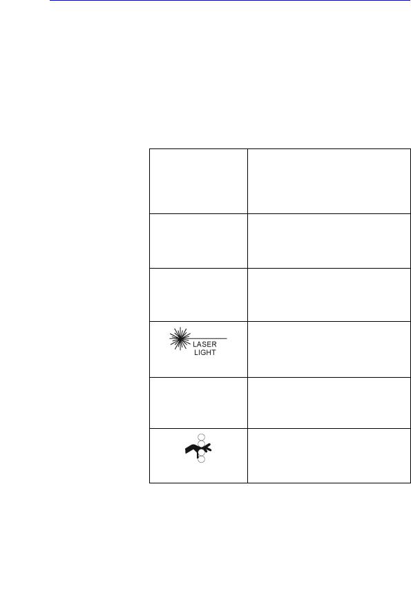
Standard hazard icons
Important information will always be preceded by either the exclamation point (!) contained within a triangle, or the symbols for “Danger”, “Warning” or “Caution”, as seen throughout this chapter. In addition to text, several different graphical icons (symbols) may be used to make you aware of specific types of hazards that could possibly cause harm. Even if a symbol isn’t used in this manual, it may be included for your reference.
Table 1-3: Standard hazard icons
ELECTRICAL
MECHANICAL
RADIATION
LASER
HEAT
PINCH
NOTE: |
Even if a symbol isn’t used on the product or in this manual, it |
|
may be included for your reference. |
1-8 |
Venue 50 – Basic Service Manual |
|
5447566-100 English Rev. 7 |
Loading...