


FCC Information
This device complies with Part 15 of the FCC Rules. EN Operation is subject to the following two
conditions: (1) This device may not cause harmful interference, and (2) this device must accept any interference received, including interference that may cause undesired operation.
In accordance with FCC requirements, changes or modifications not expressly approved by Thomson Inc. could void the user’s authority to operate this product.
This device generates and uses radio frequency (RF) energy, and if not installed and used properly, this equipment may cause interference to radio and television reception.
If this equipment does cause interference to radio or television reception (which you can determine by turning the equipment off and on), try to correct the interference by one or more of the following measures:
•Reorient the receiving antenna (that is, the antenna for the radio or television that is "receiving" the interference).
•Move the unit away from the equipment that is receiving interference.
For Your Safety
The AC power plug is polarized (one blade is wider than the other) and only fits into AC
power outlets one way. If the plug will not go into the outlet
completely, turn the plug over
and try to insert it the other way. If it still will not fit, contact a qualified electrician to change the outlet, or use a different one.
Do not attempt to bypass this safety feature.
CAUTION: TO PREVENT ELECTRIC SHOCK, MATCH WIDE BLADE OF PLUG TO WIDE SLOT, FULLY INSERT.
Technical Specification
Product: Spacemaker
Brand: GE
Model: 7-5295
Electrical Consumption
Power Supply: 120V~60Hz
Power Consumption: 72 Watts
• Plug the unit into a different wall outlet so that |
IMPORTER |
|
|
||||||
the unit and the equipment receiving interference |
Comercializadora Thomson de México, S.A. de C.V. |
||||||||
are on different branch circuits. |
Miguel de Cervantes Saavedra 57 |
|
|
||||||
If these measures do not eliminate the |
Col. Ampliación Granada |
|
|
||||||
C.P. 11529 Mexico D.F. |
|
|
|||||||
interference, please consult your dealer or an |
|
|
|||||||
Telefono: (55)25 81 53 20 |
|
|
|||||||
experienced radio/television technician for |
|
|
|||||||
RFC: CTM-980723-KS5 |
|
|
|||||||
additional suggestions. |
|
|
|||||||
|
|
|
|
|
|
|
|
||
Also, the Federal Communications Commission has |
|
|
|
|
|
|
|
|
|
prepared a helpful booklet, "How To Identify and |
|
|
|
|
|
|
|
|
|
Resolve Radio TV Interference Problems." This |
|
|
|
|
|
|
|
|
|
booklet is available from the U.S. Government |
|
|
|
|
|
|
|
|
|
Printing Office, Washington, DC 20402. Please |
|
|
|
|
|
|
|
|
|
specify stock number 004-000-00345-4 when |
|
|
|
|
|
|
|
|
|
ordering copies. |
|
|
|
|
|
CAUTION |
|
|
|
|
|
|
|
|
|
RISK OF ELECTRIC SHOCK |
|
|
|
|
|
|
|
|
|
DO NOT OPEN |
|
|
|
|
T H E L I G H T N I N G |
CAUTION: TO REDUCE THE |
THE EXCLAMATION |
||||||
|
FLASH AND ARROW- |
RISK OF ELECTRIC SHOCK, |
POINT WITHIN THE |
||||||
|
HEAD |
WITHIN THE |
D O N O T R E M O V E C O V E R |
T R I A N G L E |
I S A |
||||
|
T R I A N G L E |
I S |
A |
( O R B A C K ) . N O U S E R - |
WARNING |
SIGN |
|||
|
W A R N I N G |
S I G N |
S E RV I C E A B L E PA R T S I N - |
ALERTING YOU OF |
|||||
|
ALERTING YOU |
OF |
S I D E . R E F E R S E RV I C I N G |
I M P O R T A N T |
|||||
|
" D A N G E R O U S |
T O Q U A L I F I E D S E R V I C E |
I N S T R U C T I O N S |
||||||
|
VOLTAGE" |
INSIDE |
PERSONNEL. |
A C C O M PA N Y I N G |
|||||
|
THE PRODUCT. |
|
|
|
|
T H E P R O D U C T. |
|||
|
|
|
|
|
|
|
|||
|
|
SEE MARKING ON BOTTOM / BACK OF PRODUCT |
|
||||||
WARNING:TO PREVENT FIRE OR ELECTRICAL
SHOCK HAZARD, DO NOT EXPOSETHIS PRODUCT
TO RAIN OR MOISTURE.
Untitled-1 |
1 |
2/7/03, 10:08 AM |

FCC Information
Service Information |
For Your Records |
EN |
|
This product should be serviced only by those |
In the event that service should be required, |
||
|
|||
specially trained in appropriate servicing |
you may need both the model number and the |
|
|
techniques. For instructions on how to obtain |
serial number. In the space below, record the |
|
|
service, refer to the warranty at the end of the |
date and place of purchase, and the serial |
|
|
User’s Manuel. |
number: |
|
|
|
Model No.: |
|
|
|
Date of Purchase: |
|
|
|
Place of Purchase: |
|
|
|
Serial No.: |
|
Table of Content
FCC Information |
|
First Things First .......................... |
1 |
Tools Required ................................... |
1 |
Parts Packed with Your Unit ............ |
1 |
Before Mounting ............................... |
1 |
Mounting Procedure ......................... |
2 |
Before Plug-In .............................. |
4 |
Automatic Time Set ........................... |
4 |
Daylight Saving Time (DST) .............. |
4 |
U.S. Time Zone (Figure 1) ................. |
4 |
Canadian Time Zone (Figure 2) ........ |
5 |
Battery Backup Operation .......... |
5 |
Installing Backup Battery .................. |
5 |
General Controls ......................... |
6 |
Main Unit ........................................... |
6 |
Side Views .......................................... |
6 |
In Battery Compartment ................... |
6 |
The Remote Control .......................... |
7 |
Display .......................................... |
7 |
Using the Countertop |
|
Light ............................................. |
8 |
Replacing the Bulb ............................ |
8 |
Setting Clock ............................... |
8 |
Setting the Time ................................ |
8 |
Setting the Countdown Timer |
......... 8 |
Using the Radio ........................... |
9 |
Turning On the Radio ....................... |
9 |
Turning Off the Radio ....................... |
9 |
Adjusting Volume .............................. |
9 |
Selecting Radio Band ........................ |
9 |
Tuning to a Station ........................... |
9 |
Automatic Station Search ................. |
9 |
Radio Frequency Memory ................. |
9 |
Memory Recall ................................... |
9 |
Using the CD Player .................. |
10 |
Selecting CD Player ......................... |
10 |
Loading CD Disc ............................... |
10 |
Play and Pause Playback ................. |
10 |
Skip and Search Tracks .................... |
10 |
End Playback .................................... |
10 |
Repeat and Random Playback ........ |
10 |
Bass Sound ....................................... |
10 |
Care and Maintenance .............. |
11 |
Troubleshooting Tips for the |
|
Remote Control ............................... |
11 |
Precaution ........................................ |
11 |
U.S. Warranty ............................. |
12 |
Canadian Warranty ................... |
14 |
Untitled-1 |
2 |
2/7/03, 10:08 AM |
First Things First
EN Under Cabinet Mounting
Instructions
Tools Required
•Drill and 1/4" Drill Bit
•Ruler or Tape Measure
•Nail or Awl
•Scissors
•Screwdriver - Phillips
•Countersink (Optional)
•Masking Tape
•Safety Glasses
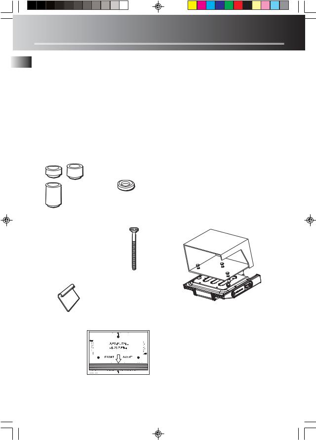
Parts Packed with your Unit
Spacers
3 — 1/4"
3 — 1/2" 3 — Washers
3 — 1"
USE:
3 — 2 3/4" Phillips head screws or
3 — 1 5/8" Phillips head screws
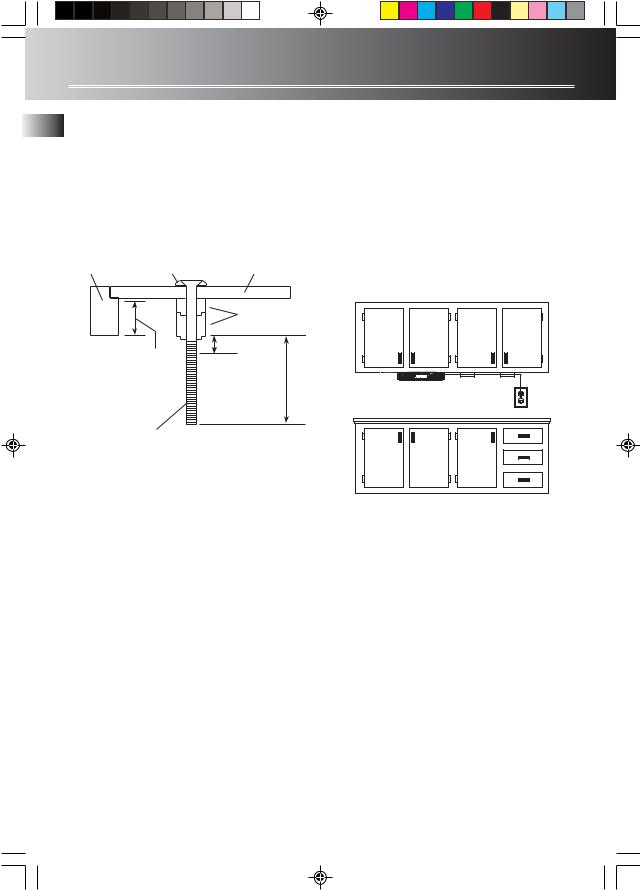
Before Mounting
Empty contents of the selected cabinet under which the unit will be mounted and thoroughly clean the underside of the cabinet to remove any grease residue which might be present. We recommend the unit be mounted at the front edge of the cabinet.
Important: For secure mounting, the screws must go into the radio to a depth of at least 3/8". If the overall length from the bottom of the cabinet shelf to the bottom of the overhang is more than 1 3/4", then a wood shim will be necessary. A shim can be made from a sheet of plywood, using the Template to locate the central lines for drilling the 1/4" mounting holes. The shim can be located between the cabinet shelf bottom and spacers. Make sure the wood is at least as thick as the excess over 1 3/4" If a shim is necessary, longer screws are required. Longer screws (Type #10-32) are available at most local hardware stores.
Cut out the Template on the line indicated. The Template size and screw hole positions are identical to the top of the clock radio.
2 — Cord hooks
1 — Mounting
template
1
Untitled-1 |
3 |
2/7/03, 10:08 AM |

First Things First
Mounting Procedure
1.If your cabinet does not have an overhang:
(a)Position Template in desired location on underside of cabinet, flush with front edge.
(b)Then tape Template in place, and go to Step 2 (Read “Caution”).
FRONT EDGE |
MOUNTING |
OF CABINET |
TEMPLATE |
If your cabinet has an overhang:
(a)Measure the thickness of the overhang.
(b)Fold front of Template downward along the printed guideline that is closest to the thickness of your cabinet.
(c)Tape fold-down portion to backside of overhang, Tape Template to cabinet underside.
MEASURE THICKNESS OF
CABINET OVERHANG
 EN
EN
FOLD TEMPLATE ON
DOTTED LINE
NOTE: If your cabinet has glue blocks or other obstructions, cut out corresponding areas on the Template to clear them. Do not cut out or cut through the screw holes indicated on the Template.
CAUTION: It is recommended that safety glasses be worn while drilling screw holes to prevent the possibility of eye injury.
2.Drill 1/4 -inch diameter holes through the underside of the cabinet bottom shelf using the three points marked on the Template.
Helpful Hints:
On wooden cabinets you may want to mark and start the drill holes with a nail or an awl. Be sure to hold the drill very firmly against the cabinet to reduce “walking” of the drill bit from the markings.
Use masking tape above the hole locations on inside of wooden cabinet shelf to help reduce splintering.
If installing the unit under a wood cabinet, you may wish to countersink the drilled hole from the INSIDE of the cabinet if a countersink attachment for your drill is available. This will eliminate the use of washers and allow the screw heads to be flush with the floor of your cabinet. If you cannot countersink the holes, use the supplied washers.
2
Untitled-1 |
4 |
2/7/03, 10:08 AM |
First Things First
EN 3. |
Remove Template and clean drill shavings from |
|
inside and underside of cabinet. |
4. |
If your cabinet does not have an |
|
overhang, go to Step 5. |
|
If your cabinet has an overhang, select the |
|
spacer or combination of spacers that is equal |
|
to or longer than the cabinet overhang. |
CABINET |
WASHER |
CABINET |
OVERHANG |
BOTTOM |
|
|
|
SPACERS |
|
|
3/ " MINIMUM |
|
|
8 |
EQUAL TO OR
LONGER THAN
CABINET 3/4" MAXIMUM
OVERHANG
8.Extend cord towards electrical outlet and secure by using the Cord Hooks to hold cord out of the way. For most attractive appearance, place Cord Hooks at back edge of cabinet (on or next to wall) directly over outlet to be used. To attach Cord Hooks, peel off adhesive back and attach to a clean, dry surface on underside of cabinet or back wall. Plug Cord into 120-volt AC electrical outlet.
We recommend that the line cord be fully extended for best FM reception.
SELECTED SCREWS WHICH MEET MINIMUM, BUT DO NOT EXCEED MAXIMUM LENGHT.
5.Insert screws FROM INSIDE THE CABINET. The washers must be used on metal cabinets, and on wood cabinets if you did not countersink the drilled holes. Position washers, flat side down, and place screws into the holes.
If your cabinet does not have an overhang, go to Step 7.
6.Hold screw heads down while you push the selected spacers onto the screws under the cabinet. Be sure to push up spacers until they are firmly against the cabinet bottom and/or fully nested (if more than one is used).
7.Align radio under the screws. Hold the screw holes in the top of the clock radio against the mounting screws and partially tighten the screws.
Do not fully tighten until all 3 screws have been started. (The top front edge of the clock radio should clear the overhang.)
3
Untitled-1 |
5 |
2/7/03, 10:08 AM |
 Loading...