


JDP39DN1BB
GE JDP39DN1BB, JDP39DN1CC, JDP39DN1WW, JDP39DN2BB, JDP39DN2CC Installation Guide
...
nstructlons Drop-In Range
1Ilnstallation 1Electric
JDS28, JDP39
[-_ Questions? Call 800.GE.CARES (800.432.2737) or Visit our Website at: ge.com I
BEFORE YOU BEGIN • Proper installation is the responsibility of the
Read these instructions carefully and
completely.
• iMPORTANT - Savethese
instructions for local inspector's use.
• iMPORTANT - Observeall
governing codes and ordinances.
• Note to Installer - Be sure to leave these
instructions with the consumer.
• Note to Consumer - Keep these instructions
for future reference.
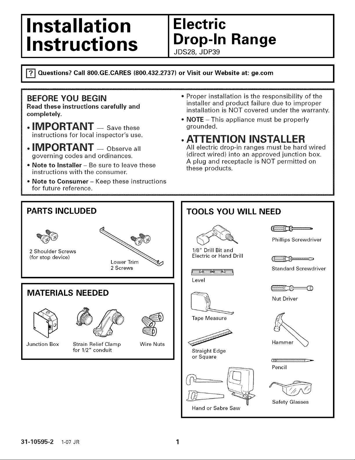
PARTS INCLUDED
%%
2 Shoulder Screws
(for stop device)
2 Screws
installer and product failure due to improper
installation is NOT covered under the warranty.
NOTE - This appliance must be properly
grounded.
ATTENTION iNSTALLER
All electric drop-in ranges must be hard wired
(direct wired) into an approved junction box.
A plug and receptacle is NOT permitted on
these products.
TOOLS YOU WILL NEED
Phillips Screwdriver
1/8" Drill Bit and
Electric or Hand Drill
Standard Screwdriver
MATERIALS NEEDED
Junction Box
31-10595-2 1-07 JR 1
Strain Relief Clamp
for 1/2" conduit
Wire Nuts
Level
Tape Measure
Straight Edge
or Square
Hand or Sabre Saw
Nut Driver
Hammer
C_i I C:_ "
Pencil
Safety Glasses
Installation Instructions
IMPORTANT SAFETY INSTRUCTIONS
FOR YOUR SAFETY
-4,WARNING: Forpersonalsafety,
remove house fuse or open circuit breaker
before beginning installation. Failure to do
so could result in serious injury or death.
• All rough-in and spacing dimensions must be
met for safe use of your range.
• To reduce the risk of burns or fire when
reaching over hot surface elements, cabinet
storage space above the cooktop should be
avoided. If cabinet storage space is to be
provided above the cooktop, the risk can
be reduced by installing a range hood that
protrudes at least 5" beyond the front of
the cabinets. Cabinets installed above the
cooktop must be no deeper than 13".
• Be sure your appliance is properly installed
and grounded by a qualified technician.
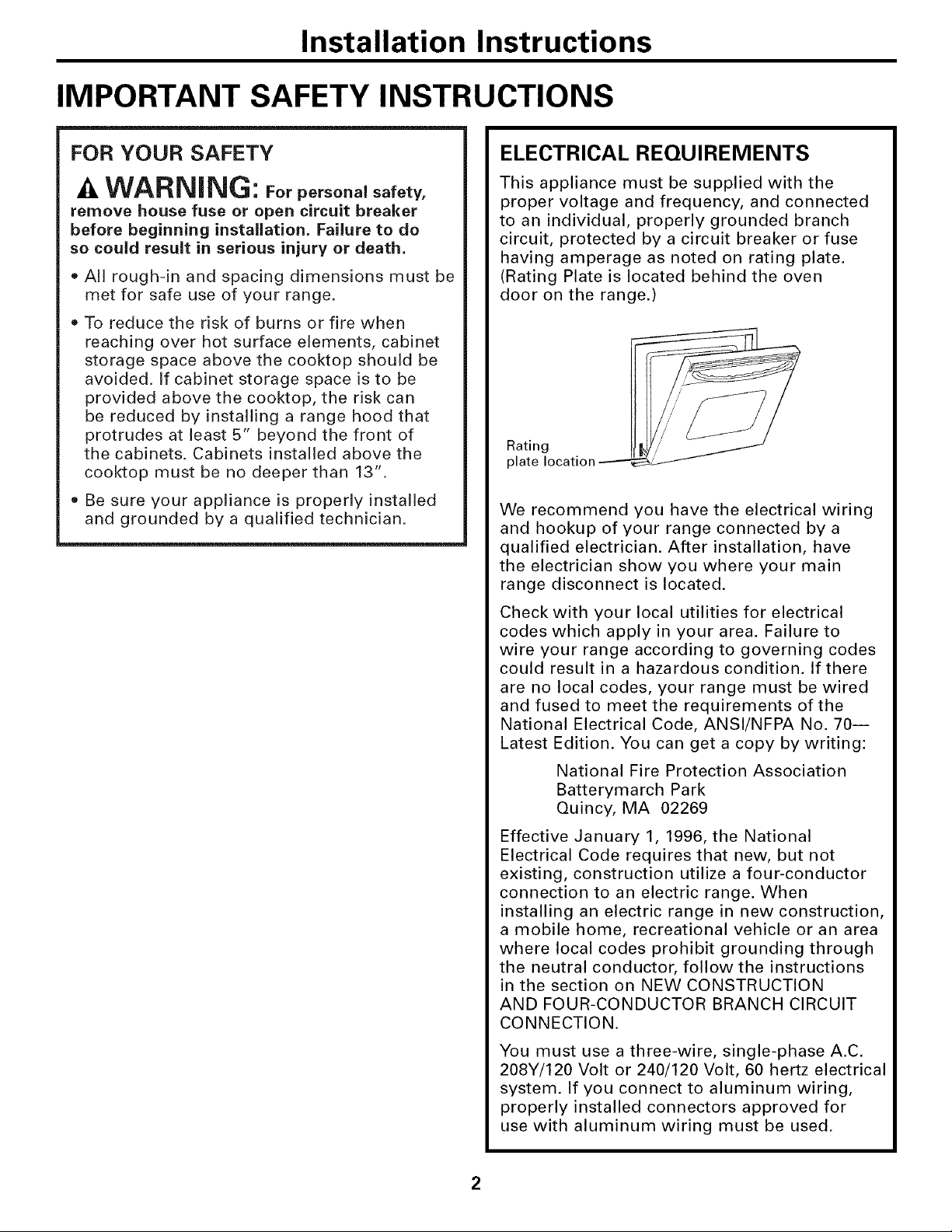
ELECTRICAL REQUIREMENTS
This appliance must be supplied with the
proper voltage and frequency, and connected
to an individual, properly grounded branch
circuit, protected by a circuit breaker or fuse
having amperage as noted on rating plate.
(Rating Plate is located behind the oven
door on the range.)
We recommend you have the electrical wiring
and hookup of your range connected by a
qualified electrician. After installation, have
the electrician show you where your main
range disconnect is located.
Check with your local utilities for electrical
codes which apply in your area. Failure to
wire your range according to governing codes
could result in a hazardous condition. If there
are no local codes, your range must be wired
and fused to meet the requirements of the
National Electrical Code, ANSl/NFPA No. 70i
Latest Edition. You can get a copy by writing:
National Fire Protection Association
Batterymarch Park
Quincy, MA 02269
Effective January 1, 1996, the National
Electrical Code requires that new, but not
existing, construction utilize a four-conductor
connection to an electric range. When
installing an electric range in new construction,
a mobile home, recreational vehicle or an area
where local codes prohibit grounding through
the neutral conductor, follow the instructions
in the section on NEW CONSTRUCTION
AND FOUR-CONDUCTOR BRANCH CIRCUIT
CONNECTION.
You must use a three-wire, single-phase A.C.
208Y/120 Volt or 240/120 Volt, 60 hertz electrical
system. If you connect to aluminum wiring,
properly installed connectors approved for
use with aluminum wiring must be used.
Installation Instructions
PRE-INSTALLATION CHECKLIST
• Move Range Indoors In Front of Cabinet
Opening
• Protect the kitchen floor! Flatten and place
a piece of the shipping carton in front of the •
installation location to protect the flooring. •
• Inspect Installation Location
Inspect cutout dimensions and location
of electrical junction box to be sure it fits
within the layout location. See page 4.
Refer to alternate construction section for
the following non-standard installations.
a. Counter opening extends to the wall:
Maintop Filler Kit (JXS66XX), or
Backguard Kit (JXS32XX).
WARNING: If you do not use these kits,
the anti-tip bracket must fit under an
attachment to the wall that can withstand •
a force of 200 Ibs. in the upward direction.
See Step 1 under INSTALL THE RANGE.
b. Island Installation:
To provide an optimum installation, the
top surface of the countertop must be
level and flat (lie on the same plane) •
around the 3 sides that are adjacent to
range cooktop. Proper adjustments to
make the top flat should be made or
gaps between the countertop and range
cooktop may occur. Forcing the cooktop
to fit may cause excessive gaps.
To obtain Kits:
a. Visit GE Web Site (See page 1)
b. Call GE Answer Center (See page 1)
c. Contact Dealer
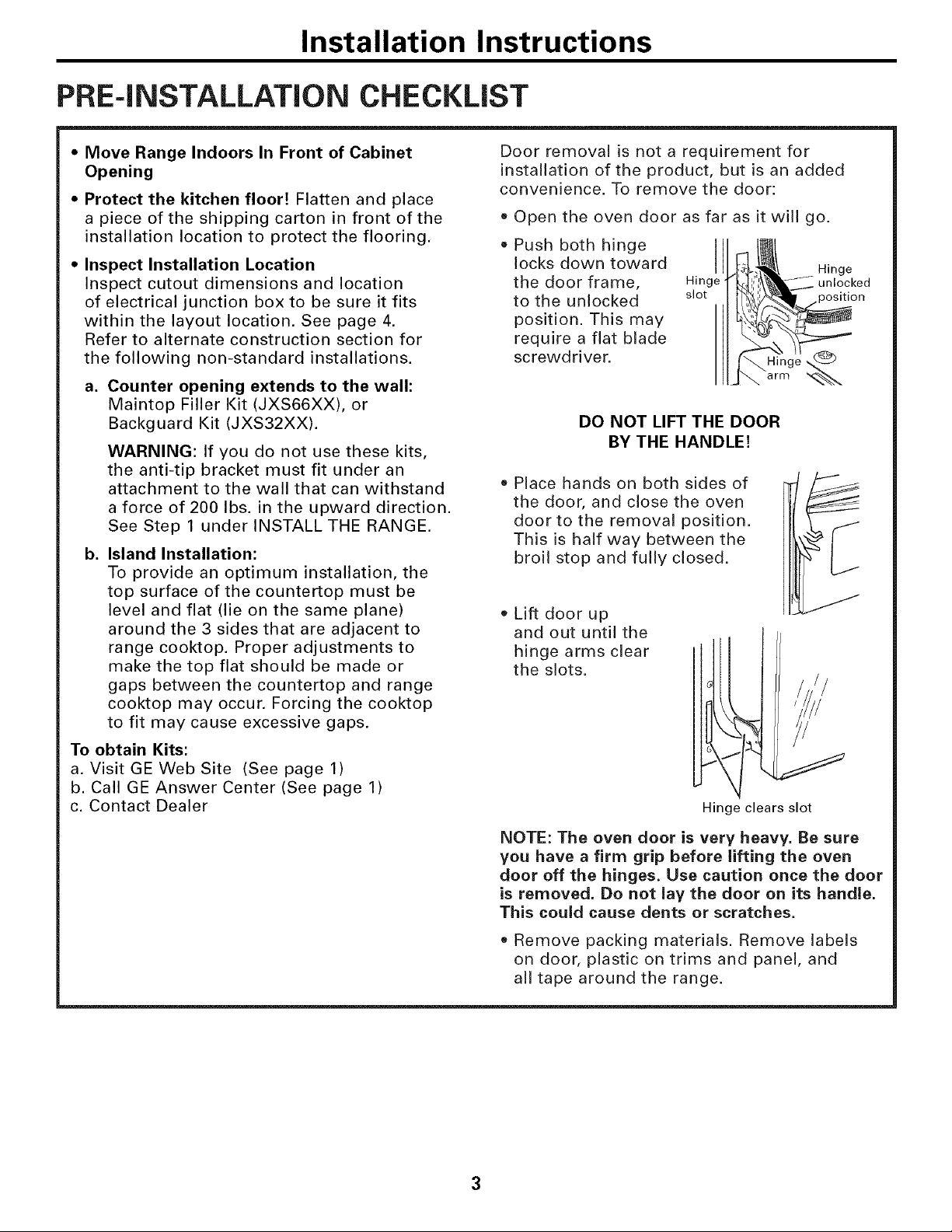
Door removal is not a requirement for
installation of the product, but is an added
convenience. To remove the door:
Open the oven door as far as it will go.
Push both hinge
locks down toward
the door frame,
to the unlocked
position. This may
require a flat blade
screwdriver.
DO NOT LIFT THE DOOR
BY THE HANDLE!
Place hands on both sides of
the door, and close the oven
door to the removal position.
This is half way between the
broil stop and fully closed.
Lift door up
and out until the
hinge arms clear
the slots.
I
Hinge
slot
_Hinge
Hinge clears slot
arm
Hinge
unlocked
NOTE: The oven door is very heavy. Be sure
you have a firm grip before lifting the oven
door off the hinges. Use caution once the door
is removed. Do not lay the door on its handle.
This could cause dents or scratches.
• Remove packing materials. Remove labels
on door, plastic on trims and panel, and
all tape around the range.
Installation Instructions
PRE-INSTALLATION CUTOUT AND
REQUIRED CLEARANCES
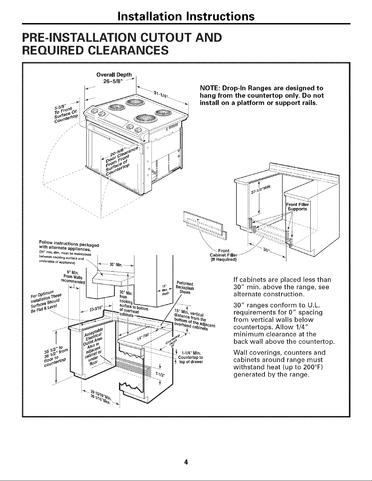
Overall Depth
26=5/8"
NOTE: Drop-In Ranges are designed to
hang from the countertop only. Do not
install on a platform or support rails.
Follow instructions packaged
with alternate appliances.
(24" rain. dim. must be maintained
between COOking surface and
underside of appliance)
Preformed
13" Backspbsh
Shown
35 ! r 1=1/4"Min.
36 1 Countertop to
coU
3O
top of drawer
_ Front _ _ 3(_,_
Cabinet Fil|er _
(if Required)
If cabinets are placed less than
30" min. above the range, see
alternate construction.
30" ranges conform to U.L.
requirements for 0" spacing
rnthe
from vertical walls below
countertops. Allow 1/4"
minimum clearance at the
back wall above the countertop.
Wall coverings, counters and
cabinets around range must
withstand heat (up to 200°F)
generated by the range.
4
Installation Instructions
PREPARE TO INSTALL THE RANGE
STANDARD INSTALLATION
Wall
1/4" rain.
flat
t],
23-3/16"
9/16" rain.
flat _1
I
....... i=
_'_ 29-15/16"-30-1/16"
smooth cut
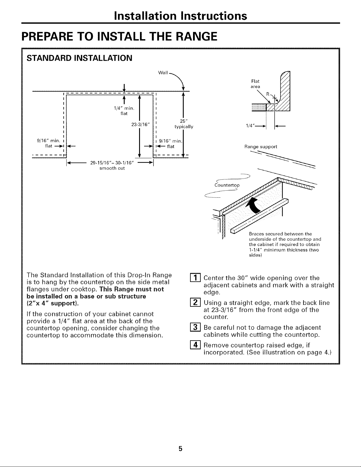
The Standard Installation of this Drop-In Range
is to hang by the countertop on the side metal
flanges under cooktop. This Range must not
be installed on a base or sub structure
(2"x 4" support}.
If the construction of your cabinet cannot
provide a 1/4" flat area at the back of the
countertop opening, consider changing the
countertop to accommodate this dimension.
9/16" rain.
T
25"
typically
Countertop
iT] Center the 30" wide opening over the
adjacent cabinets and mark with a straight
edge.
[_ Using a straight edge, mark the back line
at 23-3/16" from the front edge of the
counter.
E_ Be careful not to damage the adjacent
cabinets while cutting the countertop.
[] Remove countertop raised edge, if
incorporated. (See illustration on page 4.)
1/
Range support
Braces secured between the
underside of the countertop and
the cabinet if required to obtain
1-1/4" minimum thickness (two
sides)
 Loading...