


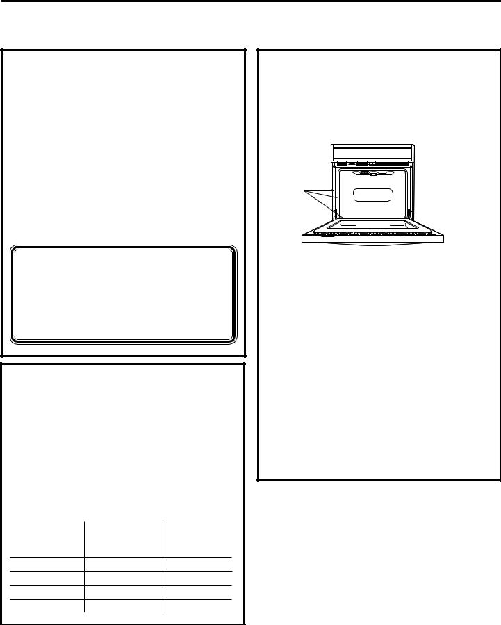
GE JCTP70, JCTP30, JCKS10, JCKP70, JCKP30 User Manual
...Installation
Instructions
Built-In Wall Oven
27” (68.6 cm) models
JCKS10, JCKP30, JCKP70, PCK916, PCK920
30” (76.2 cm) models
JCTP30, JCTP70, PCT916, PCT920
If you have questions, call 1.800.561.3344 or visit our website at: www.geappliances.ca
Before You Begin |
• Proper installation is the responsibility |
|
of the installer and product failure due |
||
Read these instructions carefully and completely. |
to improper installation is NOT covered |
|
• IMPORTANT—Save these |
under warranty. |
|
• NOTE—This appliance must be properly |
||
instructions for local inspector’s use. |
||
grounded. |
||
• IMPORTANT—Observe all |
||
• ATTENTION INSTALLER |
||
governing codes and ordinances. |
||
• Note to Installer—Be sure to leave these |
All electric wall ovens must be hard wired |
|
instructions with the consumer. |
(direct wired) into an approved junction |
|
• Note to Consumer—Keep these |
box. A plug and receptacle is NOT permitted |
|
on these products. |
||
instructions for future reference. |
||
|
||
|
|
Parts Included
(Appearance will vary.)
Screws for Installation (8-18 x .750 flat head Phillips wood screws)
WB07T10578 – Black WB07T10579 – SS Optional 68.6 cm (27″) Metal Bottom Trim Assembly (on some models or can be purchased separately)
68.6 cm (27″) Metal Bottom Trim
76.2 cm (30″) Metal Bottom Trim Assembly
Materials Needed
Wire Nuts
Strain Relief Clamp |
Junction |
for 1/2” conduit |
Box |
91 cm (36”) of String
Tools Needed
1/8” (3 mm) Drill Bit and |
Phillips |
Electric or Hand Drill |
Screwdriver |
31-10666-3 |
11-07 JR |
1
Installation Instructions
IMPORTANT SAFETY INSTRUCTIONS
For Your Safety
•Be sure your oven is installed properly by a qualified installer or service technician.
•Be sure the oven is securely installed in a cabinet that is firmly attached to the house structure. Weight on the oven door could cause the oven to tip and result in injury. Never allow anyone to climb, sit, stand or hang on the oven door.
•Make sure the cabinets and wall coverings
around the oven can withstand the temperatures (up to 93°C [200°F]) generated by the oven.
 WARNING: The electrical
 power to the oven supply line must be shut off while line connections are being made. Failure to do so could result in serious injury
or death.
Electrical
Requirements
This appliance must be supplied with the proper voltage and frequency, and connected to an individual, properly grounded branch circuit, protected by a circuit breaker or fuse. See the rating plate located on the oven frame to determine the rating of the product. Use the chart below to determine the minimum recommended dedicated circuit protection.
|
|
|
Recommended |
|
KW Rating |
KW Rating |
Circuit Size |
|
240V |
208V |
(Dedicated) |
|
≤4.8 KW |
≤4.1 KW |
20 Amp |
4.9 |
KW–7.2 KW |
4.3 KW–6.2 KW |
30 Amp |
7.3 |
KW–9.6 KW |
6.3 KW–8.3 KW |
40 Amp |
9.7 |
KW–12.0 KW |
8.4 KW–10.4 KW |
50 Amp |
Electrical
Requirements (cont.)
Rating Plate is located on oven side trim, side front frame or lower front frame.
Rating Plate |
Location |
We recommend you have the electrical wiring and hookup of your oven connected by a qualified electrician. After installation, have the electrician show you where your main oven disconnect is located.
Check with your local utilities for electrical codes which apply in your area. Failure to wire your oven according to governing codes could result in a hazardous condition. If there are no local codes, your oven must be wired and fused to meet the requirements of CAN/
CSA C22.2 No. O-M91 or latest edition.
You must use a three-wire, single-phase A.C.
208Y/120 Volt or 240/120 Volt, 60 hertz electrical system. If you connect to aluminum wiring, properly installed connectors approved for use with aluminum wiring must be used.
2
Installation Instructions

 Pre-Installation Checklist
Remove packaging materials. Check behind hinges and under false bottom.
Remove labels on the outside of the door, plastic on trims and panel, all tape around the oven and any shipping screws securing the oven to the
base pad.
Oven Racks
EASY |
|
|
|
|
I |
|
|
|
|
NSTALL |
|
|
|
|
EASY INSTALLATIONTOF YOUR NEW |
||||
30" |
ION |
|
|
|
OVENOF |
YOUR |
|
||
30" WALLWALL O |
|
NEW |
||
|
|
VEN |
||
Literature
Pack
Open oven door and remove literature pack and oven racks.
Remove Installation Instructions from literature pack and read them carefully before you begin.
Be sure to place all literature, Owner’s Manual, Installations, etc. in a safe place for future reference.
Door removal is not a requirement for installation of the product, but is an added convenience. To remove the door:
Open the oven door as far as it will go.
Push both hinge locks down toward the door frame,
to the unlocked position. This may require a flat blade screwdriver.
Hinge 
HingeSlot
Slot
Hinge
Unlocked
Position
Hinge
ArmArm
DO NOT LIFT THE DOOR
BY THE HANDLE!
Place hands on both sides of the door, and close the oven door to the removal position, which is most of the way closed.
Lift door up and out until the hinge arms clear the slots.
Hinge Clears Slot
NOTE: The oven door is very heavy.
Be sure you have a firm grip before lifting the oven door off the hinges. Use caution once the door is removed. Do not lay the door on its handle. This could cause dents or scratches.
Place the oven on a table or platform even with the cutout opening. (Platform must support 68 Kg [150 lbs.].)
Remove the bottom trim from the top
of the oven. It will be installed at the end of the installation process. The trim is wrapped separately and taped to the top of the unit
3
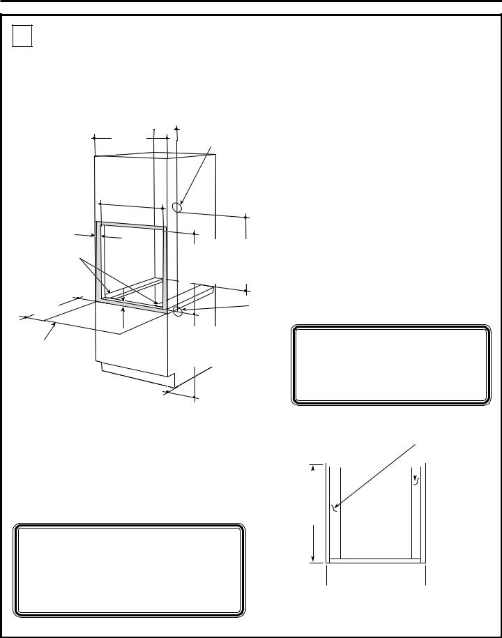
Installation Instructions
A Cutout for 27″ (68.6 cm) Single Built-In
Ovens only
For JCKP30, JCKP70, JCKS10, PCK916, PCK920 models only.
|
12.7 cm |
|
|
|
(5”) Max. |
|
|
|
from the left |
|
|
Cabinet |
or |
right |
|
Width |
|
side |
Junction Box |
68.6 cm |
|
|
|
|
|
Location |
|
(27”) |
|
|
|
|
|
|
|
Cutout Width |
|
||
63.5 cm |
|
|
|
(25”) Min. |
|
||
Cabinet Width |
68.6 cm (27”) |
Recommended |
|
Cutout Location |
|
from Floor |
82.6 cm (32 1/2”) |
Cutout Depth |
59.7 cm |
|
(23 1/2”) Min. |
|
|
|
|
64.1 cm |
|
|
|
|
|
|
|
|
|
|
Cutout Width |
63.5 cm |
||||||||
Allow 2.5 cm (1”) |
(25 1/4”) Max. |
|
|
|
|
|
|
|
|
|
|
|
|
|
|
|
(25”) Min. |
|||||||
|
|
|
|
|
|
|
|
|
|
|
|
|
|
|
|
|
|
|
||||||
for overlap of oven |
|
|
|
|
|
|
|
|
|
|
|
|
|
|
|
|
|
|
|
64.1 cm |
||||
over side edges of |
|
|
|
|
|
|
|
|
|
|
|
|
|
|
|
|
|
|
|
|||||
cutout |
|
|
|
|
|
|
|
|
|
Cutout |
|
55.9 cm (22”) Min. |
|
|
|
|
|
(25 1/4”) Max. |
||||||
|
|
|
|
|
|
|
|
|
|
|
|
|
|
|
|
|
|
|||||||
5 cm x 10 cm |
|
|
|
|
|
|
|
|
|
|
above base rail |
|
|
|
|
|
|
|
|
|||||
|
|
|
|
|
|
|
|
|
Height |
|
|
|
|
|
|
|
|
|
|
|
|
|||
(2” x 4”) |
|
|
|
|
|
|
|
|
|
|
|
|
Cutout Height |
70.2 cm |
||||||||||
|
|
|
|
|
|
|
|
|
70.2 cm |
(27 5/8”) Min. |
|
|||||||||||||
or equivalent |
|
|
|
|
|
|
|
|
|
|
||||||||||||||
runners level |
|
|
|
|
|
|
|
|
|
71.4 cm |
(28 1/8”) Max. |
|
|
|
|
|
|
(27 5/8”) Min. |
||||||
|
|
|
|
|
|
|
|
|
|
|
|
|
|
|
|
|
|
|
||||||
with bottom |
|
|
|
|
|
|
|
|
|
|
|
|
|
|
|
|
|
|
|
71.4 cm |
||||
of cutout |
|
|
|
|
|
|
|
|
|
|
|
|
|
|
|
|
|
|
|
|||||
|
50.8 cm |
|
|
|
|
|
|
|
|
|
|
|
|
|
|
Alternate |
|
|
|
|
|
(28 1/8”) Max. |
||
|
|
|
|
|
|
|
|
|
|
|
|
|
|
|
|
|
|
|
|
|
|
|
||
|
(20”) |
|
|
|
|
|
|
|
|
|
|
|
|
|
|
Junction Box |
|
|
|
|||||
|
|
|
|
|
|
|
|
|
|
|
|
|
|
|
|
Location – |
|
|
|
|
|
|
|
|
|
|
|
|
|
|
|
|
|
|
|
|
Recommended |
|
access from |
|
|
|
|
|
|
|
|
||
|
|
|
|
Allow |
2.5 cm |
|
|
|
|
|
|
|
|
|
|
|
||||||||
|
|
|
|
|
|
|
adjacent |
NOTE: If the cabinet does not |
||||||||||||||||
|
|
|
|
|
|
|
|
|
|
|
|
cutout location |
|
cabinet may |
||||||||||
Allow a minimum |
|
(1”) minimum |
|
|
|
|
|
|||||||||||||||||
|
for overlap of |
|
|
|
|
from floor 82.6 cm |
be required |
have a front frame and the sides |
||||||||||||||||
|
|
|
|
|
||||||||||||||||||||
of 50.8 cm (20”) for |
|
oven top and |
|
|
(32 1/2”) |
|
||||||||||||||||||
clearance to adjacent |
|
|
|
of cutout |
|
|
|
|
|
|
|
|
are less than 1.9 cm (3/4”) thick, |
|||||||||||
|
bottom |
|
|
|
|
|
|
|
||||||||||||||||
corners, drawers, walls, |
|
|
|
|
|
|
|
|||||||||||||||||
|
|
|
|
|
|
|
|
|
|
|
|
|
|
|||||||||||
etc. when door is open |
|
|
|
|
|
|
|
|
|
|
|
|
|
|
shim both sides equally to |
|||||||||
|
|
|
|
|
|
|
|
|
|
|
|
|
|
|||||||||||
|
|
|
|
|
|
|
|
|
|
|
|
|
|
|
|
|
establish the cutout width. |
|||||||
|
|
|
|
|
|
|
|
|
|
|
|
|
|
|
|
|
|
|
|
|
|
5 cm 2"x 10x 4"cmor(2” x 4”) or |
||
|
|
|
|
|
|
|
|
|
|
|
|
|
|
|
|
|
|
|
|
|
|
equivalent ru ners level |
||
|
|
|
|
|
|
|
|
|
|
|
|
|
|
|
|
|
|
|
|
|
|
Equivalent |
||
|
|
|
|
|
|
|
|
|
|
|
|
|
|
|
|
|
|
|
|
|
|
with bottom of cutout |
||
If the cabinet does not have a solid bottom, |
|
|
|
|
|
|
Runners |
|||||||||||||||||
two braces or runners must be installed |
|
|
|
|
|
|
|
|
|
|||||||||||||||
level with the bottom of the cutout to |
|
|
|
|
|
|
|
|
|
|||||||||||||||
|
|
|
|
|
|
|
|
|
||||||||||||||||
|
|
|
|
|
|
|
|
|
||||||||||||||||
support the weight of the oven. For single |
|
|
|
|
|
|
|
|
|
|||||||||||||||
|
|
|
|
|
|
|
|
|
||||||||||||||||
ovens, the runners and braces must |
|
|
|
|
|
|
|
|
|
|||||||||||||||
support 68 kg (150 lbs.). |
|
|
|
|
|
|
|
61 |
|
cm |
|
|
|
|
|
|||||||||
|
|
|
|
|
|
|
|
|
|
|
|
|
|
|
|
|
|
|
|
|
|
|||
|
|
|
|
|
|
|
|
|
|
|
|
|
|
|
|
|
24" |
|
|
|
|
|
||
|
|
|
|
|
|
|
|
|
|
|
|
|
|
|
|
|
(24”) |
|
|
|
|
|||
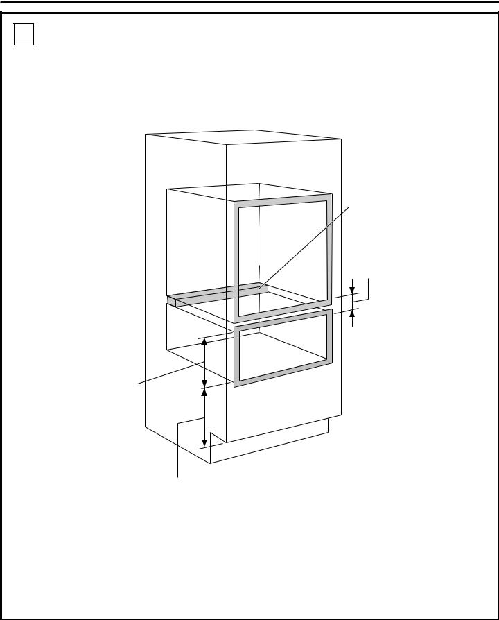
NOTE: If marks, blemishes or the cutout opening are visible above the installed oven, it may be necessary to add wood shims under the runners and front trim until the marks or opening are covered.
 45.718"cm (18”)

 68.627"cm (27”)
These ovens are not approved for stackable installation.
4

Installation Instructions
A Cutout for 30″ (76.2 cm) Single Built-In
Ovens only For JCTP30, JCTP70, PCT916, PCT920 models only.
|
|
|
|
Cutout Width |
|
|
24.1 cm |
|
|
|
Cabinet Width |
76.2 cm (30”) |
|||||||||
|
|
|
|
|
72.4 cm |
|
|
|
|
|
|||||||||||
|
|
|
|
|
|
|
(9 1/2”) |
|
|
|
Recommended |
|
|||||||||
|
|
|
|
(28 1/2”) Min. |
|
|
|
|
|
|
|||||||||||
|
|
|
|
|
|
Max. |
|
|
|
|
|||||||||||
|
|
|
|
|
72.7 cm |
|
|
|
|
|
|
||||||||||
|
|
|
|
|
|
|
|
|
|
|
|
|
Cutout Location |
|
|||||||
|
|
|
|
(28 5/8”) Max. |
|
|
|
|
|
|
|
|
|
|
|
||||||
|
|
|
|
|
|
|
|
|
|
|
|
|
|
|
|
|
|
|
|
from Floor |
82.6 cm (32 1/2”) |
|
|
|
|
|
|
|
|
|
|
|
|
|
|
|
|
|
|
|
|
||
|
Allow 1.75 cm |
|
|
|
|
|
|
|
|
|
|
|
|
|
|
|
Junction Box |
Cutout Depth |
59.7 cm |
||
|
|
|
|
|
|
|
|
|
|
|
|
|
|
|
|
|
(23 1/2”) Min. |
||||
|
(11/16”) |
|
|
|
|
|
|
|
|
|
|
|
|
|
|
|
Location |
|
|||
|
for overlap |
|
|
|
|
|
|
|
|
|
|
|
|
|
|
|
|
|
Cutout Width |
72.4 cm |
|
|
of oven over |
|
|
|
|
|
|
|
|
|
|
|
|
|
|
|
|
|
|||
|
side edges of |
|
|
|
|
|
|
|
|
|
|
|
|
|
|
|
|
|
|
(28 1/2”) Min. |
|
|
cutout |
|
|
|
|
|
|
|
|
|
|
|
|
|
|
|
|
|
|
||
|
|
|
|
Opening |
|
|
|
|
|
|
|
72.7 cm |
|||||||||
|
|
|
|
Cutout |
|
|
|
|
|||||||||||||
|
|
|
|
between |
|
Height |
|
|
|
|
|
|
(28 5/8”) Max. |
||||||||
|
|
|
|
55.9 cm (22”) |
|
|
|||||||||||||||
|
|
|
|
inside walls |
|
69.2 cm |
|
|
|
|
|||||||||||
|
|
|
|
must be at |
|
(27 1/4”) Min. |
|
|
to Bottom of |
|
Cutout Height |
69.2 cm |
|||||||||
|
|
|
|
least 72.4 |
cm |
|
|
69.4 cm |
|
|
Junction Box |
|
|||||||||
|
|
|
|
(28 1/2”) |
wide |
|
|
(27 5/16”) Max. |
|
|
|
|
|
|
(27 1/4”) Min. |
||||||
|
|
|
|
|
|
|
|
||||||||||||||
|
|
|
|
|
|
|
|
|
|
|
|
|
|
|
|
|
|
|
|
|
|
|
53.3 cm |
|
|
|
|
|
|
|
|
|
|
|
|
|
|
|
|
|
|
|
69.4 cm |
|
|
|
|
|
|
|
|
|
|
|
|
|
|
|
|
|
|
|
|
(27 5/16”) Max. |
|
|
(21”) |
|
|
|
|
|
|
|
|
|
|
|
|
|
|
|
|
|
|
|
|
|
|
|
|
|
|
|
|
|
|
|
|
|
|
|
|
|
|
|
|
NOTE: If the cabinet does not |
|
|
|
|
|
Allow 2.5 |
cm (1”) |
|
|
|
|
|
|
|
|
||||||||
|
|
|
|
|
|
Recommended |
|
|
|
||||||||||||
Allow a minimum |
|
for |
overlap of |
|
|
|
|
cutout location |
|
|
|
have a front frame and the sides |
|||||||||
|
oven |
top and |
|
|
|
|
from floor |
|
|
|
|||||||||||
of 53.3 cm (21”) |
|
3.2 cm (11⁄4”) |
|
|
|
|
82.6 cm (32 1/2”) |
|
are less than 1.9 cm (3/4”) thick, |
||||||||||||
for clearance to |
|
bottom of cutout |
|
|
|
|
|||||||||||||||
|
|
|
|
|
|
|
|
|
|||||||||||||
adjacent corners, |
|
|
|
|
|
|
|
|
|
|
|
|
|
|
|
|
|
shim both sides equally to |
|||
drawers, walls, etc. |
|
|
|
|
|
|
|
|
|
|
|
|
|
|
|
|
|
||||
when door is open |
|
|
Cabinet |
|
|
|
|
|
|
|
|
|
|
|
establish the cutout width. |
||||||
|
|
|
|
|
|
|
|
|
|
|
|
|
|||||||||
|
|
|
|
|
|
|
|
|
|
|
|
|
|
|
|
||||||
|
|
|
|
|
|
|
|
|
|
|
|
|
|
|
|
||||||
|
|
|
|
|
Width |
|
|
|
|
|
|
|
|
|
|
|
|||||
|
|
|
76.2 cm (30”) |
|
|
|
|
|
|
|
|
|
|
||||||||
|
|
C |
5 cm x 10 cm |
|
|
2" x 4" or |
|
|
|
L |
EQUIVALENT(2” x 4”) or |
|
|
|
RUNNERS |
|
|
|
equivalent |
If the cabinet does not have a solid bottom, |
|
|
runners level |
|
|
with bottom |
|
two braces or runners must be installed |
|
|
of cutout |
level with the bottom of the cutout to |
|
|
|
support the weight of the oven. For single |
|
|
|
ovens, the runners and braces must |
Suitable |
|
|
support 68 kg (150 lbs.). |
|
|
|
Bracing |
|
|
|
|
to Support |
|
|
|
SUITABLE |
|
|
|
Runners |
|
|
NOTE: If marks, blemishes or the |
BRACING |
|
|
TO SUPPORT |
21 5/8" |
|
|
RUNNERS |
OVER CENTERLINE |
|
|
|
|
54.9 cm |
|
cutout opening are visible above the |
|
(21 5/8”) |
|
|
OF CABINET |
|
|
installed oven, it may be necessary to |
|
Over Centerline |
|
|
of Cabinet |
|
|
add wood shims under the runners and |
|
|
|
front trim until the marks or opening |
These ovens are not approved |
||
are covered. |
for stackable installation. |
|
|
|
|
||
5

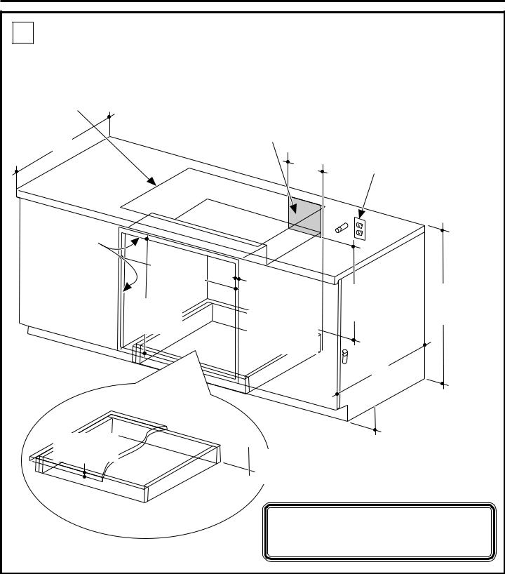
Installation Instructions
ACutout for 27″ (68.6 cm) Single Built-In Ovens only
Under Counter For JCKP30, JCKP70, JCKS10, PCK916, PCK920 models only.
Electric cooktops may be installed over this oven. See cooktop installation instructions for cutout size. See label on top of oven for approved cooktop models.
63.5 cm (25”)
Top and/or side fillers |
|
may be necessary |
|
if unit is positioned |
|
between existing |
|
cabinets. Be sure |
63.5 cm |
they are attached |
(25”) Min. |
securely, since they |
64.1 cm |
will anchor the oven |
(25 1/4”) Max. |
in the cabinet. |
70.2 cm |
|
(27 5/8”) Min. |
|
71.4 cm |
|
(28 1/8”) Max. |
1.9 cm (3/4”)
Support Platform
Required
240V / 208V |
|
||
Junction Box |
|
||
Location (junction |
Electrical connections for |
||
box may be in |
|||
cooktop must be located in |
|||
adjacent cabinet) |
|||
an adjacent accessible |
|||
|
|
||
19.7 cm (7 3/4”) |
location to the right. |
||
|
|||
|
Max. |
|
|
|
|
|
|
Allow 2.5 cm (1”) overlap top of oven, 2.5 cm (1”) overlap side edges of cutout and 2.5 cm (1”) overlap bottom of cutout
Must match toekick height
55.9 cm (22”)
Min. Above Support Platform
61 cm (24”)
10.2 cm (4”)
Typical
Toekick
91.4 cm (36”)
Typical Countertop Height
MUST SUPPORT 68 Kg (150 LBS.)
NOTE: This oven is only approved to be installed under the specific models as labeled on this unit.
6
Installation Instructions
A Cutout for 30″ (76.2 cm) Single Built-In Ovens only
Under Counter
Gas or electric cooktops may be installed over this oven. See cooktop installation instructions for cutout size. See label on top of oven for approved cooktop models.
63.5 cm (25”)
240V / 208V Junction Box Location (junction box may be in adjacent cabinet)
24.1 cm (9 1/2”)
Max.
Top and/or side fillers |
|
may be necessary |
|
if unit is positioned |
|
between existing |
|
cabinets. Be sure |
72.4 cm |
they are attached |
(28 1/2”) Min. |
securely, since they |
72.7 cm |
will anchor the oven |
(28 5/8”) Max. |
in the cabinet. |
69.2 cm |
|
(27 1/4”) Min. |
|
69.4 cm |
|
(27 5/16”) Max. |
1.9 cm (3/4”)
Support Platform
Required
Allow 2.5 cm (1”) overlap top of oven, 1.8 cm (11/16”) overlap side edges of cutout
and 3.2 cm (1 1/4”) overlap bottom
of cutout
 Must match
  toekick height
Gas and electrical connections for gas cooktop must be located in an adjacent accessible location to the right.
55.9 cm (22”)
Min. Above Support Platform
61 cm (24”)
 10.2 cm (4”)
Typical
Toekick
91.4 cm (36”)
Typical Countertop Height
MUST SUPPORT 68 Kg (150 LBS.)
NOTE: This oven is only approved to be installed under the specific models as labeled on this unit.
7
Installation Instructions
ACutout for 30″ (76.2 cm) Single Built-In
Ovens only – Over a Warming Drawer
For JCTP30, JCTP70, PCT916, PCT920 models only.
Per Warming
Drawer
Requirement
Anti-Tip Block Against
Rear Wall Per Warming
Drawer Requirement
2” (5.1 cm) Min.
NOTE: Install the oven only with specific models listed on the label located on top of the oven.
1” (2.5 cm) Min. Above Toekick or
Adjust to Oven Installation Height
NOTE: Additional clearances between cutouts may be required. Check to be sure the oven supports above the Warming Drawer location do not obstruct the required interior depth and height.
•When installing a Warming Drawer below a single oven, a separate 120V, 60 Hz, properly grounded receptacle must
be installed. Refer to installation instructions packed with the Warming Drawer for specific installation requirements.
8

Installation Instructions
B Electrical Connections
ATTENTION INSTALLER
All electric wall ovens must be hard wired (direct wired) into an approved junction box. A plug and receptacle is NOT permitted on these products.
DO NOT shorten the flexible conduit. The conduit strain relief clamp must be securely attached to the junction box and the flexible conduit must be securely attached to the clamp. If the flexible
conduit will not fit within the clamp, do not install the oven until a clamp of the proper size is obtained.
NOTE TO ELECTRICIAN: The 3 power leads supplied with this appliance are CSA recognized for connection to heavier gauge household wiring. The insulation of these 3 leads is rated at temperatures much higher than the temperature rating of household wiring. The current carrying capacity of the conductor is governed
by the wire gauge and the temperature rating of the insulation around the wire.
 WARNING: Improper
connection of aluminum house wiring to copper leads can
result in an electrical hazard or fire. Use only connectors designed for joining copper to aluminum and follow the manufacturer’s recommended procedure closely.
9
B1 |
Turn off the circuit breaker or remove fuses |
to the oven branch circuit. |
|
B2 |
With the oven supported on a table or |
platform in front of the cabinet opening, |
|
|
connect the flexible conduit to the electrical |
|
junction box as shown below. Position the |
|
conduit in such a manner that it will lie on |
|
top of the oven in a natural loop when the |
|
oven is installed. You will need to purchase |
|
an appropriate strain relief clamp to |
|
complete the connection of the conduit |
|
to the junction box. |
|
Junction Box |
|
Location |
Conduit
Place oven on a support to assist in connecting conduit
GROUND
WIRE
BARE
GROUND RED


 WHITE
WHITE
BLACK
Strain Relief Clamp (not included) must be used at Junction Box
B3 |
This oven is supplied with a 123 cm (48”) |
|||
long flexible conduit consisting of: |
||||
|
3 insulated conductors (copper) |
|||
|
1 bare ground conductor (copper) |
|||
B4 |
Attach conductors to residence wiring as |
|||
|
shown by wiring diagram. |
|
||
CONDUIT |
|
|
|
|
FROM |
|
|
WHITE |
CSA APPROVED |
OVEN |
|
|
(NEUTRAL) |
|
|
|
RED |
14 AWG |
CONNECTOR |
|
|
14 AWG |
|
|
|
|
BLACK |
|
|
|
BARE |
14 AWG |
|
|
|
|
|
|
|
|
COPPER |
|
|
|
|
14 AWG |
|
|
|
|
|
|
WHITE |
TO BREAKER PANEL |
|
|
BLACK |
RED |
#12-#10 AWG-COPPER |
|
|
GROUND |
|
NMD90 WIRE. FUSE 20 |
|
|
|
AMP CIRCUIT BREAKERS |
|
|
|
|
|
|
|
CSA APPROVED |
|
|
|
|
JUNCTION BOX AND COVER |
|
||
 Loading...