


GE JD630DF2BB, JD630DF2WW, JD630DF5BB, JD630DF5WW, JD630DF6BB Installation Guide
...
Installation Instructions 30” Electric Drop-In Ranges
Questions? Call 1.800.GE.CARES (1.800.432.2737) or visit www.GEAppliances.com In Canada, call 1.800.561.3344 or visit www.GEAppliances.ca
BEFORE YOU BEGIN
Read these instructions completely and carefully.
• ,03257$17 ³ Save these
instructions for local inspector’s use.
• ,03257$17 ³ Observe all
governing codes and ordinances.
•Note to Installer – Be sure to leave these instructions with consumer.
•Note to consumer – Keep these instructions for future reference.
•Skill level – Installation of this appliance requires a qualified installer or electrician.
•Proper installation is the responsibility of the installer.
•Product failure due to improper installation is not covered under warranty.
FOR YOUR SAFETY:
 WARNING
Tip-Over Hazard
•A child or adult can tip the range and be killed.
•Install the anti-tip bracket to the wall or floor.
•Engage the range to the anti-tip bracket by sliding the range back such that the foot is engaged.
•Re-engage the anti-tip bracket if the range is moved.
•Failure to do so can result in death or serious burns to children or adults.
If you did not receive an anti-tip bracket with your purchase, call 1.800.626.8774 to receive one at no cost. (In Canada,
call 1.800.561.3344.) For installation instructions of the bracket, visit: www.GEAppliances.com. (In Canada, www.GEAppliances.ca.)
Countertop or
Wood Block
Anti-Tip Bracket |
Rear |
|
Wall |
Oven
 WARNING ³Before beginning the installation, switch power off at service panel and lock the service disconnecting means to prevent power from being switched on accidentally. When the service disconnecting means cannot be locked, securely fasten a prominent warning device, such as a tag, to the service panel.
MATERIALS YOU MAY NEED |
TOOLS YOU WILL NEED |
|
Junction Box |
1/8” Drill Bit and Electric |
1/4” Nut Driver |
Wire Nuts |
Drill |
Straight edge or Square |
Strain Relief Clamp for 1/2” Conduit |
Phillips Screwdriver |
Hammer |
|
Level |
Hand or Saber Saw |
|
Flathead Screwdriver |
Pencil |
|
Tape Measure |
Safety Glasses |
|
|
|
1 REMOVE PACKAGING MATERIALS: Failure to remove packaging materials could result in damage to the appliance. Remove all packing parts from oven, racks, and heating elements. Remove protective film and labels on the outer door and control panel. Also remove plastic on trims and panel and all tape around the oven. Open oven door and remove literature pack and oven racks. Remove the bottom trim from the side of the oven. It will be installed at the end of the installation process. The trim is wrapped separately in a plastic bag which will also contain the 4 screws to secure the bottom trim and the 2 shoulder screws used to secure the product to the cabinet.
2 PREPARE THE OPENING (FOR INDOOR USE ONLY)
NOTE: Drop-In Ranges are designed to hang from the countertop only. Do not install on a platform or support rails.
Allow 30” minimum clearance between surface units and bottom of unprotected wood or metal cabinet. Allow a 24” minimum when bottom of wood or metal is protected by no less than 1/4” thick flame retardant millboard covered with not less than No 28 MSG sheet metal (.015”), .015” thick stainless steel, .024” aluminum or .020” copper.
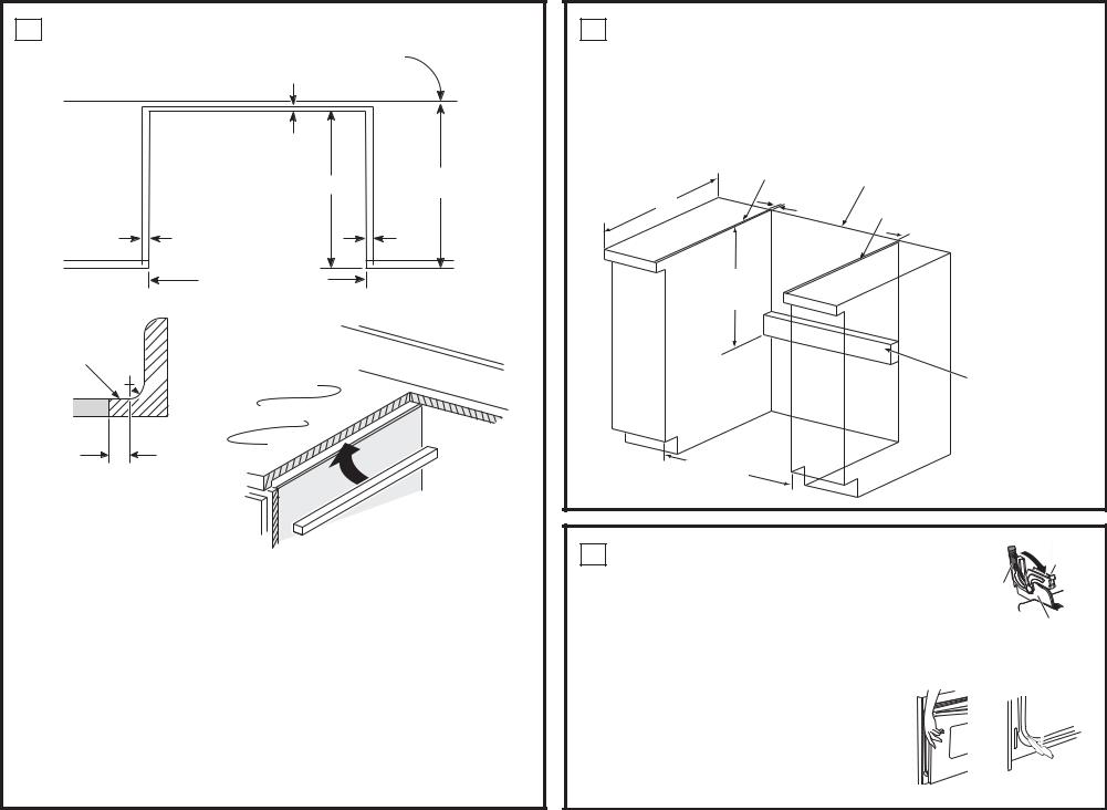
2 PREPARE THE OPENING (FOR INDOOR USE ONLY) (Continued)
Wall
|
1/4” min. flat |
|
|
23-3/16” |
25” |
|
typically |
|
|
|
|
9/16” min. |
|
9/16” min. |
flat |
|
flat |
29-15/16”– 30-1/16” smooth cut
Range support
Flat area
R

Countertop
1/4”
The Standard Installation of this Drop-In Range is to hang by the countertop on the side metal flanges under glass cooktop. This Range must not be installed on a base or sub structure (2”x 4” support).
If the construction of your cabinet cannot provide a 1/4” flat area at the back of the countertop opening, consider changing the countertop to accommodate this dimension. If the area is not flat, excess tension may be applied to the glass cooktop, causing breakage and voiding the warranty.
•Countertop thickness 1-1/4” min. is required to support the product. Braces must be installed between the underside of the countertop and the cabinet if required to obtain 1-1/4” minimum thickness (each side).
•Make sure the wall coverings, counters and cabinets around the oven can withstand the heat (up to 200° F (93.3° C) generated by the oven.
•This appliance has been approved for 0” spacing to adjacent surfaces above the cooktop. However, a 6” minimum spacing to surfaces less than 15” above the cooktop and adjacent cabinet is recommended to reduce exposure to steam, grease splatter and heat.
•Locate the wiring junction box at the rear of the cutout. The dimension from the top of the wiring junction box to the countertop must be a minimum of 28-1/2”. The box must not extend more than 3” off the plane of the wall. The junction box must be located where it will allow considerable slack in the range conduit, so that the range can be pulled out for service if necessary.
3 WHEN INSTALLING RANGE IN COUNTERTOP CUT OUT TO WALL
If the counter opening extends to the walls, it will require maintop filler kit WB07T1068X or backguard kit JXS32XX to close the gap. Refer to the filler or back guard kit instructions for installation details.
NOTE: If the countertop is greater than 25” it will show a gap between the back-guard and wall or between filler kit and the wall.
 WARNING: An additional anti-tip bracket support must be mounted to the rear wall of the cutout. The anti-tip bracket support is typically a 2x4 piece of lumber screwed directly into the wall studs. The anti-tip bracket support must be able to withstand 200 lbs of force at the engagement point.
Must be Flat
25”
9/16”
10-3/8” from countertop to anti-tip support
Wall
Must be Flat
 9/16”
9/16”
Anti-Tip Support
29-15/16” Min.
30-1/16” Max.
4 REMOVE OVEN DOOR
Door removal is not a requirement for installation of the product but is an added convenience. To remove the door:
1.Open the oven door as far as it will go.
2.Push both hinge locks toward the door frame to the unlocked position. This may require a flat blade screwdriver.
Hinge Lock
(Unlocked
Position)
Hinge 


Slot
Hinge Arm
3.Place hands on both sides of the door, and close the door to the removal position. This is half way between the broil stop and fully closed.
4.Lift the door up and out until the hinge arms clear the slots.
Hinge
Clears Slot

5 ELECTRICAL REQUIREMENTS
 WARNING Electric Shock Hazard
•This appliance must be properly grounded.
•Do not use an extension cord.
•Before installing range, switch power off at the service panel and lock the service disconnecting means to prevent power from being switched on accidentally. When the disconnection means cannot be locked, securely fasten a prominent warning device, such as a tag, to the service panel.
Failure to follow these instructions may result in serious injury or death.
 WARNING Fire Hazard
Improper connection of aluminum house wiring to copper leads can result in an electrical or fire hazard. If residence leads are aluminum, use only connectors designed for joining copper to aluminum and follow the manufacturer’s recommended procedure closely. Failure to do so may result in serious injury or death.
We recommend you have the electrical wiring and hookup of the appliance connected by a qualified electrician. After installation, have the electrician show you how to disconnect power from the appliance.
You must use a single-phase, 120/208 VAC or 120/240 VAC, 60 Hertz electrical system.
Effective January 1, 1996, the National Electrical Code requires that new construction (not existing) utilize a four-conductor connection to an electric oven. When installing an electric oven in new construction,
a mobile home, recreational vehicle or area where local codes prohibit grounding through the neutral conductor, refer to the section on four-conductor branch circuit connections.
Check with your local utilities for electrical codes which apply in your area. Failure to wire your oven according to governing code could result in a hazardous condition. If there are no local codes, your oven must be wired and fused to meet the National Electrical Code, NFPA No. 70-latest edition, available from the National Fire Protection Association.
Rating plate is located on oven front frame and is visible when oven door is open.
This appliance must supplied be with the proper voltage and frequency, and connected to an individual, properly grounded, 40 amp (minimum) branch circuit protected by a circuit breaker or time-delay fuse.
DO NOT shorten the flexible conduit. The conduit strain relief clamp must be securely attached to the junction box and the flexible conduit must securely attached to the clamp. If the flexible conduit will not fit within the clamp, do not install the oven until a clamp of the proper size is obtained.
The 3 power leads supplied with this appliance are suitable for connection to heavier gauge household wiring. The insulation of these 3 leads is rated for temperatures much higher than the temperature rating of the household wiring. The current-carrying capacity of the conductor is governed by the wire gauge and the temperature rating of the insulation around the wire.
MAKE ELECTRICAL CONNECTIONS
Place the unit on a platform or table even with the cutout opening. The platform must support 200 lbs. (91 kg). Connect the flexible conduit to the electrical junction box as follows:
THREE-CONDUCTOR BRANCH CIRCUIT CONNECTION
NOTE: If residence leads are aluminum conductors, see WARNING in section 5A, Electrical Requirements.
When connecting to a three-conductor branch circuit, if local codes permit:
1.Connect the oven ground conductor along with the neutral (white) lead to the branch circuit neutral (white or gray in color), using a wire nut.
2.Connect the oven red lead to the branch circuit red lead, and the oven black lead to the branch circuit black lead in accordance with local codes, using wire nuts.
3.Install proper strain relief clamp.
4.Install junction box cover.
Range conduit snaps into box
Red
Ground and  neutral wires (white)
Black
Branch circuit
 Alternate Tape or knockout Crimp
Neutral wire connection
5 ELECTRICAL REQUIREMENTS (Continued)
FOUR-CONDUCTOR BRANCH CIRCUIT CONNECTION
NOTE: If residence leads or ground are aluminum conductors, see WARNING in section 5A, Electrical Requirements.
When connecting to a four-conductor branch circuit, if local codes permit:
1.Free the neutral (white) lead from being restrained to any other wires. If necessary, cut the neutral (white) lead and then re-strip it to expose the proper length of conductor.
2.Attach the appliance grounding lead (green or bare copper) in accordance with local codes.
3.Connect the oven neutral (white) lead to the branch circuit neutral (white or gray) in accordance with local codes, using a wire nut.
4.Connect the oven red lead to the branch circuit red lead and the oven black lead to the branch circuit black lead in accordance with local codes, using wire nuts.
5.Install proper strain relief clamp.
6.Install junction box cover.
Black
Range conduit snaps into box
Red
White 
Branch circuit
Ground wires
Alternate knockout
6 ANTI-TIP DEVICE INSTALLATION
 WARNING
•To reduce the risk of tipping the range, the range must be properly secured to the countertop or rear wall using the anti-tip suppport. (See section 3 for details.)
•Weight on the door could potentially cause the range to tip and result in injury. Never allow anyone to climb, sit, stand, or hang on the oven door.
Installing the Anti-Tip |
ANTI-TIP INSTALLATION |
|
|
|||
|
Bracket |
Interior wall |
|
|
|
|
The anti-tip bracket is |
1/4” |
Wall stud |
|
|
||
attached to the back |
min. flat |
|
|
|
||
of the Drop-In Range. |
area |
|
|
|
||
It is designed to fit |
Maintop |
|
|
|
||
under the bottom |
|
Countertop |
|
|||
of the countertop |
|
|
||||
|
thickness |
|
||||
opening at the rear. |
Anti-tip |
|
|
|
||
Measure counter |
|
|
|
|||
thickness at back of |
bracket |
Bottom of |
|
|
||
|
|
|
||||
cutout to determine |
Bottom of |
countertop |
|
|
||
|
|
|
||||
correct bracket |
countertop |
|
|
|
||
to engage |
Wire cover |
|
|
|||
location. |
bracket by |
Interior wall |
Wall stud |
|||
|
||||||
Select the proper |
1/2” min. |
|
|
|
||
|
|
Non-kit application |
Countertop |
|||
position for the |
|
|
Maintop |
surface |
||
countertop thickness |
Anti-tip bracket location |
|
|
|
||
and move bracket to |
|
|
|
|||
(rear of range) |
|
|
10-3/8” |
|||
proper position. (Unit |
|
|
||||
Cooktop |
|
|
Wire |
|||
is supplied with brack- |
|
|
Attachment |
cover |
||
et in |
|
|
|
1-1/2” |
||
position 1.) |
|
|
Position |
|
||
1 For 1.18” (3 cm) |
|
|
#5 non-kit |
|
||
|
|
application |
|
|||
|
Counter |
|
|
|
Attachment |
|
2 |
For 1.5” Counter |
|
|
Anti-tip bracket |
anchored to |
|
|
|
wall stud is |
||||
|
|
|
||||
3 |
For 3.5” Counter |
|
|
*Attachment |
required |
|
|
|
|
||||
4 |
Alternate (shown) |
|
|
to engage |
|
|
|
|
bracket by 1/2” min. |
|
|||
31-11041 08-16 GEA
 Loading...