


JCK1000DF1BB
GE JCK1000DF1BB, JCK1000DF2BB, JCK1000SF1SS, JCK3000DF1BB, JCK3000DF1WW Installation Guide
...
Installation Instructions
27" & 30" Electric Built-in Wall Ovens
Questions? Calt 1.800.GE.CARES(1.800.432.2737) or visit www.GEAppiiances.com
In Canada, calt 1.800.561.3344 or visit www.GEAppliances.ca
BEFORE YOU BEGIN
Reed these instructions completelg end
cerefullg.
" IM PORTANT -- Save these instructions
for local inspector's use.
" IMPORTANT -- Observe allgoverning
codes and ordinances.
, Note to Installer- Be sure to leave these
instructions with Consumer.
ATTENTION INSTALLER: All electric wall ovens must be hard-wired (direct-wired)into an
approved junction box. A plug and receptacle is NOT permitted on these products.
FOR YOUR SAFETY:
WAR NING:Before beginning the installation, switch power off at the service panel and
lock the service disconnecting means to prevent power from being switched on accidentallg. When the
service disconnecting means cannot be locked, securelg fasten a prominent warning device, such as a tag,
to the service panel.
Besure the oven is securelg installed in a cabinet that is firmlg attached to the house structure.
Weight on the oven door could cause the oven to tip and result in injurg. Never allow angone to climb, sit,
stand or hang on the oven door.
Make sure the wall coverings, counters and cabinets around the oven can withstand the heat
(up to 200°F [93.3°C])generated bg the oven.
, Note to Consumer- Keepthese instructions
for future reference.
, Skill level- Installation of this appliance
requires a qualified installer or electrician.
. Proper installation is the responsibility
of the installer.
, Product failure due to improper installation
isnot covered under Warranty.
, Product is for indoor use onlg.
DESIGN INFORMATION
SINGLEOVEN INSTALLATIONS
The singleoven mag be installed in a cabinet alone or above a warming drawer. Thesingle oven meg also
be installed below a countertop or below specified cooktops. Seethe label ontop of the oven for approved
models.
DOUBLEOVENINSTALLATIONS
Adouble oven mag beinstalled in a cabinet alone or above a warming drawer. Seethe label on top of the
oven for approved models.
IMPORTANT:Alwagsreferto individualinstallationinstructionspackedwith eachproductfor specific
requirements.
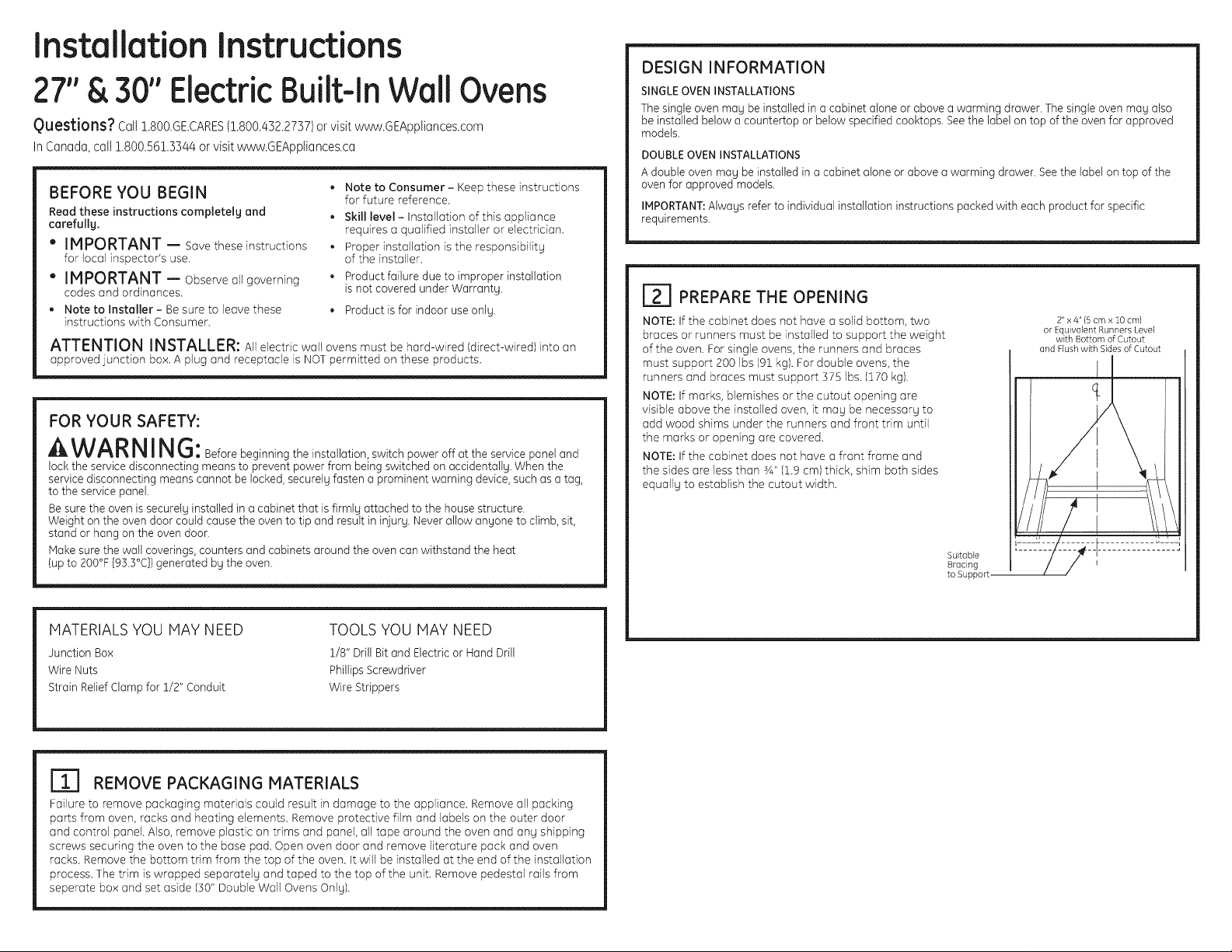
I_] PREPARE THE OPENING
NOTE: If the cabinet does not have a solid bottom, two
braces or runners must be installed to support the weight
of the oven. For single ovens, the runners and braces
must support 200 Ibs 191kg). For double ovens, the
runners and braces must support 375 Ibs. 1170kg).
NOTE: If marks, blemishes or the cutout opening are
visible above the installed oven, it mag be necessarg to
add wood shims under the runners and front trim until
the marks or opening are covered.
NOTE: If the cabinet does not have a front frame and
the sides are less than sA"11.9cm) thick, shim both sides
equallg to establish the cutout width.
Suitable
Bracing
to Support.
2" x 4"(5 cm x 10 cm)
or Equivalent Runners Level
with Bottom of Cutout
and Flush with Sides of Cutout
MATERIALS YOU MAY NEED
JunctionBox
Wire Nuts
Strain Relief Clamp for 1/2" Conduit
m
TOOLS YOU MAY NEED
1/8" Drill Bit and Electric or Hand Drill
PhillipsScrewdriver
Wire Strippers
Ill REMOVE PACKAGING MATERIALS
Failure to remove packaging materials could result in damage to the appliance. Remove all packing
parts from oven, racks and heating elements. Remove protective film and labels on the outer door
and control panel. Also, remove plastic on trims and panel, all tape around the oven and ang shipping
screws securing the oven to the base pad. Open oven door and remove literature pack and oven
racks. Remove the bottom trim from the top of the oven. It will be installed at the end of the installation
process. The trim is wrapped separatelg and taped to the top of the unit. Remove pedestal rails from
separate box and set aside (30" Double Wall Ovens Onlg).
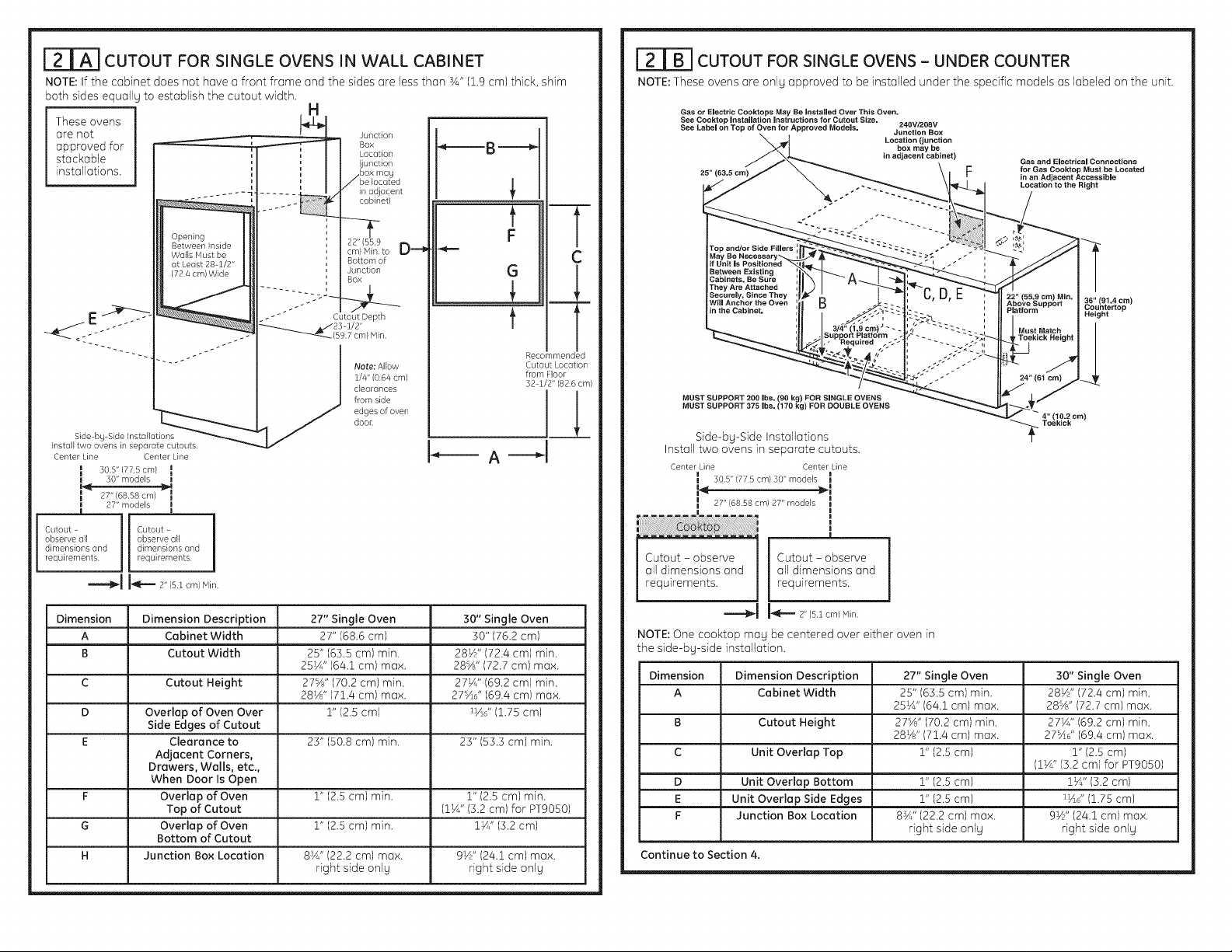
r_==_ CUTOUT FOR SINGLE OVENS IN WALL CABINET
NOTE: If the cabinet does not have a front frame and the sides are less than sA" (1.9 cm) thick, shim
both sides equally to establish the cutout width.
These ovens
are not
approved for
stackable
installations.
Opening
Between Inside
Wails Must be
at Least 28-1/2"
(724 cm) Wide
..... ~%:;, ....
Sideby-SideInstallations
Installtwo ovensinseparatecutouts
CenterLine CenterLine
] so.s"177scrnl ]
I 30"models I
] 2T' (68.58crn) ]
I 27"modes !
I !
Cutout- Cutout -
observeall observeall
dimensionsand dimensionsand
--I
requirements requirements
"---_1 I_== 2"Is1cm/r_in
H
Junction
Box
Location
(junction
box may
Jbe located
in adjacent
cabinetl
: --T
22" (559 __-=_lm
cm} Hin. to
_ Bottomof
J Junction
J BOX
J
-" " Cutou/Depth
(59.7cm} Nlin.
Note: Allow
1/4" (0.64 cm)
clearances
from side
edges of oven
door.
_____B___-_
t
F
G
............................... L ......
t
A---d
Recommended
Cutout Location
from Floor
32 1/2" (826 cm)
CUTOUT FOR SINGLE OVENS - UNDER COUNTER
NOTE: These ovens are only approved to be installed under the specific models as labeled on the unit.
Gas or Electric Cooktops May Be Installed Over This Oven.
See Cooktop Installation instructions for Cutout Size, 240V/208V
See Label on Top of Oven for Approved Models. Junction Box
25" (63.5 cm)
Location (junction
box may be
in adjacent cabinet)
Gas and Electrical Connections
for Gas Cooktop Must be Located
in an Adjacent Accessible
Location to the Right
C
m
4_
MUST SUPPORT 200 Ibs. (60 kg) FOR SINGLE OVENS
MUST SUPPORT 375 Ibs. (170 kg) FOR DOUBLE OVENS
Side-by-Side Installations
Install two ovens in separate cutouts.
center Line CenterLine
I 30.5" (775cm)30"models
JL
Cutout - observe
all dimensions and
requirements.
all dimensions and
Cutout = observe
requirements.
36" (91.4 cm)
Countertop
Height
Dimension Dimension Description 27" Single Oven 30" Single Oven
A Cabinet Width 27" (68.6 cm) 30" (76.2 cm)
B Cutout Width 25" (63.5 cm) min. 28½" (72.4 cm) min.
C Cutout Height 27%" (70.2 cm) min. 27½" (69.2 cm) min.
D Overlap of Oven Over 1" (2.5 cm) _¼_d'(1.75 cm)
E Clearance to 23" 150.8 cm) min. 23" 153.3 cm) min.
F Overlap of Oven 1" 12.5 cm) min. 1" 12.5 cm) min.
G Overlap of Oven 1" (2.5 cm) min. 1½" (3.2 cm)
H Junction Box Location 8¾" (22.2 cm) max. 9½" (24.1 cm) max.
Side Edges of Cutout
Adjacent Corners,
Drawers, Walls, etc.,
When Door Is Open
Top of Cutout (11/4'' 13.2 cm) for PT9050)
Bottom of Cutout
25½" (64.1 cm) max. 28sA " (72.7 cm) max.
28½" (71.4 cm) max. 27s4d ' (69.4 cm) max.
right side only right side only
__q
_=2" (5.lcm)Nlin.
NOTE:One cooktop may be centered over either oven in
the side-by-side installation.
Dimension Dimension Description 27" Single Oven 30" Single Oven
A Cabinet Width 25" (63.5 cm) min. 28½" (72.4 cm) min.
B Cutout Height 27%" (70.2 cm) min. 27½" (69.2 cm) min.
C Unit Overlap Top 1" (2.5 cm) 1" (2.5 cm)
D Unit Overlap Bottom 1" (2.5 cm) l_/J ' (5.2 cm)
E Unit Overlap Side Edges 1" (2.5 cm) _¼_d'(1.75 cm)
F Junction Box Location 8sA" (22.2 cm) max. 9½" (24.1 cm) max.
Continue to Section 4.
25¼" (64.1 cm) max. 28%" (72.7 cm) max.
28½" (71.4 cm) max. 27%d' (69.4 cm) max.
(1VJ' (5.2 cm) for PT9050)
right side only right side only
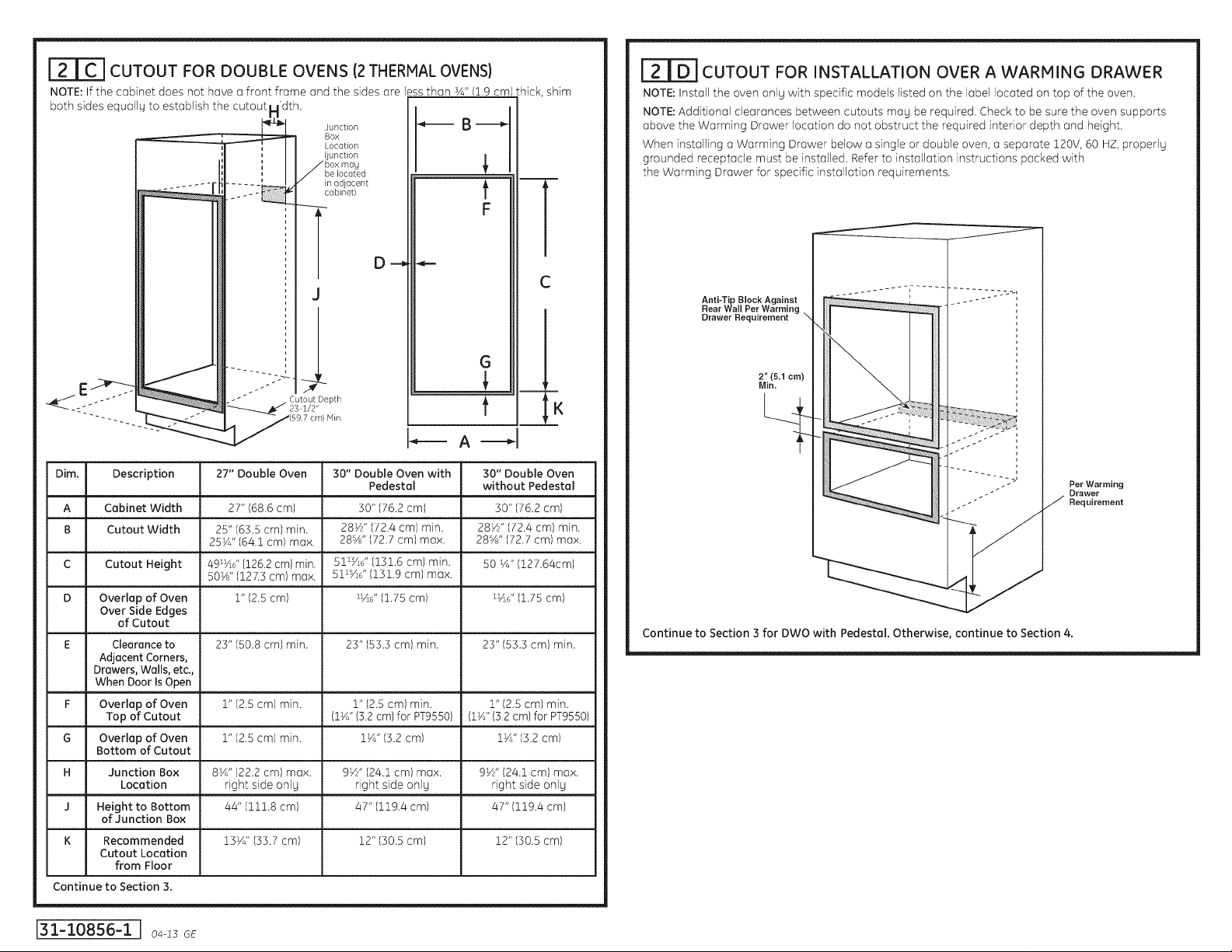
CUTOUT FOR DOUBLE OVENS (2THERMAL OVENS)
NOTE: If the cabinet does not have a front frame and the sides are less than sA"(1.9 cm)
Junction
BO×
Location
both sides equall_h.i
(junction
/ boxmay
/be located
in adjacent
cabinet)
t
F
hick, shim
i
CUTOUT FOR INSTALLATION OVER A WARMING DRAWER
NOTE: Installtheoven onlywithspecificmodelslistedon the labellocatedon topofthe oven.
NOTE: Additionalclearancesbetween cutoutsmay be required.Checktobe suretheoven supports
above theWorming Drawer locationdo notobstructtherequiredinteriordepth and height.
When installinga Worming Drawer belowa singleordoubleoven,a separate120V,60HZ,properly
grounded receptaclemust be installed.Refertoinstallationinstructionspocked with
theWorming Drawer forspecificinstallationrequirements.
l
O _
J
G
r
t
Dim. Description 27" Double Oven 30" Double Oven with 30" Double Oven
A Cabinet Width 27" (68.6 am) 30" (76.2 am) 30" (76.2 am)
B Cutout Width 25" (63.5 cm) min. 28½" (72.4 cm) min. 28½" (72.4 cm) min.
C Cutout Height 4%_d' (126.2cm) min. 5113/S' (131.6 cm) min. 50 ¼" (127.64cm)
D Overlap of Oven 1" (2.5am) _½d'(1.75 am) _4d' (1.75 am)
Over Side Edges
of Cutout
E Clearanceto 23" (50.8 cm) min. 23" (53.3 cm) min. 23" (53.3 cm) min.
Adjacent Corners,
Drawers, Walls, etc.,
When Door/sOpen _ ,
F Overlap of Oven 1" (2.5 am) rain. 1" (2.5 cm) min. 1" (2.5 cm) min.
Top of Cutout (1¼"(5.2cm) for PT9550) (1¼"(5.2cm) for PT9550)
G Overlap of Oven 1" (2.5 cm) min. 11/4"(5.2 cm) 11/4"(5.2cm)
Bottom of Cutout
H Junction Box 8sA" (22.2 cm) max. 9½" (24.1 cm) max. 9½" (24.1 cm) max.
Locat!on _ rights!de only _ rights!de only . rights!de only
J Height to Bottom 44" (111.8cm) 47" (i19.4cm) 47" (i19.4cm)
of Junction Box
K Recommended 15¼" (55.7 am) 12" (50.5 am) 12" (50.5 am)
Cutout Location
from Floor
Continue to Section 3.
25¼" (64.1cm) max. 28%" (72.7 cm) max. 28%" (72.7 cm) max.
50½" (127.5 am) max. 51_/_d' (151.9 am) max.
Pedestal without Pedestal
%
r
i
Anti-Tip Block Against
Rear Wall Per Warming
Drawer Requirement
2" (5.1 cm)
Min.
Continue to Section 3 for DWO with Pedestal. Otherwise, continue to Section 4.
Per Warming
Drawer
Requirement
J31-i0856-iJo -isGE
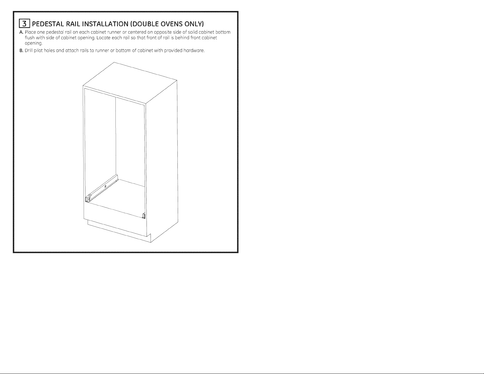
_-I PEDESTAL RAIL INSTALLATION (DOUBLE OVENS ONLY)
A. Place one pedestal rail on each cabinet runner or centered on opposite side of solid cabinet bottom
flush with side of cabinet opening. Locate each rail so that front of rail is behind front cabinet
opening.
B. Drill pilot holes and attach rails to runner or bottom of cabinet with provided hardware.
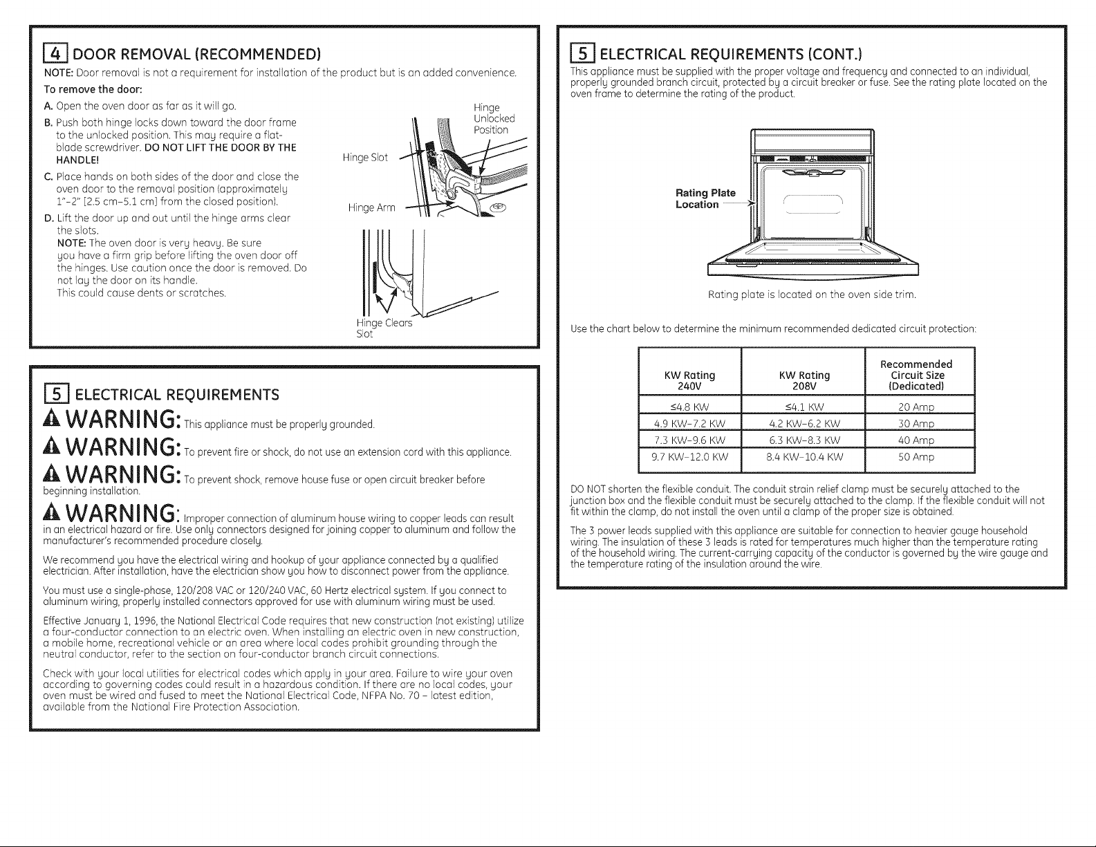
[_ DOOR REMOVAL {RECOMMENDED)
NOTE: Door removal is not a requirement for installation of the product but is an added convenience.
To remove the door:
A. Open the oven door as far as it will go.
B. Push both hinge locks down toward the door frame
to the unlocked position. This may require a flat-
blade screwdriver. DO NOT LIFTTHE DOOR BYTHE
HANDLE!
C. Place hands on both sides of the door and close the
oven door to the removal position (approximately
1"-2" [2.5 cm-5.1 cm] from the closed position).
D. Lift the door up and out until the hinge arms clear
the slots.
NOTE: The oven door is very heavy. Be sure
you have a firm grip before lifting the oven door off
the hinges. Use caution once the door is removed. Do
not lay the door on its handle.
This could cause dents or scratches.
_1_ Unlocked
Hinge Slot ,
Hinge Arm
Hinge
Position
[_] ELECTRICAL REQUIREMENTS {CONT.)
Thisappliance must be supplied with the proper voltage and frequency and connected to an individual,
properly grounded branch circuit, protected by a circuit breaker or fuse. See the rating plate located on the
oven frame to determine the rating of the product•
_================_ _
Rating Plata
Location ....................................;
Rating plate is located on the oven side trim.
Hinge Clears
Slot
r_ ELECTRICAL REQUIREMENTS
A WARNING:This appliance rnust be properly grounded
A WAR N I N G: To prevent fire or shock, do not use an extension cord with this appliance.
A WA R N I N G: To prevent shock, remove house fuse or open circuit breaker before
beginning installation.
A WAR N IN G: ,mproperconnectionofa,uminumhousewiring to copper leads can result
in an electrical hazard or fire. Useonly connectors designed for joining copper to aluminum and follow the
manufacturer's recommended procedure closely.
We recommend you have the electrical wiring and hookup of your appliance connected by a qualified
electrician. After installation, have the electrician show you how to disconnect power from the appliance.
You must use a single-phase, 120/208 VACor 120/240 VAC,60 Hertz electrical system. If you connect to
aluminum wiring, properly installed connectors approved for use with aluminum wiring must be used.
Effective Januarg 1, 1996, the National Electrical Code requires that new construction (not existing) utilize
a four-conductor connection to an electric oven. When installing an electric oven in new construction,
a mobile home, recreational vehicle or an area where local codes prohibit grounding through the
neutral conductor, refer to the section on four-conductor branch circuit connections.
Check with your local utilities for electrical codes which apply in your area. Failure to wire your oven
according to governing codes could result in a hazardous condition. If there are no local codes, your
oven must be wired and fused to meet the National Electrical Code, NFPA No. 70 i latest edition,
available from the National Fire Protection Association.
Use the chart below to determine the minimum recommended dedicated circuit protection:
KW Rating KW Rating Circuit Size
240V 208V {Dedicated)
<4.8 KW <4.2 KW 20 Amp
4.9 KW=7.2 KW 4.2 KW=6.2 KW 30 Amp
7.3 KW-9.6 KW 6.3 KW-8.3 KW 40 Amp
9.7 KW-12.0 KW 8.4 KW-10.4 KW 50 Amp
DO NOTshorten the flexible conduit. The conduit strain relief clamp must be securely attached to the
junction box and the flexible conduit must be securely attached to the clamp. If the flexible conduit will not
fit within the clamp, do not install the oven until a clamp of the proper size isobtained•
The 3 power leads supplied with this appliance are suitable for connection to heavier gauge household
wiring. The insulation of these 3 leads israted for temperatures much higher than the temperature rating
of the household wiring. Thecurrent-carrying capacity of the conductor is governed by the wire gauge and
the temperature rating of the insulation around the wire.
Recommended
 Loading...