

Garmin GA Installation Instructions Manual

Remote GPS Antenna Installation Instructions.................................................................................. 2
TA-2013/783
Instructions d'installation de l'antenne GPS externe.......................................................................... 5
Istruzioni di installazione dell'antenna GPS esterna.......................................................................... 8
Externe GPS-Antenne – Installationsanweisungen......................................................................... 11
Instrucciones de instalación de la antena GPS remota................................................................... 14
Instruções de Instalação da Antena de GPS Remota..................................................................... 17
Installatie-instructies voor externe GPS-antenne.............................................................................20
Vejledning til installation af GPS-fjernantenne................................................................................. 23
GPS-etäantennin asennusohjeet..................................................................................................... 26
Installeringsinstruksjoner for ekstern GPS-antenne.........................................................................28
Installationsinstruktioner för fjärrmonterad GPS-antenn.................................................................. 31
Instrukcja instalacji zdalnej anteny GPS.......................................................................................... 34
远程 GPS 天线安装说明...................................................................................................................37
®
Garmin
and the Garmin logo are trademarks of Garmin Ltd. or its subsidiaries, registered in the USA and other countries. These trademarks may not be used without the express permission of Garmin.
El número de registro COFETEL/IFETEL puede ser revisado en el manual a través de la siguiente página de internet.
March 2016 190-01139-91_0BPrinted in Taiwan
Remote GPS Antenna Installation
Instructions
WARNING
See the Important Safety and Product Information guide in the
GPS device product box for product warnings and other
important information.
CAUTION
Always wear safety goggles, ear protection, and a dust mask
when drilling, cutting, or sanding.
NOTICE
When drilling or cutting, always check what is on the opposite
side of the surface.
This antenna can be installed to provide a stronger GPS signal
to a compatible Garmin® chartplotter. This antenna uses a BNC
connector to connect to the port labeled ANTENNA or EXT GPS
on a compatible Garmin chartplotter.
Antenna Mounting Considerations
You can mount the antenna on a flat surface, install it under
fiberglass, or attach it to a standard 1 in. OD, 14 threads per
inch, pipe-threaded pole (not included). You can route the cable
outside of the pole or through the pole. For optimal performance,
consider these guidelines when selecting the antenna mounting
location.
• To avoid interference with a magnetic compass, the antenna
should not be mounted closer to a compass than the
compass-safe distance value listed in the product
specifications.
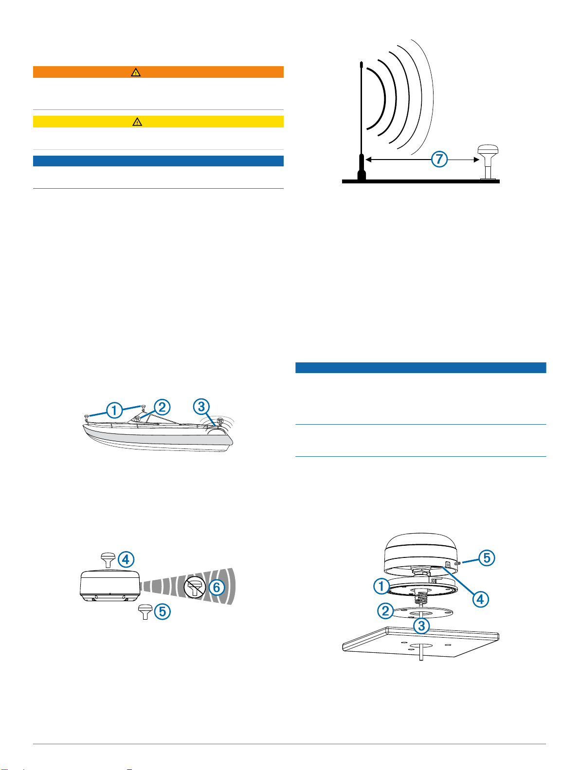
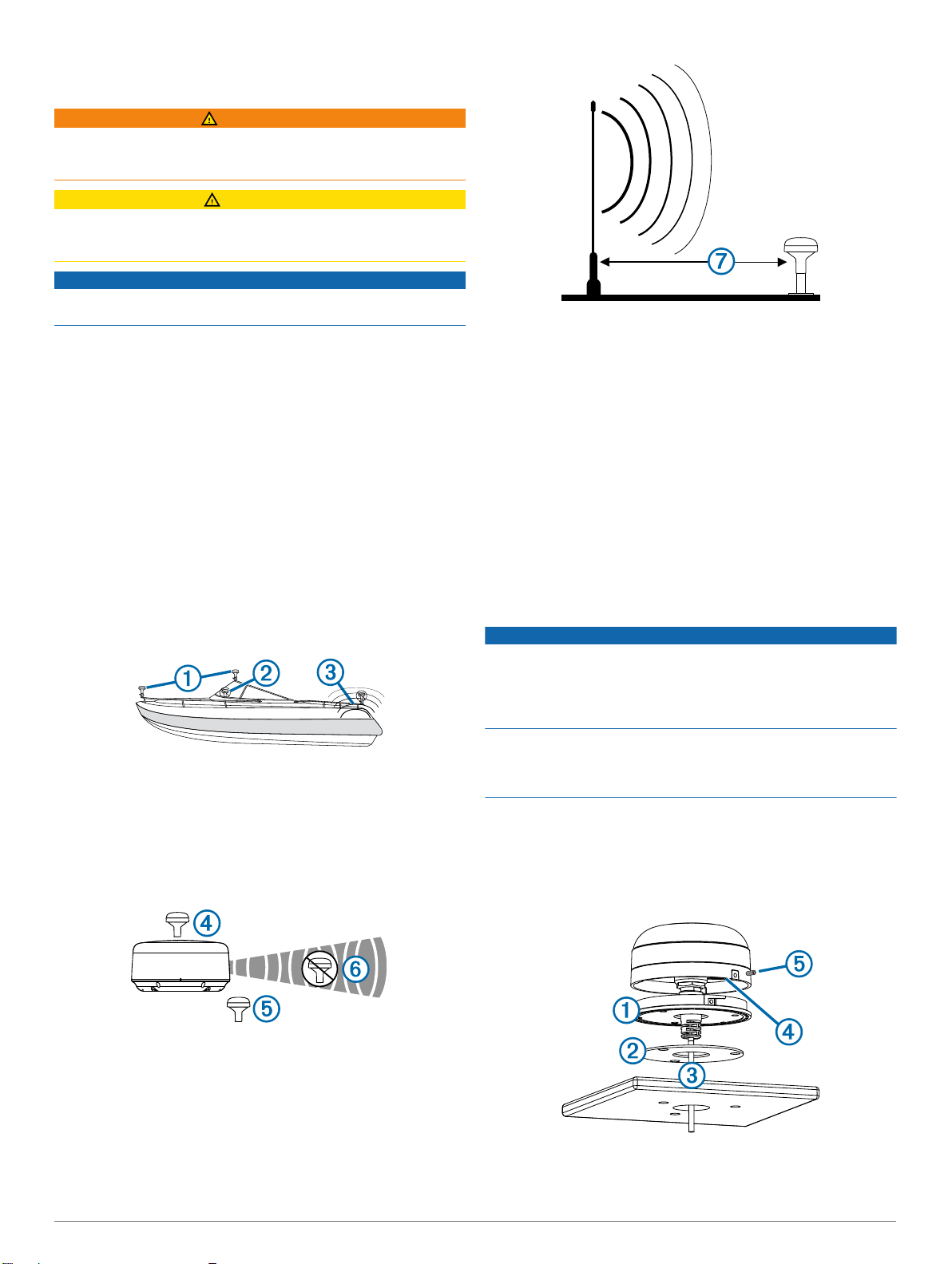
• To ensure the best reception, the antenna should be
mounted in a location that has a clear, unobstructed view of
the sky in all directions À.
• On a sailboat, to prevent inaccurate speed readings caused
by excessive heeling, the antenna should not be mounted
high on the mast.
• The antenna provides more-stable readings when located
nearer to water level.
Testing the Mounting Location
Temporarily secure the antenna in the preferred mounting
1
location and test it for correct operation.
If you experience interference with other electronics, move
2
the antenna to a different location, and test it again.
Repeat steps 1–2 until you observe full or acceptable signal
3
strength.
Permanently mount the antenna.
4
Surface Mounting the Antenna
NOTICE
If you are mounting the bracket on fiberglass with screws, it is
recommended to use a countersink bit to drill a clearance
counterbore through only the top gel-coat layer. This will help to
avoid any cracking in the gel-coat layer when the screws are
tightened.
Stainless-steel screws may bind when screwed into fiberglass
and overtightened. Garmin recommends applying an anti-seize
lubricant to the screws before installing them.
• The antenna should not be mounted where it is shaded by
the superstructure of the boat Á, a radome antenna, or the
mast.
• The antenna should not be mounted near the engine or other
sources of Electromagnetic Interference (EMI) Â.
• If a radar is present, the antenna should be mounted above
the path of the radar Ã. If necessary, the antenna may be
mounted below the path of the radar Ä.
• The antenna should not be mounted directly in the path of the
radar Å.
• The antenna should be mounted at least 3 ft. (1 m) away
from (preferably above) the path of a radar beam or a VHF
radio antenna Æ.
2 Installation Instructions
Before you permanently mount the antenna, you must test the
mounting location for correct operation (Testing the Mounting
Location, page 2).
Using the surface-mount bracket À as your mounting
1
template, mark the three pilot-hole locations and trace the
cable-hole in the center of the bracket.
Set the surface-mount bracket aside.
2
Do not drill through the bracket.
Drill the three 3.2 mm (1/8 in.) pilot holes.
3
Use a 25 mm (1 in.) hole saw to cut the cable hole in the
4
center.
Place the seal pad Á on the bottom of the surface-mount
5
bracket, aligning the screw holes.
Use the included M4 screws to secure the surface-mount
6
bracket to the mounting surface.
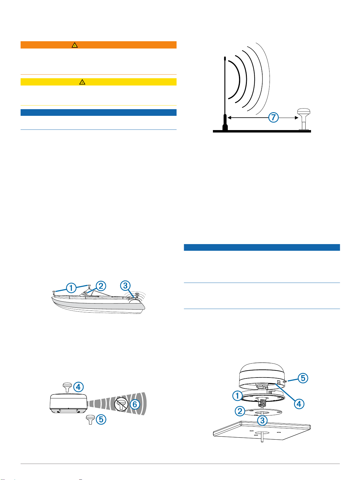
Route the cable  through the 25 mm (1 in.) hole and
7
connect it to the antenna.
Verify the large gasket à is in place on the bottom of the
8
antenna, place the antenna on the surface-mount bracket,
and twist it clockwise to lock it in place.
Secure the antenna to the mounting bracket with the included
9
M3 set screw Ä.
Route the cable away from sources of electronic interference.
10
Mounting the Antenna with the Cable Routed Outside the Pole
Before you permanently mount the antenna, you must test the
mounting location for correct operation (Testing the Mounting
Location, page 2).
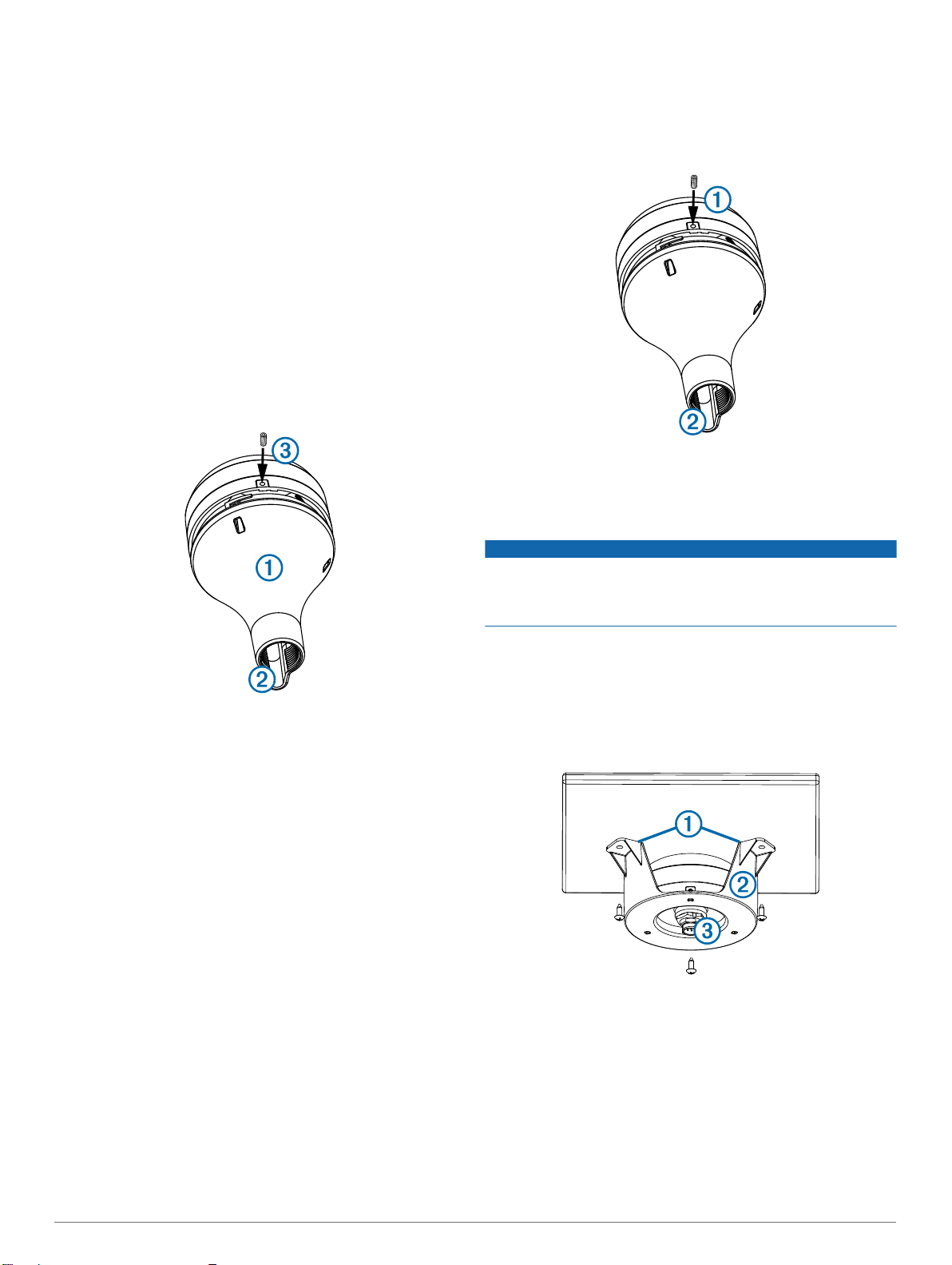
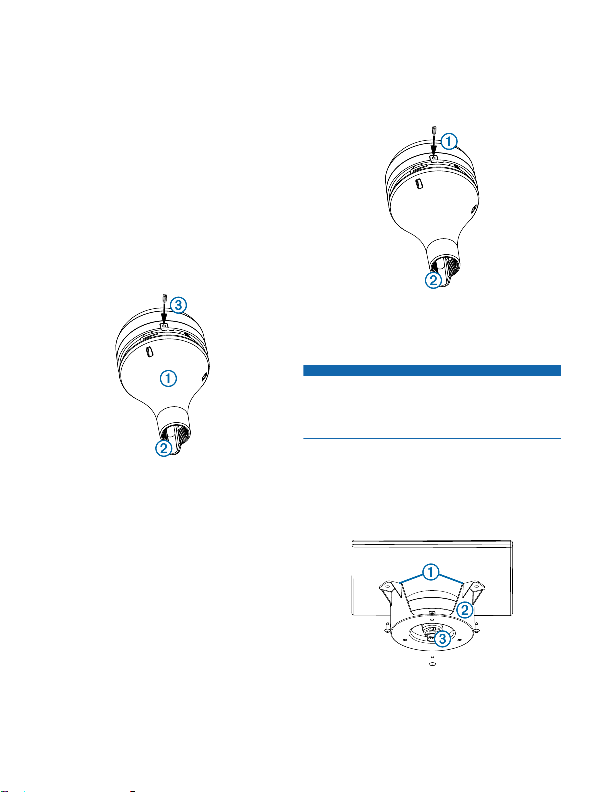
Route the cable through the pole-mount adapter À, and
1
place the cable in the vertical slot Á along the base of the
pole-mount adapter.
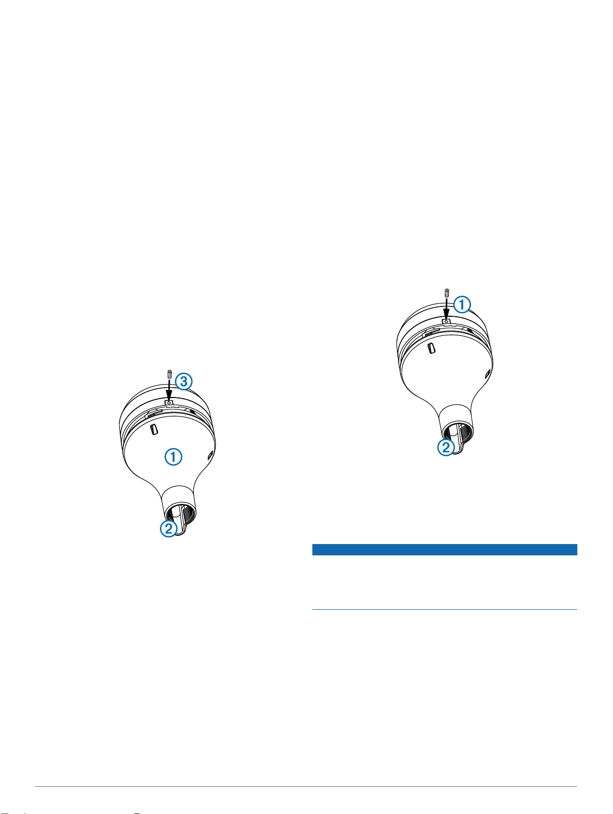
Route the cable through the pole and connect it to the
5
antenna.
Place the antenna on the pole-mount adapter and twist it
6
clockwise to lock it in place.
Secure the antenna to the adapter with the included M3 set
7
screw À.
With the antenna installed on the pole mount, fill the vertical
8
cable slot Á with a marine sealant (optional).
Route the cable away from sources of electronic interference.
9
Mounting the Antenna Under the Deck
Screw the pole-mount adapter onto a standard 1 in. OD, 14
2
threads per inch, pipe-threaded pole (not included).
Do not overtighten the adapter on the pole.
Connect the cable to the antenna.
3
Place the antenna on the pole-mount adapter and twist it
4
clockwise to lock it in place.
Secure the antenna to the adapter with the included M3 set
5
screw Â.
With the antenna installed on the pole mount, fill the
6
remaining gap in the vertical cable slot with a marine sealant
(optional).
Attach the pole to the boat if it is not already attached.
7
Route the cable away from sources of electronic interference.
8
Mounting the Antenna with the Cable Routed Through the Pole
Before you permanently mount the antenna, you must test the
mounting location for correct operation (Testing the Mounting
Location, page 2).
Position a standard 1 in. OD, 14 threads per inch, pipe-
1
threaded pole (not included) in the selected location, and
mark the approximate center of the pole.
Drill a hole using a 19 mm (3/4 in.) drill bit for the cable to
2
pass through.
Fasten the pole to the boat.
3
Thread the pole-mount adapter onto the pole.
4
Do not overtighten the adapter.
NOTICE
Before attaching the under-deck mounting bracket to the
surface, verify the included screws will not penetrate the
surface. If the included screws are too long, you must purchase
surface-appropriate screws to complete the installation.
Before you permanently mount the antenna, you must test the
mounting location for correct operation (Testing the Mounting
Location, page 2).
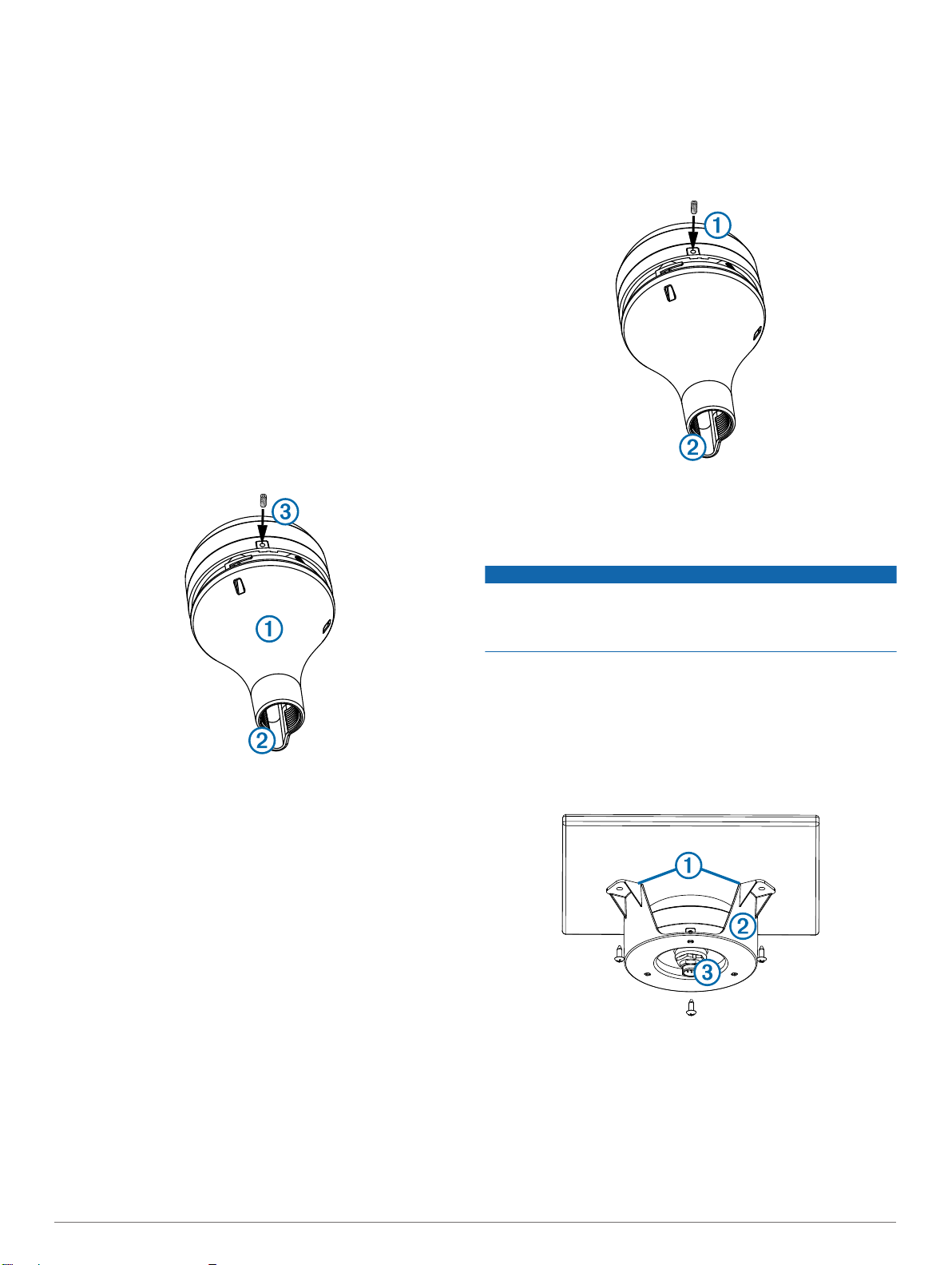
Because the antenna cannot acquire signals through metal, it
must be mounted under a fiberglass surface only.
Place the adhesive pads À on the under-deck mounting
1
bracket Á.
Place the antenna in the under-deck mounting bracket.
2
Adhere the under-deck mounting bracket to the mounting
3
surface.
Secure the under-deck mounting bracket to the mounting
4
surface with screws.
Connect the cable to the antenna Â.
5
Route the cable away from sources of electronic interference.
6
Installation Instructions 3

Specifications
Measurement Specification
Dimensions (diameter x
height)
Weight 7.1 oz (201 g)
Temperature range -22° to 176°F (-30° to 80°C)
Case material Fully gasketed, high-impact plastic alloy
Water rating IEC 60529 IPX7
Compass-safe distance 114 mm (4.5 in.)
319/32 × 115/16 in. (91.6 × 49.5 mm)
4 Installation Instructions
Instructions d'installation de l'antenne
GPS externe
AVERTISSEMENT
Consultez le guide Informations importantes sur le produit et la
sécurité inclus dans l'emballage du GPS pour prendre
connaissance des avertissements et autres informations sur le
produit.
ATTENTION
Portez toujours des lunettes de protection, un équipement
antibruit et un masque anti-poussière lorsque vous percez,
coupez ou poncez.
AVIS
Lorsque vous percez ou coupez, commencez toujours par
vérifier la nature de la face opposée de l'élément.
• L'antenne doit être montée à au moins 3 pieds (1 m), et de
préférence au-dessus, de la trajectoire d'un faisceau radar ou
d'une antenne radio VHF Æ.
Cette antenne peut être installée pour fournir un signal GPS
plus puissant à un traceur Garmin compatible. Cette antenne
nécessite un connecteur BNC pour être connectée au port
nommé ANTENNA ou EXT GPS sur un traceur Garmin
compatible.
Considérations relatives au montage de l'antenne
Vous pouvez fixer votre antenne à plat pont, à une rotule avec
une tige filetée standard d'1 pouce de diamètre externe à
14 filetages par pouce (tige non fournie), ou l'installer sous le
roof du bateau. Vous pouvez faire passer le câble dans la rotule
ou à l'extérieur de celle-ci. Pour obtenir des performances
optimales, tenez compte de ces principes lors du choix de
l'emplacement de montage de l'antenne.
• Pour éviter toute interférence avec un compas magnétique,
l'antenne doit être installée à la distance de sécurité au
compas indiquée dans les caractéristiques techniques du
produit.
• Pour assurer la meilleure réception possible, montez
l'antenne à un endroit offrant une vue totalement dégagée
sur le ciel dans toutes les directions À.
• Sur un voilier, pour éviter les lectures de vitesse inexactes
liées à une gîte excessive, l'antenne ne doit pas être montée
trop haut sur le mât.
• L'antenne fournit des mesures plus stables lorsqu'elle est
placée près de la surface de l'eau.
Test de l'emplacement de montage
Fixez temporairement l'antenne à son emplacement
1
d'installation et testez son fonctionnement.
Si vous constatez une interférence avec d'autres appareils
2
électroniques, déplacez l'antenne et réessayez.
Répétez les étapes 1 et 2 jusqu'à recevoir une force de
3
signal optimale ou acceptable.
Montez définitivement l'antenne.
4
Montage de l'antenne à plat pont
AVIS
Si vous montez le support de montage sur de la fibre de verre
avec des vis, nous vous recommandons d'utiliser un foret de
fraisage pour percer un trou à fond plat à travers le revêtement
de la couche supérieure. De cette manière, vous ne risquez pas
de fissurer le revêtement au moment du serrage des vis.
Les vis en acier inoxydable risquent de se gripper lorsqu'elles
sont vissées dans la fibre de verre et qu'elles sont serrées outre
mesure. Garmin conseille d'appliquer un lubrifiant antigrippant
sur chaque vis avant installation.
Avant de monter définitivement l'antenne, testez son bon
• L'antenne ne doit pas être montée à un endroit où la
structure du bateau Á, l'antenne radôme ou le mât lui font de
l'ombre.
• L'antenne ne doit pas être montée à proximité du moteur ou
d'autres sources d'interférences électromagnétiques Â.
• Si le bateau est équipé d'un radar, il est préférable d'installer
l'antenne au-dessus de la trajectoire du faisceau radar Ã. Il
est toutefois acceptable de l'installer sous la trajectoire du
faisceau radar si nécessaire Ä.
• L'antenne ne doit pas être installée directement sur la
trajectoire du faisceau radar Å.
Instructions d'installation 5
fonctionnement à cet emplacement (Test de l'emplacement de
montage, page 5).
En vous servant du support de montage à plat pont
1
comme modèle de montage, marquez l'emplacement des
trois trous d'implantation et tracez l'orifice du câble au centre
du support.
Mettez de côté le support de montage à plat pont.
2
À
Ne percez pas à travers le support.
Percez les trois trous d'implantation de 3,2 mm (1/8 po).
3
Utilisez une scie à cloche de 25 mm (1 po) pour percer
4
l'orifice du câble au centre.
Placez le tampon d'étanchéité Á en bas du support de
5
montage à plat pont, en veillant à aligner les orifices des vis.
Utilisez les vis M4 fournies pour fixer le support de montage
6
sur la surface de montage.
Faites passer le câble  à travers l'orifice du câble de 25 mm
7
(1 po) et branchez-le à l'antenne.
Assurez-vous que le grand joint à est fixé au bas de
8
l'antenne, placez l'antenne sur le support de montage à plat
pont et tournez-la dans le sens des aiguilles d'une montre
pour la bloquer.
Fixez l'antenne au support de montage à l'aide de la vis M3
9
fournie Ä.
Eloignez le câble des sources d'interférences électroniques.
10
Montage de l'antenne sur rotule (câble à l'extérieur)
Avant de monter définitivement l'antenne, testez son bon
fonctionnement à cet emplacement (Test de l'emplacement de
montage, page 5).
Passez le câble dans la rotule de fixation À et placez-le dans
1
la fente verticale Á, le long de la base de l'adaptateur.
Vissez l'adaptateur de fixation sur rotule à la rotule.
4
Ne serrez pas l'adaptateur outre mesure.
Acheminez le câble à l'intérieur de la rotule et branchez-le à
5
l'antenne.
Placez l'antenne sur l'adaptateur de fixation et tournez-la
6
dans le sens des aiguilles d'une montre pour la bloquer.
Fixez l'antenne à l'adaptateur à l'aide de la vis M3 fournie À.
7
Une fois l'antenne installée, comblez la fente verticale Á du
8
câble à l'aide d'un mastic d'étanchéité (facultatif).
Eloignez le câble des sources d'interférences électroniques.
9
Montage de l'antenne sous le pont
Vissez l'adaptateur de fixation sur une rotule avec une tige
2
filetée standard d'un pouce de diamètre externe à
14 filetages par pouce (tige non fournie).
Ne serrez pas outre mesure.
Branchez le câble à l'antenne.
3
Placez l'antenne sur l'adaptateur de fixation et tournez-la
4
dans le sens des aiguilles d'une montre pour la bloquer.
Fixez l'antenne à l'adaptateur à l'aide de la vis M3 Â fournie.
5
Une fois l'antenne installée, comblez la fente verticale du
6
câble à l'aide d'un mastic d'étanchéité (facultatif).
Fixez la rotule sur le bateau, si ce n'est pas déjà fait.
7
Eloignez le câble des sources d'interférences électroniques.
8
Montage de l'antenne sur rotule (câble à l'intérieur)
Avant de monter définitivement l'antenne, testez son bon
fonctionnement à cet emplacement (Test de l'emplacement de
montage, page 5).
Placez une rotule avec tige filetée standard d'un pouce de
1
diamètre externe à 14 filetages par pouce (tige non fournie) à
l'emplacement sélectionné et faites une marque
approximativement au centre de la rotule.
Percez un trou à l'aide d'un foret de 19 mm (3/4 po) pour
2
permettre le passage du câble.
Fixez la rotule au bateau.
3
AVIS
Avant de fixer le support de montage sous le pont, assurez-vous
que les vis fournies ne transpercent pas le support. Si les vis
fournies sont trop longues, vous devez acheter des vis
appropriées au support pour terminer l'installation.
Avant de monter définitivement l'antenne, testez son bon
fonctionnement à cet emplacement (Test de l'emplacement de
montage, page 5).
L'antenne n'étant pas capable d'acquérir des signaux à travers
le métal, elle ne doit être montée que sous un support en fibre
de verre.
Placez les éléments adhésifs À sur le support de montage
1
sous le pont Á.
Placez l'antenne dans le support de montage sous le pont.
2
Faites adhérer le support de montage sous le pont à la
3
surface de montage.
A l'aide de vis, fixez le support de montage sous le pont à la
4
surface de montage.
Branchez le câble à l'antenne Â.
5
Eloignez le câble des sources d'interférences électroniques.
6
6 Instructions d'installation

Caractéristiques techniques
Mesure Caractéristique
Dimensions (diamètre ×
hauteur)
Poids 201 g (7,1 onces)
Plage de températures -22 à 176 °F (-30 à 80 °C)
Matériau du boîtier Alliage plastique résistant aux chocs,
Résistance à l'eau CEI 60529 IPX7
Distance de sécurité du
compas
3 19/32 × 1 15/16 po (91,6 × 49,5 mm)
hermétiquement fermé
114 mm (4,5’’)
Instructions d'installation 7
Istruzioni di installazione dell'antenna
GPS esterna
AVVERTENZA
Per avvisi sul prodotto e altre informazioni importanti, consultare
la guida Informazioni importanti sulla sicurezza e sul prodotto
inclusa nella confezione del dispositivo GPS.
ATTENZIONE
Durante le operazioni di foratura, taglio o carteggiatura,
indossare degli occhiali protettivi, una maschera antipolvere e
un'adeguata protezione per l'udito.
AVVISO
Prima di effettuare fori o tagli verificare l'eventuale presenza di
oggetti nel lato opposto della superficie da tagliare.
È possibile installare questa antenna per fornire un segnale
GPS più potente a un chartplotter Garmin compatibile.
L'antenna utilizza un connettore BNC per collegarsi alla porta
ANTENNA o EXT GPS su un chartplotter Garmin compatibile.
Considerazioni sull'installazione dell'antenna
È possibile installare l'antenna su una superficie piana,
sottocoperta oppure su un'asta da 1 poll. (14 filetti per pollice,
non in dotazione). È possibile far passare il cavo all'esterno o
attraverso l'asta. Per avere prestazioni ottimali, tenere in
considerazione le presenti istruzioni quando si sceglie le
posizione in cui montare l'antenna.
• Per evitare interferenze installare l'antenna lontano da una
bussola magnetica.
• Per garantire una ricezione ottimale, l'antenna deve essere
montata in una posizione tale che abbia una chiara visione
del cielo À.
• L'antenna non deve essere montata in posizioni in cui
potrebbe essere coperta da altre parti dell'imbarcazione Á,
dall'antenna radar o dall'albero.
• L'antenna non deve essere montata in prossimità del motore
o di altre sorgenti di interferenze elettromagnetiche (EMI) Â.
• In presenza di un radar, montare l'antenna sopra il fascio di
trasmissione del radar Ã. Se necessario, l'antenna può
essere montata sotto il fascio di trasmissione del radar Ä.
• Sulle imbarcazioni a vela, per impedire che la lettura della
velocità risulti imprecisa a causa dell'eccessiva inclinazione,
l'antenna non deve essere montata nella parte alta
dell'albero.
• L'antenna fornisce letture più stabili se posizionata in
prossimità del livello dell'acqua.
Verifica della posizione di montaggio
Fissare temporaneamente l'antenna nella posizione prescelta
1
e verificarne il corretto funzionamento.
Se si verificano interferenze con altri dispositivi elettronici,
2
spostare l'antenna in un'altra posizione e verificarne
nuovamente il funzionamento.
Ripetere i passi 1–2 finché la potenza del segnale non è
3
piena o accettabile.
Fissare l'antenna in modo permanente.
4
Montaggio dell'antenna a filo
AVVISO
Se si sta installando la staffa su fibra di vetro con delle viti, si
consiglia di utilizzare una punta fresatrice per praticare una
svasatura attraverso lo strato di resina. In questo modo è
possibile evitare crepe prodotte dal serraggio delle viti nello
strato di resina.
Le viti in acciaio inossidabile possono bloccarsi se vengono
avvitate e serrate più del necessario all'interno della fibra di
vetro. Garmin raccomanda di applicare alle viti un lubrificante
antigrippaggio prima dell'installazione.
Prima di montare l'antenna in modo definitivo, è necessario
verificare la posizione di montaggio per il corretto funzionamento
(Verifica della posizione di montaggio, pagina 8).
Utilizzare la staffa per il montaggio a filo À come dima,
1
segnare le posizioni dei tre fori di riferimento e il foro al
centro della staffa per il passaggio del cavo.
• L'antenna non deve essere montata nel fascio di
trasmissione del radar Å.
• Montare l'antenna a una distanza di almeno 3 piedi (1 m) dal
fascio di trasmissione del radar (preferibilmente sopra) o
dall'antenna di una radio VHF Æ.
Mettere da parte la staffa di montaggio.
2
Non forare la staffa.
Praticare i tre fori di riferimento da 3,2 mm (1/8 poll.).
3
8 Istruzioni di installazione
Utilizzare una punta a tazza da 25 mm (1 poll.) per praticare
4
il foro centrale per il passaggio del cavo.
Posizionare la guarnizione di tenuta Á sulla staffa
5
d'installazione, allineando i fori delle viti.
Utilizzare le viti M4 in dotazione per fissare la staffa alla
6
superficie di montaggio.
Passare il cavo  attraverso il foro da 25 mm (1 poll.) e
7
collegarlo all'antenna.
Assicurarsi che la guarnizione à sia correttamente applicata
8
sulla base dell'antenna, posizionare l'antenna sulla staffa per
l'installazione e ruotarla in senso orario per bloccarla.
Fissare l'antenna alla staffa di montaggio con la serie di viti
9
M3 Ä in dotazione.
Passare il cavo lontano da fonti di interferenza elettronica.
10
Installazione dell'antenna facendo passare il cavo esternamente
Prima di montare l'antenna in modo definitivo, è necessario
verificare la posizione di montaggio per il corretto funzionamento
(Verifica della posizione di montaggio, pagina 8).
Passare il cavo attraverso l'adattatore per montaggio su asta
1
e posizionare il cavo nella fessura verticale Á sulla base
À
dell'adattatore per montaggio su asta.
Inserire l'adattatore per montaggio su asta.
4
Non serrare l'adattatore più del necessario.
Far passare il cavo attraverso l'asta e collegarlo all'antenna.
5
Posizionare l'antenna sull'adattatore per montaggio su asta e
6
ruotarla in senso orario per fissarla.
Fissare l'antenna all'adattatore con la serie di viti M3 À in
7
dotazione.
Dopo avere installato l'antenna all'asta, adoperare un
8
sigillante marino per riempire l'intercapedine in prossimità
dell'uscita del cavo Á (opzionale).
Passare il cavo lontano da fonti di interferenza elettronica.
9
Installazione dell'antenna sottocoperta
Avvitare l'adattatore su un'asta filettata a tubo OD standard
2
da 1 poll. (14 filetti per pollice, non in dotazione).
Non serrare l'adattatore sull'asta più del necessario.
Collegare il cavo all'antenna.
3
Posizionare l'antenna sull'adattatore per montaggio su asta e
4
ruotarla in senso orario per fissarla.
Fissare l'antenna all'adattatore con la serie di viti M3 Â in
5
dotazione.
Dopo aver installato l'antenna sulla staffa per asta, adoperare
6
un sigillante marino per riempire gli spazi vuoti dell'uscita del
cavo (opzionale).
Fissare l'asta all'imbarcazione.
7
Passare il cavo lontano da fonti di interferenza elettronica.
8
Installazione dell'antenna facendo passare il cavo attraverso l'asta
Prima di montare l'antenna in modo definitivo, è necessario
verificare la posizione di montaggio per il corretto funzionamento
(Verifica della posizione di montaggio, pagina 8).
Posizionare un'asta a tubo standard OD da 1 poll. (14 filetti
1
per pollice, non in dotazione) nel punto scelto e
contrassegnare il centro approssimativo dell'asta.
Praticare un foro utilizzando una punta da trapano da 19 mm
2
(3/4 poll.) attraverso cui far passare il cavo.
Fissare l'asta all'imbarcazione.
3
AVVISO
Prima di fissare la staffa per l'installazione interna alla superficie,
verificare che la lunghezza delle viti in dotazione sia corretta di
modo da non rovinare la superficie nel lato opposto. Se le viti
fornite sono troppo lunghe, è necessario acquistare viti
appropriate allo spessore della superficie per completare
l'installazione.
Prima di montare l'antenna in modo definitivo, è necessario
verificare la posizione di montaggio per il corretto funzionamento
(Verifica della posizione di montaggio, pagina 8).
Poiché l'antenna non è in grado di acquisire i segnali attraverso
parti metalliche, deve essere installata soltanto sotto la
vetroresina.
Posizionare le piastre adesive À sulla staffa di montaggio
1
sottocoperta Á.
Posizionare l'antenna sulla staffa per l'installazione da
2
interno.
Far aderire la staffa di montaggio sottocoperta alla superficie
3
di montaggio.
Fissare la staffa alla superficie di montaggio con le viti fornite.
4
Collegare il cavo all'antenna Â.
5
Istruzioni di installazione 9

Passare il cavo lontano da fonti di interferenza elettronica.
6
Caratteristiche tecniche
Valore Specifiche
Dimensioni (diametro x
altezza)
Peso 7,1 once (201 g)
Temperatura Da -22° a 176°F (da -30° a 80 °C)
Rivestimento Completamente stagno, lega in
Classificazione di impermeabilità
Distanza di sicurezza dalla
bussola
319/32 × 115/16 poll. (91,6 × 49,5 mm)
alluminio a elevata resistenza
IEC 60529 IPX7
114 mm (4,5 poll.)
10 Istruzioni di installazione

Externe GPS-Antenne – Installations-
anweisungen
WARNUNG
Lesen Sie alle Produktwarnungen und sonstigen wichtigen
Informationen der Anleitung Wichtige Sicherheits- und
Produktinformationen, die dem GPS-Gerät beiliegt.
ACHTUNG
Tragen Sie beim Bohren, Schneiden und Schleifen immer
Schutzbrille, Gehörschutz und eine Staubschutzmaske.
HINWEIS
Prüfen Sie beim Bohren oder Schneiden stets die andere Seite
der zu bearbeitenden Fläche.
Diese Antenne kann montiert werden, damit ein kompatibler
Kartenplotter von Garmin ein stärkeres GPS-Signal empfängt.
Die Antenne wird über einen BNC-Stecker mit dem Anschluss
ANTENNA oder EXT GPS eines kompatiblen Kartenplotters von
Garmin verbunden.
Hinweise zur Montage der Antenne
Sie können die Antenne aufgesetzt, unter einer
Glasfaseroberfläche oder an einer Standardstange mit einem
Außendurchmesser von 1 Zoll und einem Gewinde mit
14 Windungen pro Zoll (nicht enthalten) montieren. Sie können
das Kabel innen oder außen verlegen. Damit eine optimale
Leistung gewährleistet ist, berücksichtigen Sie bei der Auswahl
eines Montageorts folgende Richtlinien:
• Damit es nicht zu Interferenzen mit Magnetkompassen
kommt, muss bei der Montage der Antenne der in den
technischen Daten zum Produkt aufgeführte
Sicherheitsabstand zum Kompass eingehalten werden.
• Sorgen Sie für einen bestmöglichen Empfang, indem Sie die
Antenne so anbringen, dass in alle Richtungen freie Sicht
zum Himmel besteht À.
• Die Antenne sollte nicht von den Aufbauten des Schiffs Á,
einer Radomantenne oder dem Mast verdeckt sein.
• Die Antenne sollte nicht in der Nähe des Motors oder anderer
elektromagnetischer Störquellen (EMI) montiert werden Â.
• Wenn das Schiff über Radar verfügt, sollte die Antenne über
dem Pfad des Radarstrahls montiert werden Ã. Bei Bedarf ist
eine Montage der Antenne unter dem Pfad des Radarstrahls
möglich Ä.
• Auf einem Segelboot sollte die Antenne nicht zu hoch am
Mast montiert werden, um die Geschwindigkeitsmesswerte
nicht durch übermäßiges Krängen zu verfälschen.
• Bei der Montage in der Nähe der Wasseroberfläche liefert die
Antenne stabilere Werte.
Testen des Montageorts
Positionieren Sie die Antenne vorläufig an ihrem
1
vorgesehenen Ort, und prüfen Sie, ob sie ordnungsgemäß
funktioniert.
Wenn es zu Störungen durch andere Geräte kommt, bringen
2
Sie die Antenne an eine andere Stelle, und testen Sie sie
erneut.
Wiederholen Sie die Schritte 1 und 2, bis Sie eine volle oder
3
akzeptable Signalstärke erhalten.
Bringen Sie die Antenne fest an.
4
Aufgesetzte Montage der Antenne
HINWEIS
Wenn Sie die Halterung in Glasfasermaterial einlassen und
festschrauben, wird die Verwendung eines Senkkopfbohrers
empfohlen, um die Ansenkung nur durch die oberste GelcoatSchicht zu bohren. Dadurch wird Rissen in der obersten
Gelschicht beim Anziehen der Schrauben vorgebeugt.
Schrauben aus Edelstahl können sich leicht festklemmen, wenn
sie in Glasfasermaterial zu stark angezogen werden. Garmin
empfiehlt, vor der Installation Fettpaste auf die Schrauben
aufzutragen.
Bevor Sie die Antenne fest anbringen, müssen Sie testen, ob sie
am Montageort ordnungsgemäß funktioniert (Testen des
Montageorts, Seite 11).
Verwenden Sie die Halterung für die aufgesetzte Montage
1
als Montageschablone. Kennzeichnen Sie die Positionen für
die drei Vorbohrungen sowie für die Kabelöffnung in der Mitte
der Halterung.
À
• Die Antenne sollte nicht direkt im Pfad des Radarstrahls
montiert werden Å.
• Die Antenne sollte in einem Abstand von mindestens 1 m
(3 Fuß) zum Radarstrahl (möglichst oberhalb davon) oder zur
VHF-Funkantenne montiert werden Æ.
Legen Sie die Halterung für die aufgesetzte Montage
2
beiseite.
Installationsanweisungen 11
Bohren Sie nicht durch die Halterung.
Bringen Sie die drei 3,2-mm-Vorbohrungen (1/8 Zoll) an.
3
Sägen Sie mit einer 25-mm-Lochsäge (1 Zoll) die
4
Kabelöffnung in der Mitte aus.
Setzen Sie die Dichtungsunterlage Á auf die Unterseite der
5
Halterung für die aufgesetzte Montage. Achten Sie dabei auf
die richtige Ausrichtung der Schraubenlöcher.
Verwenden Sie die mitgelieferten M4-Schrauben, um die
6
Halterung für die aufgesetzte Montage auf der Montagefläche
zu befestigen.
Führen Sie das Kabel  durch die 25 mm (1 Zoll) große
7
Öffnung, und verbinden Sie es mit der Antenne.
Vergewissern Sie sich, dass die große Dichtung à unten an
8
der Antenne befestigt ist, setzen Sie die Antenne auf die
Halterung für die aufgesetzte Montage, und drehen Sie sie im
Uhrzeigersinn, bis sie sicher sitzt.
Befestigen Sie die Antenne mit der mitgelieferten M3-
9
Feststellschraube Ä an der Halterung.
Verlegen Sie das Kabel mit ausreichendem Abstand zu
10
elektronischen Störquellen.
Stangenmontage der Antenne mit außen geführtem Kabel
Bevor Sie die Antenne fest anbringen, müssen Sie testen, ob sie
am Montageort ordnungsgemäß funktioniert (Testen des
Montageorts, Seite 11).
Verlegen Sie das Kabel durch den Stangenmontageadapter
1
, und legen Sie es in die senkrechte Nut Á entlang des
À
Stangenmontageadapters.
Stangenmontage der Antenne mit innen geführtem Kabel
Bevor Sie die Antenne fest anbringen, müssen Sie testen, ob sie
am Montageort ordnungsgemäß funktioniert (Testen des
Montageorts, Seite 11).
Positionieren Sie eine Standardstange mit einem
1
Außendurchmesser von 1 Zoll und einem Gewinde mit
14 Windungen pro Zoll (nicht im Lieferumfang enthalten) an
der gewünschten Stelle, und markieren Sie die ungefähre
Mitte der Stange.
Bringen Sie mit einem 19-mm-Bohrer (3/4 Zoll) eine Bohrung
2
für das Kabel an.
Befestigen Sie die Stange am Boot.
3
Drehen Sie den Stangenmontageadapter auf die Stange.
4
Ziehen Sie den Adapter nicht zu fest an.
Verlegen Sie das Kabel durch die Stange, und verbinden Sie
5
es mit der Antenne.
Setzen Sie die Antenne auf den Stangenmontageadapter,
6
und drehen Sie sie im Uhrzeigersinn, bis sie sicher sitzt.
Befestigen Sie die Antenne mit der mitgelieferten M3-
7
Feststellschraube am Adapter À.
Schrauben Sie den Stangenmontageadapter auf eine
2
Standardbootshalterung mit einem Außendurchmesser von
1 Zoll und einem Gewinde mit 14 Windungen pro Zoll (nicht
im Lieferumfang enthalten).
Ziehen Sie den Adapter nicht zu fest an der Stange an.
Verbinden Sie das Kabel mit der Antenne.
3
Setzen Sie die Antenne auf den Stangenmontageadapter,
4
und drehen Sie sie im Uhrzeigersinn, bis sie sicher sitzt.
Befestigen Sie die Antenne mit der mitgelieferten M3-
5
Feststellschraube am Adapter Â.
Nachdem die Antenne an der Stangenhalterung befestigt
6
wurde, füllen Sie den Spalt in der senkrechten Kabelnut mit
einem seewassertauglichen Dichtungsmittel (optional).
Bringen Sie die Stange am Boot an, falls sie noch nicht
7
befestigt wurde.
Verlegen Sie das Kabel mit ausreichendem Abstand zu
8
elektronischen Störquellen.
Nachdem die Antenne an der Stangenhalterung montiert ist,
8
füllen Sie die senkrechte Kabelnut Á mit einem
seewassertauglichen Dichtungsmittel (optional).
Verlegen Sie das Kabel mit ausreichendem Abstand zu
9
elektronischen Störquellen.
Montage der Antenne unter Deck
HINWEIS
Vergewissern Sie sich vor der Anbringung der Halterung für die
Montage unter Deck, dass die mitgelieferten Schrauben nicht
die Oberfläche durchstoßen. Wenn die mitgelieferten Schrauben
zu lang sind, müssen Sie für die Oberfläche geeignete
Schrauben erwerben, um die Installation abzuschließen.
Bevor Sie die Antenne fest anbringen, müssen Sie testen, ob sie
am Montageort ordnungsgemäß funktioniert (Testen des
Montageorts, Seite 11).
Da die Antenne Signale nicht durch Metall empfangen kann,
darf sie nur unter einer Glasfaseroberfläche montiert werden.
Befestigen Sie die klebenden Unterlagen À an der Halterung
1
für die Montage unter Deck Á.
12 Installationsanweisungen
 Loading...