

Garmin G 600 Airplane Flight Manual Supplement

LOG OF REVISIONS
Rev
Page
Description
FAA Approval
A
All
Complete Supplement
Seyed-Joussef Hashemi
Manager Flight Test Branch
ANM-160L
FAA, Los Angeles ACO
Transport Airplane Directorate
Date: July 15, 2008
AFMS, GARMIN G600 PFD/MFD SYSTEM 190-00601-01 Rev. J
FAA APPROVED Page 2 of 46

LOG OF REVISIONS
Rev
Page
Description
FAA Approval
B
7
Added GAD 43 to section 1.2
Seyed-Joussef Hashemi
Manager Flight Test Branch
ANM-160L
FAA, Los Angeles ACO
Transport Airplane Directorate
Date: July 17, 2009
8
Added section 1.4
11
Added GAD 43 to diagram
12
Added GAD 43 to diagram
13
Added section 1.10
14
Changed GDU s/w to 3.01, AHRS
s/w to 2.12, GNS 400W/500W
software to 3.20, and added GAD 43
to section 2.2
Updated names of charting services in
section 2.3
15
Expanded AHRS operational area in
section 2.4
Added section 2.5
16
Added section 2.6
17
Added section 2.10
18 Added section 2.13
Updated section 2.14 to account for
SVT
19
Added section 2.17
Updated section 2.18 to account for
VFR only installations
21
Added item 4 in section 3.2
22
Updated section 3.3.1 to account for
HSI track reversionary mode
25
Added ‘check attitude’ and ‘AHRS
Aligning’ alerts to table
26
Updated section 3.6 to account for
G600 internal TAWS
Updated section 4.1 for new PFD
knob mode annunciation
Added note pertinent to dual G600
installations in section 4.1
27
Added section 4.4
28
Added check boxes for FD with SVT
and GAD 43 to section 4.5
30 Updated section 4.5.7 to explain FD
behavior with SVT enabled
Added section 4.5.8
AFMS, GARMIN G600 PFD/MFD SYSTEM 190-00601-01 Rev. J
FAA APPROVED Page 3 of 46

LOG OF REVISIONS
Rev
Page
Description
FAA Approval
C
16
Added section 2.8.
Robert Grove
ODA STC Unit Administrator
GARMIN International, Inc
ODA-240087-CE
Date: September 15, 2009
D
11
12
16
Remove requirement for standby ADI for
VFR operations/installations. Add
maximum airspeed limitation section.
Robert Grove
ODA STC Unit Administrator
GARMIN International, Inc
ODA-240087-CE
Date: November 17, 2009
AFMS, GARMIN G600 PFD/MFD SYSTEM 190-00601-01 Rev. J
FAA APPROVED Page 4 of 46

LOG OF REVISIONS
Rev
Page
Description
FAA Approval
E
All
Changed GPS/WAAS to GPS/SBAS.
Corrected typographical errors.
Robert Grove
ODA STC Unit Administrator
GARMIN International, Inc
ODA-240087-CE
Date: January 28, 2011
7
Updated section 1.1 for new features.
9
Added new feature descriptions to
sections 1.7, 1.8, and 1.9.
10, 11
Updated block diagrams for new
features.
13
Updated section 2.2 for applicability
to this AFMS revision. Removed
GPS navigator software table.
13
Updated section 2.3 with limitation
on use of helicopter databases and SD
card usage with GSR 56 datalink.
Added information on airport
directory database.
14
Updated section 2.8 to reflect current
airspeed tape behavior.
16
Updated sections 2.14, 2.15, and 2.16
to better describe the various terrain
awareness functions. Updated section
2.17 for GFDS weather function.
18
Corrected description of AHRS
failure.
18
Corrected description of heading
failure.
19
Corrected description of ADC failure.
21
Corrected table entry for AHRS
ALIGN.
23
Added new section 4.4 for altitude
alerter configuration.
23
Added detail to section 4.6 regarding
GAD 43 interface. Corrected
description of autopilot interfaces in
section 4.6.1.
24
Corrected altitude alerter description
in section 4.6.6.
25
Added Caution and Note regarding
GAD 43 AP TEST function in section
4.6.8.
AFMS, GARMIN G600 PFD/MFD SYSTEM 190-00601-01 Rev. J
FAA APPROVED Page 5 of 46

LOG OF REVISIONS
Rev
Page
Description
FAA Approval
F
All
Changed references to GNS navigators
to GPS/SBAS navigators.
Robert Grove
ODA STC Unit Administrator
GARMIN International, Inc
ODA-240087-CE
Date: April 01, 2011
10
Inserted new section 1.10 for HSDB
interface description.
14
Inserted new section 2.3 for moving map
limitations.
20, 21
Moved rate-of-turn failure description
from section 3.3.1 to section 3.3.2.
25
Added checkbox for disabled altitude
alerter in section 4.4.
G
All
Re-issue complete supplement.
Robert Grove
ODA STC Unit Administrator
GARMIN International, Inc
ODA-240087-CE
Date: September 08, 2011
Revised section 2.14 limitation on
GPS/SBAS vertical coupling.
Added attitude/air data interface to
section 4.6.
Added GDU 620 as an autopilot attitude
source to section 4.6.1.
Clarified dual autopilot interface in
section 4.6.9.
AFMS, GARMIN G600 PFD/MFD SYSTEM 190-00601-01 Rev. J
FAA APPROVED Page 6 of 46

LOG OF REVISIONS
Rev
Page
Description
FAA Approval
H
All
Re-issue complete supplement.
Michael Warren
ODA STC Unit Administrator
GARMIN International, Inc
ODA-240087-CE
Date: October 25, 2012
Revised information on system power
sources in section 1.2.
Revised audio panel description in
section 1.6.
Updated block diagrams in sections 1.11
and 1.12.
Updated System Software Requirements
in section 2.2.
Revised Moving Map limitation in
Section 2.3.
Revised SafeTaxi and Airport Directory
descriptions in section 2.4.
Clarified applicability of section 2.11.
Updated autopilot interface information
in section 2.14.
Added limitation for KFC 275/325
interface in section 2.22.
Added Type Ratings limitation in section
2.23.
Added ESI-1000 limitation in section
2.24.
Added EFB limitation in Section 2.25.
Added Surface Operations limitation in
Section 2.26.
Added MFD Video limitation in Section
2.27.
Emergency Procedures reorganized into
Section 3.1.
Abnormal Procedures reorganized into
Section 3.2.
Added MISCOMP and NO AP DATA
annunciations in section 3.3.2.
Added airspeed bug description in
Section 4.1.
Removed Altitude Alerter section 4.4.
Added electric standby attitude indicator
procedure as new section 4.4.
Updated autopilot procedures throughout
section 4.6.
AFMS, GARMIN G600 PFD/MFD SYSTEM 190-00601-01 Rev. J
FAA APPROVED Page 7 of 46

LOG OF REVISIONS
Rev
Page
Description
FAA Approval
J
All
Re-issue complete supplement.
See Page 1
Corrected navigation radio information
in Section 1.1.
Corrected Auto Slew description in
Section 2.12.
Updated Bendix/King Altitude Preselect
functionality in Section 4.6.6.3.
AFMS, GARMIN G600 PFD/MFD SYSTEM 190-00601-01 Rev. J
FAA APPROVED Page 8 of 46

TABLE OF CONTENTS
SECTION 1. GENERAL ................................................................................. 11
1.1 G600 PRIMARY FLIGHT / MULTI-FUNCTION DISPLAY SYSTEM ........... 11
1.2 SYSTEM POWER SOURCES .................................................................. 12
1.3 NAVIGATION SOURCES ....................................................................... 12
1.4 SYNTHETIC VISION TECHNOLOGY....................................................... 13
1.5 AUTOPILOT INTERFACE ....................................................................... 14
1.6 AUDIO PANEL ..................................................................................... 14
1.7 TRAFFIC AND WEATHER SYSTEMS ...................................................... 14
1.8 VIDEO SOURCES .................................................................................. 15
1.9 RADAR ALTIMETER ............................................................................. 15
1.10 HIGH SPEED DATA BUS INTERFACE .................................................... 15
1.11 SINGLE G600 OPERATIONAL BLOCK DIAGRAM .................................. 16
1.12 DUAL G600 OPERATIONAL BLOCK DIAGRAM ..................................... 17
1.13 DEFINITIONS ....................................................................................... 18
SECTION 2. LIMITATIONS ......................................................................... 19
2.1 COCKPIT REFERENCE & PILOT’S GUIDE .............................................. 19
2.2 SYSTEM SOFTWARE REQUIREMENTS .................................................. 19
2.3 MOVING MAP ..................................................................................... 19
2.4 DATABASE CARDS .............................................................................. 19
2.5 AHRS OPERATIONAL AREA................................................................ 20
2.6 MAGNETIC VARIATION OPERATIONAL AREA ...................................... 20
2.7 NAVIGATION ANGLE ........................................................................... 21
2.8 AHRS NORMAL OPERATING MODE .................................................... 21
2.9 AIRSPEED LIMITATIONS AND INDICATOR MARKINGS .......................... 21
2.10 AEROBATIC MANEUVERS ................................................................... 21
2.11 ELECTRIC STANDBY ATTITUDE GYRO ................................................ 21
2.12 COURSE POINTER AUTO SLEWING ...................................................... 22
2.13 SYNTHETIC VISION TECHNOLOGY....................................................... 22
2.14 AUTOPILOT INTERFACE ....................................................................... 22
2.15 TERRAIN PROXIMITY FUNCTION ......................................................... 23
2.16 TAWS FUNCTION [GDU 620 UNITS WITH INTERNAL TAWS] ............ 23
2.17 TAWS ANNUNCIATIONS ON THE PFD [FROM A GARMIN NAVIGATOR] 23
2.18 DATALINKED WEATHER DISPLAY (XM OR GFDS WEATHER) ............. 24
2.19 TRAFFIC DISPLAY ............................................................................... 24
2.20 ACTIVE WEATHER RADAR ................................................................ 24
2.21 KINDS OF OPERATIONS ....................................................................... 25
2.22 KFC 275/325 ALTITUDE PRESELECT .................................................. 25
2.23 TYPE RATINGS .................................................................................... 25
2.24 L-3 ESI-1000 ELECTRONIC STANDBY INSTRUMENT ........................... 26
2.25 ELECTRONIC FLIGHT BAG (EFB) APPLICATIONS ................................. 26
2.26 SURFACE OPERATIONS ........................................................................ 26
2.27 MFD VIDEO DISPLAY ......................................................................... 26
AFMS, GARMIN G600 PFD/MFD SYSTEM 190-00601-01 Rev. J
FAA APPROVED Page 9 of 46

SECTION 3. EMERGENCY PROCEDURES .............................................. 27
3.1 EMERGENCY PROCEDURES ................................................................. 27
3.2 ABNORMAL PROCEDURES ................................................................ ... 31
3.3 WARNINGS, CAUTIONS, AND ADVISORIES ........................................... 34
SECTION 4. NORMAL PROCEDURES ...................................................... 37
4.1 PFD KNOB & PFD SOFT KEYS ........................................................... 37
4.2 MFD KNOBS & MFD SOFT KEYS ....................................................... 37
4.3 ALTITUDE SYNCHRONIZATION ............................................................ 38
4.4 ELECTRIC STANDBY ATTITUDE GYRO ................................................. 38
4.5 SYNTHETIC VISION TECHNOLOGY ....................................................... 38
4.6 AUTOPILOT OPERATIONS WITH THE G600 SYSTEM ............................. 39
SECTION 5. PERFORMANCE ..................................................................... 46
SECTION 6. WEIGHT AND BALANCE ...................................................... 46
SECTION 7. SYSTEM DESCRIPTIONS ...................................................... 46
AFMS, GARMIN G600 PFD/MFD SYSTEM 190-00601-01 Rev. J
FAA APPROVED Page 10 of 46

Section 1. GENERAL
1.1 G600 Primary Flight / Multi-Function Display System
The G600 PFD/MFD System consists of a Primary Flight Display (PFD) and
Multi-Function Display (MFD) housed in a single Garmin Display Unit (GDU),
plus an Air Data Computer (ADC) and Attitude and Heading Reference System
(AHRS). The G600 interfaces with other installed systems in the aircraft,
including Garmin GPS/SBAS navigators, VHF navigation radios, Garmin GDL
69 data link radios, Garmin GSR 56 Iridium transceivers, various weather radars,
audio panels, video sources, radar altimeters, traffic systems and ADF
navigators.
The primary function of the PFD is to provide attitude, heading, air data and
navigation information to the pilot. The primary function of the MFD is to
provide mapping, terrain, and flight plan information.
The standby instruments (altimeter, airspeed, attitude, and magnetic compass)
are completely independent from the PFD and will continue to operate in the
event the PFD is not usable. These standby instruments should be included in the
pilot’s normal instrument scan and may be referenced if the PFD data is in
question. A second G600 system installed on the co-pilot’s side does not require
additional standby instruments.
AFMS, GARMIN G600 PFD/MFD SYSTEM 190-00601-01 Rev. J
FAA APPROVED Page 11 of 46

1.2 System Power Sources
The G600 system depends on electrical power to maintain proper operation. The
Garmin Display Unit (GDU), Attitude and Heading Reference System (AHRS),
and Air Data Computer (ADC) are directly tied to the aircraft’s main or essential
bus and energized when the aircraft master switch is turned on. Other systems,
like the navigation equipment, weather datalink, autopilot and Adapter (GAD)
are typically located on the avionics bus and may not be operable during engine
start.
The major components of the G600 are circuit breaker protected with resettable
type breakers available to the pilot. These breakers are located at the main or
essential bus circuit breaker panel and labeled as follows:
1. PFD - Garmin Display Unit (PFD/MFD), GDU 620
2. AHRS - Attitude and Heading Reference System, GRS 77
3. ADC - Air Data Computer, GDC 74A/B
4. GAD - Garmin Adapter, GAD 43/43e
5. STBY ATT- Electric Standby Attitude Indicator
In dual installations the pilot side equipment is suffixed with the number 1 and
the copilot side equipment is suffixed with the number 2. For example: PFD 1
and PFD 2.
Equipment that receives power from two different circuit breakers will be
suffixed with the letters A and B. For example: PFD 1A and PFD 1B, or
PFD 2A and PFD 2B.
1.3 Navigation Sources
The G600 requires at least one Garmin GPS/SBAS navigation unit to ensure the
integrity of the Attitude and Heading Reference System. The AHRS will still
operate in a reversionary mode if the GPS fails, and the PFD attitude display will
still be presented, see Paragraph 2.8. The G600 HSI can be selected to display
course deviation information from up to four independent sources: two GPS, and
two VHF NAV. In addition, the HSI can display two simultaneous bearing
pointers sourced from GPS, VHF NAV, or ADF.
AFMS, GARMIN G600 PFD/MFD SYSTEM 190-00601-01 Rev. J
FAA APPROVED Page 12 of 46
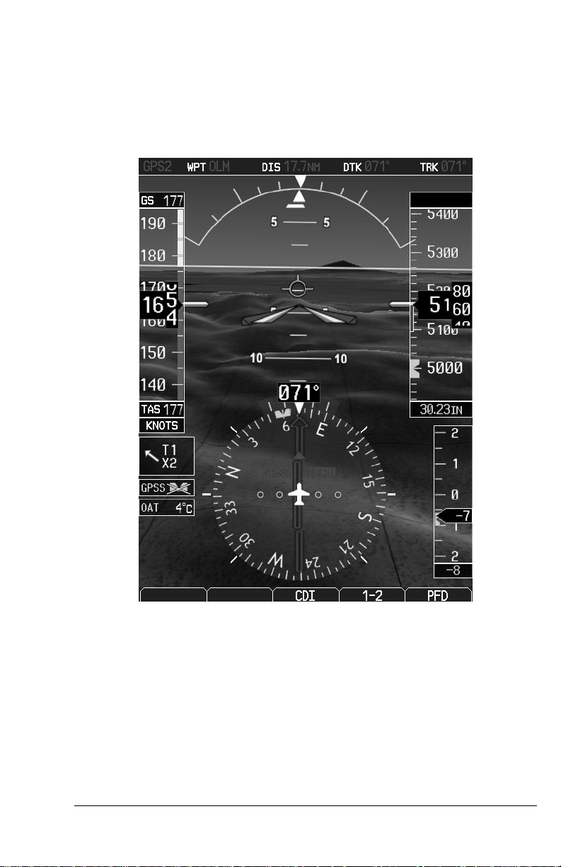
1.4 Synthetic Vision Technology
SVT uses an internal terrain database and GPS location to present the pilot with
a synthetic view of the terrain in front of the aircraft. The purpose of the SVT
system is to assist the pilot in maintaining situational awareness with regard to
the terrain and traffic surrounding the aircraft. A typical SVT display is shown
below:
SVT provides additional features on the G600 primary flight display (PFD)
which display the following information:
Synthetic Terrain; an artificial, database derived, three dimensional
view of the terrain ahead of the aircraft within a field of view of
approximately 25 degrees left and 25 degrees right of the aircraft
heading.
Obstacles; obstacles such as towers, including buildings over 200 AGL
that are within the depicted synthetic terrain field of view.
AFMS, GARMIN G600 PFD/MFD SYSTEM 190-00601-01 Rev. J
FAA APPROVED Page 13 of 46

Flight Path Marker (FPM); an indication of the current lateral and
vertical path of the aircraft. The FPM is always displayed when
synthetic terrain is selected for display.
Traffic; a display on the PFD indicating the position of other aircraft
detected by a traffic system interfaced to the G600 system.
Horizon Line; a white line indicating the true horizon is always
displayed on the SVT display.
Horizon Heading; a pilot selectable display of heading marks
displayed just above the horizon line on the PFD.
Airport Signs; pilot selectable “signposts” displayed on the synthetic
terrain display indicating the position of nearby airports that are in the
G600 database.
Runway Highlight; a highlighted presentation of the location and
orientation of the runway(s) at the destination airport.
The synthetic terrain depiction displays an area approximating the view from the
pilot’s eye position when looking directly ahead out the windshield in front of
the pilot. Terrain features outside this field of view are not shown on the display.
The synthetic terrain display is intended to aid the pilot awareness of the terrain
and obstacles in front of the airplane. It may not provide either the accuracy or
fidelity, or both, on which to solely base decisions and plan maneuvers to avoid
terrain or obstacles. The synthetic vision elements are not intended to be used for
primary aircraft control in place of the primary flight instruments.
1.5 Autopilot Interface
The G600 may be interfaced to an optional autopilot. The G600 typically
provides course and heading datum to the autopilot based on the data selected
for display on the HSI. For multiple GPS/NAV systems, the G600 acts as a
selection hub for the autopilot’s NAV mode, and the G600 may also provide
GPS Steering data. Some autopilots may provide Flight Director capabilities
which can be displayed on the G600 Attitude Indicator as a Single Cue Flight
Director.
1.6 Audio Panel
The G600 PFD/MFD system may be interfaced to the aircraft audio panel to
provide aural alerting generated by the G600 (required for TAWS-B
installations).
1.7 Traffic and Weather Systems
The G600 PFD/MFD system supports TIS traffic via the Garmin GTX Series
Mode-S Transponders. The system also supports TAS/TCAS/TIS traffic from
various active traffic awareness systems. The information from these systems is
available and controllable on the MFD.
AFMS, GARMIN G600 PFD/MFD SYSTEM 190-00601-01 Rev. J
FAA APPROVED Page 14 of 46
 Loading...