

Garmin G500 PILOT'S GUIDE
G500
Pilot’s
Guide

© 2009 Garmin Ltd. or its subsidiaries. All rights reserved.
This manual reflects the operation of System Software version 3.00, or later. Some differences in operation
may be observed when comparing the information in this manual to later software versions.
Garmin International, Inc., 1200 East 151st Street, Olathe, KS 66062, U.S.A.
Tel: 913/397.8200 Fax: 913/397.8282
Garmin AT, Inc., 2345 Turner Road SE, Salem, OR 97302, U.S.A.
Tel: 503/391.3411 Fax 503/364.2138
Garmin (Europe) Ltd., Liberty House, Bulls Copse Road, Hounsdown Business Park, Southampton,
SO40 9RB, U.K.
Tel. +44 (0) 870 850 1243 Fax +44 (0) 238 052 4004
Garmin Corporation, No. 68, Jangshu 2nd Road, Shijr, Taipei County, Taiwan
Tel: 886/02.2642.9199 Fax: 886/02.2642.9099
At Garmin, we value your opinion. For comments about this guide, please e-mail:
Techpubs.Salem@Garmin.com
www.garmin.com
Except as expressly provided herein, no part of this manual may be reproduced, copied, transmitted,
disseminated, downloaded or stored in any storage medium, for any purpose without the express written
permission of Garmin. Garmin hereby grants permission to download a single copy of this manual and of
any revision to this manual onto a hard drive or other electronic storage medium to be viewed for personal
use, provided that such electronic or printed copy of this manual or revision must contain the complete text
of this copyright notice and provided further that any unauthorized commercial distribution of this manual
or any revision hereto is strictly prohibited.
Garmin®, FliteCharts®, and SafeTaxi® are registered trademarks of Garmin Ltd. or its subsidiaries. Garmin
SVT™ is a trademark of Garmin Ltd. or its subsidiaries. These trademarks may not be used without the
express permission of Garmin.
NavData® is a registered trademark of Jeppesen, Inc.; SkyWatch® is a registered trademark of L-3
Communications; and XM® is a registered trademark of XM Satellite Radio, Inc.
June 2009 Printed in the U.S.A.

LIMITED WARRANTY
This Garmin product is warranted to be free from defects in materials or workmanship for two years from
the date of purchase. Within this period, Garmin will, at its sole option, repair or replace any components
that fail in normal use. Such repairs or replacement will be made at no charge to the customer for parts
and labor, provided that the customer shall be responsible for any transportation cost. This warranty does
not cover failures due to abuse, misuse, accident, or unauthorized alterations or repairs.
Foreward
System
Sec 1
THE WARRANTIES AND REMEDIES CONTAINED HEREIN ARE EXCLUSIVE AND IN LIEU OF ALL OTHER
WARRANTIES EXPRESS OR IMPLIED OR STATUTORY, INCLUDING ANY LIABILITY ARISING UNDER
ANY WARRANTY OF MERCHANTABILITY OR FITNESS FOR A PARTICULAR PURPOSE, STATUTORY OR
OTHERWISE. THIS WARRANTY GIVES YOU SPECIFIC LEGAL RIGHTS, WHICH MAY VARY FROM STATE TO
STATE.
IN NO EVENT SHALL GARMIN BE LIABLE FOR ANY INCIDENTAL, SPECIAL, INDIRECT OR CONSEQUENTIAL
DAMAGES, WHETHER RESULTING FROM THE USE, MISUSE, OR INABILITY TO USE THIS PRODUCT OR
FROM DEFECTS IN THE PRODUCT. Some states do not allow the exclusion of incidental or consequential
damages, so the above limitations may not apply to you.
Garmin retains the exclusive right to repair or replace the unit or software, or to offer a full refund of the
purchase price, at its sole discretion. SUCH REMEDY SHALL BE YOUR SOLE AND EXCLUSIVE REMEDY FOR
ANY BREACH OF WARRANTY.
To obtain warranty service, contact your local Garmin Authorized Service Center. For assistance in
locating a Service Center near you, visit the Garmin web site at http://www.garmin.com or contact
Garmin Customer Service at 800-800-1020.
Sec 2
PFD
Sec 3
MFD
Avoidance
Hazard
Sec 4
Additional
Features
Sec 5
& Alerts
Annun.
Sec 6
Symbols
Sec 7
Glossary Appendix A
Sec 8
Garmin G500 Pilot’s Guide
Appendix B
Index
i190-01102-02 Rev. B

Foreword
Sec 1
System
PFD
Sec 2
MFD
Sec 3
Sec 4
Hazard
Avoidance
Sec 5
Features
Additional
WARNING: Navigation and terrain separation must NOT be predicated
upon the use of the terrain function. The G500 Terrain Proximity feature
is NOT intended to be used as a primary reference for terrain avoidance
and does not relieve the pilot from the responsibility of being aware of
surroundings during flight. The Terrain Proximity feature is only to be used
as an aid for terrain avoidance and is not certified for use in applications
requiring a certified terrain awareness system. Terrain data is obtained
from third party sources. Garmin is not able to independently verify the
accuracy of the terrain data.
WARNING: The displayed minimum safe altitudes (MSAs) are only advisory
in nature and should not be relied upon as the sole source of obstacle and
terrain avoidance information. Always refer to current aeronautical charts
for appropriate minimum clearance altitudes.
WARNING: The Garmin G500 has a very high degree of functional integrity.
However, the pilot must recognize that providing monitoring and/or selftest capability for all conceivable system failures is not practical. Although
unlikely, it may be possible for erroneous operation to occur without a fault
indication shown by the G500. It is thus the responsibility of the pilot to
detect such an occurrence by means of cross-checking with all redundant
or correlated information available in the cockpit.
Sec 6
Annun.
Sec 7
Sec 8
Appendix B
& Alerts
Symbols
GlossaryAppendix A
Index
ii
WARNING: The altitude calculated by GPS receivers is geometric height
above Mean Sea Level and could vary significantly from the altitude
displayed by pressure altimeters, such as the output from the GDC 74A Air
Data Computer, or other altimeters in aircraft. GPS altitude should never
be used for vertical navigation. Always use pressure altitude displayed by
the G500 PFD or other pressure altimeters in aircraft.
WARNING: Do not use outdated database information. Databases used
in the G500 system must be updated regularly in order to ensure that the
information remains current. Pilots using an outdated database do so
entirely at their own risk.
WARNING: Do not use basemap (land and water data) information for
primary navigation. Basemap data is intended only to supplement other
approved navigation data sources and should be considered as an aid to
enhance situational awareness.
Garmin G500 Pilot’s Guide
190-01102-02 Rev. B

WARNING: Traffic information shown on the G500 Multi Function Display
is provided as an aid in visually acquiring traffic. Pilots must maneuver
the aircraft based only upon ATC guidance or positive visual acquisition
of conflicting traffic.
WARNING: XM Weather should not be used for hazardous weather
penetration. Weather information provided by the GDL 69/69A is approved
only for weather avoidance, not penetration.
WARNING: NEXRAD weather data is to be used for long-range planning
purposes only. Due to inherent delays in data transmission and the relative
age of the data, NEXRAD weather data should not be used for short-range
weather avoidance.
WARNING: For safety reasons, G500 operational procedures must be
learned on the ground.
WARNING: To reduce the risk of unsafe operation, carefully review and
understand all aspects of the G500 Pilot’s Guide. Thoroughly practice
basic operation prior to actual use. During flight operations, carefully
compare indications from the G500 to all available navigation sources,
including the information from other NAVAIDs, visual sightings, charts, etc.
For safety purposes, always resolve any discrepancies before continuing
navigation.
Foreward
System
Sec 1
Sec 2
PFD
Sec 3
MFD
Avoidance
Hazard
Sec 4
Additional
Features
Sec 5
& Alerts
Annun.
Sec 6
WARNING: Never use the G500 to attempt to penetrate a thunderstorm.
Both the FAA Advisory Circular, Subject: Thunderstorms, and the Airman’s
Information Manual (AIM) recommend avoiding “by at least 20 miles any
thunderstorm identified as severe or giving an intense radar echo.”
WARNING: Exceeding 200 deg/second in pitch or roll may invalidate
AHRS attitude provided to the G500. Exceeding 450 KIAS may invalidate
ADC information provided to the G500.
WARNING: Because of anomalies in the earth’s magnetic field, operating
the G500 within the following areas could result in loss of reliable attitude
and heading indications. North of 70° North latitude and south of 70°
South latitude. An area north of 65° North latitude and between longitude
75° West and 120° West. An area south of 55° South latitude between
longitude 120° East and 165° East.
Garmin G500 Pilot’s Guide
Symbols
Sec 7
Glossary Appendix A
Sec 8
Appendix B
Index
iii190-01102-02 Rev. B
Foreword
Sec 1
System
PFD
Sec 2
MFD
Sec 3
Sec 4
Hazard
Avoidance
Sec 5
Features
Additional
WARNING: Do not use Terrain-SVT information for primary terrain
avoidance. Terrain-SVT is intended only to enhance situational
awareness.
CAUTION: The United States government operates the Global Positioning
System and is solely responsible for its accuracy and maintenance. The
GPS system is subject to changes which could affect the accuracy and
performance of all GPS equipment. Portions of the Garmin G500 utilize
GPS as a precision electronic NAVigation AID (NAVAID). Therefore, as
with all NAVAIDs, information presented by the G500 can be misused or
misinterpreted and, therefore, become unsafe.
CAUTION: The Garmin G500 does not contain any user-serviceable parts.
Repairs should only be made by an authorized Garmin service center.
Unauthorized repairs or modifications could void both the warranty and
the pilot’s authority to operate this device under FAA/FCC regulations.
CAUTION: The G500 PFD and MFD displays use a lens coated with a
special anti-reflective coating that is very sensitive to skin oils, waxes, and
abrasive cleaners. CLEANERS CONTAINING AMMONIA WILL HARM THE
ANTI-REFLECTIVE COATING. It is very important to clean the lens using a
clean, lint-free cloth and an eyeglass lens cleaner that is specified as safe
for anti-reflective coatings.
Sec 6
Annun.
Sec 7
Sec 8
Appendix B
& Alerts
Symbols
GlossaryAppendix A
Index
iv
NOTE: Interference from GPS repeaters operating inside nearby hangars
can cause an intermittent loss of attitude and heading displays while the
aircraft is on the ground. Moving the aircraft more than 100 feet away
from the source of the interference should alleviate the condition.
NOTE: All visual depictions contained within this document, including
screen images of the G500 bezel and displays, are subject to change and
may not reflect the most current GDU 620 system. Depictions of equipment
may differ slightly from the actual equipment.
NOTE: This device complies with part 15 of the FCC Rules. Operation is
subject to the following two conditions: (1) this device may not cause
harmful interference, and (2) this device must accept any interference
received, including interference that may cause undesired operation.
NOTE: Terrain data is not displayed when the aircraft latitude is greater
than 75° North or 60° South.
Garmin G500 Pilot’s Guide
190-01102-02 Rev. B

NOTE: This product, its packaging, and its components contain chemicals
known to the State of California to cause cancer, birth defects, or
reproductive harm. This notice is being provided in accordance with
California’s Proposition 65. If you have any questions or would like
additional information, please refer to our web site at www.garmin.com/
prop65.
NOTE: Terrain-SVT is standard when the Garmin Synthetic Vision
Technology™ (SVT) option is installed.
Foreward
System
Sec 1
Sec 2
PFD
Sec 3
MFD
Avoidance
Hazard
Sec 4
Additional
Features
Sec 5
& Alerts
Annun.
Sec 6
Garmin G500 Pilot’s Guide
Symbols
Sec 7
Glossary Appendix A
Sec 8
Appendix B
Index
v190-01102-02 Rev. B
Foreword
Sec 1
System
PFD
Sec 2
MFD
Sec 3
Sec 4
Hazard
Avoidance
Sec 5
Features
Additional
Record of Revisions
Part Number Revision Date Description
190-01102-02 A
B
6/1/09
6/17/09
Production release
Formatting changes
Sec 6
Annun.
Sec 7
Sec 8
Appendix B
& Alerts
Symbols
GlossaryAppendix A
Index
vi
Garmin G500 Pilot’s Guide
190-01102-02 Rev. B

Contents
1 System Overview .................................................................................1-1
1.1 System Description ................................................................................ 1-1
1.1.1 Line Replaceable Units (LRU) .................................................1-2
1.1.2 GDU 620 .............................................................................. 1-3
1.1.3 GDC 74A ..............................................................................1-3
1.1.4 GRS 77 .................................................................................1-4
1.1.5 GMU 44 ................................................................................1-4
1.1.6 GTX 330/330D (Optional) ......................................................1-5
1.1.7 GTP 59 ................................................................................. 1-5
1.1.8 GDL 69/69A (Optional) ..........................................................1-6
1.1.9 GAD 43 (Optional) ................................................................1-6
1.1.10 GWX 68 Weather Radar ........................................................ 1-7
1.1.11 Garmin Navigator Interface .................................................... 1-7
1.1.12 Attitude Heading Reference System (AHRS) ............................1-7
1.1.13 Secure Data Cards ................................................................. 1-8
1.1.14 Pilot Controls ........................................................................1-9
1.1.14.1 PFD Knob ..............................................................................1-9
1.1.14.2 PFD Bezel Keys ....................................................................1-10
1.1.14.3 PFD Soft Keys ......................................................................1-11
1.1.14.4 MFD Knobs .........................................................................1-13
1.1.14.5 MFD Bezel Keys ................................................................... 1-13
1.1.14.6 MFD Soft Keys ..................................................................... 1-14
1.2 System Power Up ................................................................................1-15
1.2.1 Autopilot Test ...................................................................... 1-16
1.2.2 International Geomagnetic Reference Field ..........................1-17
1.3 System Operation ................................................................................ 1-17
1.3.1 Using the Page Menus ......................................................... 1-17
1.3.1.1 Navigating within a Menu ................................................... 1-18
1.3.2 Using the Soft Key Controls .................................................1-18
1.3.3 System Settings ................................................................... 1-19
1.3.4 Display Backlighting ............................................................1-21
1.3.5 Dual GDU 620 Installations .................................................1-22
1.3.5.1 Crossfill Information ............................................................ 1-22
1.3.5.2 Crossfill Selection ................................................................ 1-23
Foreward
System
Sec 1
Sec 2
PFD
Sec 3
MFD
Avoidance
Hazard
Sec 4
Additional
Features
Sec 5
& Alerts
Annun.
Sec 6
Symbols
Sec 7
Glossary Appendix A
Sec 8
Appendix B
Index
Garmin G500 Pilot’s Guide
vii190-01102-02 Rev. B

2 Primary Flight Display (PFD) ................................................................2-1
2.1 PFD Soft Key Map ................................................................................. 2-2
2.2 Airspeed Indicator ................................................................................. 2-2
Foreword
2.2.1 Markings ............................................................................... 2-3
2.2.2 Reference Speeds ..................................................................2-5
2.3 Attitude Indicator .................................................................................. 2-5
Sec 1
System
2.3.1 Extreme Attitude ...................................................................2-7
2.4 Altimeter ..............................................................................................2-9
2.4.1 Setting the Altitude Bug and Alerter ....................................... 2-9
PFD
Sec 2
Sec 3
Sec 4
Hazard
Sec 5
Additional
Sec 6
Annun.
Sec 7
Sec 8
Appendix B
2.4.2 Altitude Alerting ..................................................................2-10
2.4.3 Changing Barometric Setting ...............................................2-10
2.4.4 Minimum Descent Altitude/Decision Height Alerting .............2-11
MFD
2.5 Vertical Speed (V/S) Indicator ..............................................................2-13
2.6 Horizontal Situational Indicator ...........................................................2-14
2.6.1 Setting the Heading Bug ......................................................2-15
2.6.2 Turn Rate Indicator ..............................................................2-16
Avoidance
2.7 Course Deviation Indicator .................................................................. 2-16
2.7.1 Changing CDI Sources ......................................................... 2-17
2.7.2 Changing CDI Course ..........................................................2-18
Features
2.7.3 Vertical Deviation Indicator (VDI) .........................................2-19
2.7.4 Auto-Slewing ......................................................................2-20
2.8 Supplemental Flight Data .................................................................... 2-22
2.8.1 Bearing Pointers .................................................................. 2-22
& Alerts
2.8.2 Temperature Display ............................................................2-24
2.9 Wind Vectors ....................................................................... 2-24
3 Multi-Function Display (MFD) ..............................................................3-1
Symbols
3.1 Functional Display Map .........................................................................3-2
3.2 MFD Soft Key Map ................................................................................3-3
3.3 Navigation Map Pages ..........................................................................3-4
GlossaryAppendix A
3.3.1 Default Navigation Map Page ................................................ 3-5
3.3.2 Editing Information ................................................................ 3-5
3.3.3 Selecting Page Options ..........................................................3-5
3.3.4 Changing the Navigation Map Range ....................................3-5
3.3.5 Decluttering Map Pages ......................................................... 3-6
3.3.7 Selecting Items on the Map ...................................................3-9
Index
3.3.8 Measuring Distances ...........................................................3-10
3.3.9 Customizing Navigation Map Pages .....................................3-11
viii
Garmin G500 Pilot’s Guide
190-01102-02 Rev. B

3.3.10 Map Setup ..........................................................................3-11
3.3.10.1 Map Feature Options ........................................................... 3-13
3.3.10.2 Weather Feature Options (Optional) ..................................... 3-27
3.3.10.3 Traffic Feature Options (Optional) ......................................... 3-30
3.3.10.4 Aviation Feature Options ..................................................... 3-31
3.4 Aux Mode Pages ................................................................................. 3-42
3.4.1 System Settings ................................................................... 3-42
3.4.1.1 Display Brightness ............................................................... 3-43
3.4.1.2 Airspeed Reference Marks ................................................... 3-44
3.4.1.3 PFD Options - Wind Vector ...................................................3-45
3.4.1.4 Synchronization (Dual Installations Only) .............................. 3-46
3.4.1.5 Date and Time ..................................................................... 3-47
3.4.1.6 MFD Display Units ...............................................................3-48
3.4.1.7 System Display Units ...........................................................3-49
3.4.2 XM Information (Optional) ...................................................3-50
3.4.3 XM Entertainment Radio (Optional) .....................................3-51
3.4.4 System Status ......................................................................3-52
3.5 Flight Plan Pages ................................................................................ 3-53
3.5.1 Active Flight Plan Page ........................................................ 3-53
3.5.1.1 Active Flight Plan Detail .......................................................3-54
3.5.1.2 Active Flight Plan Options ....................................................3-54
3.5.1.3 Setting the Altitude Minimums Alerter .................................. 3-55
3.5.2 Waypoint Information Page .................................................3-56
3.5.2.1 Selecting a Waypoint ...........................................................3-56
3.5.2.2 Waypoint Information Detail ................................................3-57
3.5.2.3 Waypoint Weather Information (Optional) ............................ 3-59
3.5.3 Charts Page (Optional) ........................................................3-61
3.5.3.1 Viewing Charts ....................................................................3-62
3.5.3.2 Selecting a New Chart by Airport .........................................3-63
3.5.3.3 Selecting a New Chart by FPL, NRST, or RECENT ...................3-64
3.5.3.4 Change Day/Night View .......................................................3-64
4 Hazard Avoidance ................................................................................4-1
4.1 Terrain Configurations ........................................................................... 4-1
4.2 Terrain Proximity ................................................................................... 4-3
4.2.1 Displaying Terrain Proximity ...................................................4-4
4.2.1.1 Terrain Proximity Page 120° Arc or 360° Rings .......................4-5
4.2.1.2 Terrain Proximity Page Aviation Data ......................................4-6
Foreward
System
Sec 1
Sec 2
PFD
Sec 3
MFD
Avoidance
Hazard
Sec 4
Additional
Features
Sec 5
& Alerts
Annun.
Sec 6
Symbols
Sec 7
Glossary Appendix A
Sec 8
Appendix B
Index
Garmin G500 Pilot’s Guide
ix190-01102-02 Rev. B

4.2.2 Terrain Proximity Limitations ..................................................4-8
4.2.3 System Status ........................................................................4-8
4.3 External TAWS ......................................................................................4-9
Foreword
4.4 Garmin Terrain-SVT™ (Optional) .........................................................4-10
4.4.1.1 Garmin Terrain-SVT™ Page 120° Arc or 360° Rings .............4-11
4.4.1.2 Garmin Terrain-SVT™ Page Aviation Data ............................4-12
Sec 1
System
4.4.1.3 Inhibiting/Enabling Garmin Terrain-SVT™ Alerting ...............4-12
4.4.1.4 Synthetic Vision Alerts and Annunciations .............................4-13
4.5 TAS Traffic (Optional) ...........................................................................4-15
PFD
Sec 2
4.5.1 Displaying and Operating Traffic (TAS Systems) ..................... 4-15
4.5.1.1 Switching from Standby Mode to Operating Mode ............... 4-15
4.5.1.2 Range Ring ......................................................................... 4-16
4.5.2 Altitude Display ................................................................... 4-17
MFD
Sec 3
4.5.3 TAS Symbology .................................................................... 4-18
4.5.4 Traffic System Status ............................................................4-19
Sec 4
Hazard
4.5.5 Traffic Pop-Up......................................................................4-21
Avoidance
4.6 TIS Traffic (Optional) ............................................................................4-22
4.6.1 Traffic Map Page..................................................................4-22
4.6.2 TIS Symbology ..................................................................... 4-24
Sec 5
Features
Additional
4.6.3 TIS Limitations ..................................................................... 4-25
4.6.4 TIS Alerts ............................................................................. 4-27
4.6.5 Traffic Pop-Up......................................................................4-28
Sec 6
Annun.
4.6.6 TIS System Status ................................................................4-28
& Alerts
4.7 XM Weather (Optional) .......................................................................4-31
4.7.1 Using XM Satellite Weather Products ................................... 4-31
Sec 7
4.7.2 Customizing the XM Weather Map ......................................4-31
Symbols
4.7.3 XM Weather Symbols and Product Age ................................ 4-34
4.7.4 Weather Legends ................................................................4-36
Sec 8
4.7.5 NEXRAD ............................................................................. 4-37
GlossaryAppendix A
4.7.5.1 Reflectivity ..........................................................................4-38
4.7.5.2 NEXRAD Limitations ............................................................4-39
4.7.6 Weather Page Map Orientation ............................................4-40
4.7.7 NEXRAD Data Viewing Range .............................................. 4-40
4.7.8 NEXRAD Legend.................................................................. 4-41
4.7.9 Echo Tops ............................................................................ 4-42
Appendix B
4.7.11 XM Lightning ......................................................................4-46
4.7.10 Cloud Tops .......................................................................... 4-44
Index
4.7.12 Cell Movement ....................................................................4-47
x
Garmin G500 Pilot’s Guide
190-01102-02 Rev. B

4.7.13 SIGMETs and AIRMETs ........................................................4-49
4.7.14 METARs .............................................................................. 4-51
4.7.15 Surface Analysis and City Forecast ........................................ 4-53
4.7.16 Freezing Level......................................................................4-56
4.7.17 Winds Aloft ......................................................................... 4-58
4.7.18 County Warnings ................................................................. 4-61
4.8 GWX Weather Radar (Optional) ........................................................... 4-63
4.8.1 Garmin GWX 68 Radar Description ...................................... 4-63
4.8.1.1 Principles of Pulsed Airborne Weather Radar ........................ 4-63
4.8.1.2 Antenna Beam Illumination ................................................. 4-64
4.8.1.3 Radar Signal Attenuation ..................................................... 4-65
4.8.2 Radar Signal Reflectivity ......................................................4-66
4.8.2.1 Precipitation ........................................................................ 4-66
4.8.2.2 Ground Returns ................................................................... 4-67
4.8.2.3 Angle of Incidence ...............................................................4-67
4.8.3 Operating Distance ..............................................................4-68
4.8.4 Basic Antenna Tilt Setup ......................................................4-69
4.8.5 Weather Mapping and Interpretation ................................... 4-70
4.8.5.1 Weather display Interpretation .............................................4-70
4.8.5.2 Thunderstorms ....................................................................4-71
4.8.5.3 Tornadoes ........................................................................... 4-73
4.8.5.4 Hail ..................................................................................... 4-73
4.8.6 Radar Operation in Weather Mode ....................................... 4-74
4.8.6.1 Displaying Weather on the Weather Radar Page ................... 4-75
4.8.6.2 Vertically Scanning a Storm Cell ...........................................4-76
4.8.6.3 Adjusting the Antenna Tilt Angle .......................................... 4-77
4.8.6.4 Adjusting Gain .................................................................... 4-78
4.8.6.5 Sector Scan ......................................................................... 4-80
4.8.6.6 Antenna Stabilization .......................................................... 4-81
4.8.6.7 Weather Attenuated Color Highlight (WATCH™) ................. 4-81
4.8.6.8 Weather Alert ......................................................................4-82
4.8.7 Ground Mapping and Interpretation ....................................4-83
5 Additional Features (Optional) ............................................................5-1
5.1 Viewing Charts .....................................................................................5-2
5.1.1 Chart Panning ....................................................................... 5-3
5.1.2 Choosing a Chart for the Current Airport ................................5-4
5.1.3 Selecting a Chart by Identifier ................................................ 5-5
Foreward
System
Sec 1
Sec 2
PFD
Sec 3
MFD
Avoidance
Hazard
Sec 4
Additional
Features
Sec 5
& Alerts
Annun.
Sec 6
Symbols
Sec 7
Glossary Appendix A
Sec 8
Appendix B
Index
Garmin G500 Pilot’s Guide
xi190-01102-02 Rev. B

5.1.4 Selecting a New Chart by FPL, NRST, or RECENT .....................5-6
5.1.5 Viewing Chart NOTAMs .........................................................5-7
5.1.6 Day/Night View ..................................................................... 5-7
Foreword
5.2 ChartView ............................................................................................5-8
5.2.1 Cycle Number and Revision ...................................................5-8
®
5.3 FliteCharts
Sec 1
System
5.3.1 Cycle Number and Revision .................................................5-11
5.4 SafeTaxi
5.4.1 Using SafeTaxi
PFD
Sec 2
....................................................................................... 5-11
®
..........................................................................................5-13
®
.................................................................5-14
5.4.1.1 Decluttering ........................................................................ 5-14
5.4.1.2 Hot Spot Information ........................................................... 5-14
®
Cycle Number and Revision .................................. 5-15
®
Satellite Radio Services ................................ 5-17
®
Information .................................................................5-19
®
Entertainment Radio ...................................................5-20
Sec 4
MFD
Sec 3
Hazard
Avoidance
5.4.2 SafeTaxi
5.5 XM
®
Radio Entertainment ..................................................................5-17
5.5.1 Activating XM
5.5.2 XM
5.5.3 XM
5.5.3.1 Channel Categories .............................................................5-21
®
Radio Channel ......................................... 5-22
Sec 5
Features
Additional
5.5.3.2 Selecting an XM
®
5.5.3.3 XM
5.5.3.4 XM
Radio Volume ..............................................................5-23
®
Radio Channel Presets ................................................. 5-24
5.5.4 GDL 69/69A Data Link Receiver Troubleshooting .................. 5-25
5.6 Autopilot Operation ............................................................................ 5-26
Sec 6
Annun.
& Alerts
5.6.1 Heading .............................................................................. 5-26
5.6.2 Altitude Capture (Optional Interface) ...................................5-26
Sec 7
5.6.3 Autopilot Navigation ...........................................................5-27
Symbols
5.6.3.1 Autopilot Operation with GPSS Enabled Autopilots ............... 5-27
5.6.3.2 Autopilot Operation with the GDU 620 Emulating GPSS ....... 5-28
5.7 Garmin Synthetic Vision Technology (SVT™) (Optional) ........................5-30
Sec 8
5.7.1 Garmin SVT™ Operation ..................................................... 5-32
GlossaryAppendix A
5.7.2 Activating and Deactivating Garmin SVT™ .......................... 5-33
5.7.3 Garmin SVT™ Features ....................................................... 5-34
5.7.3.1 Flight Path Marker (FPM) .....................................................5-34
5.7.3.2 Zero-Pitch Line .................................................................... 5-34
5.7.2.3 Horizon Heading .................................................................5-35
5.7.2.4 Airport Signs ....................................................................... 5-35
Index
Appendix B
5.7.2.5 Runway Depiction ............................................................... 5-36
5.7.2.6 Traffic .................................................................................. 5-37
xii
Garmin G500 Pilot’s Guide
190-01102-02 Rev. B

5.7.2.7 Obstacles ............................................................................ 5-38
5.7.2.8 Field of View .......................................................................5-39
5.7.2.9 Unusual Attitudes ................................................................ 5-41
6 Annunciations and Alerts .....................................................................6-1
6.1 Alerts ...................................................................................................6-1
6.2 System Status .......................................................................................6-8
7 Symbols ................................................................................................7-1
7.1 Map Page Symbols ................................................................................7-1
7.2 SafeTaxi
™ Symbols ............................................................................. 7-2
7.3 Traffic Symbols ......................................................................................7-2
7.4 Terrain Obstacle Symbols ....................................................................... 7-3
7.5 Basemap Symbols ................................................................................. 7-4
7.6 Map Tool Bar Symbols ........................................................................... 7-4
7.7 XM Weather Tool Bar Symbols ............................................................... 7-5
7.8 Miscellaneous Symbols .......................................................................... 7-6
8 Glossary ...............................................................................................8-1
Foreward
System
Sec 1
Sec 2
PFD
Sec 3
MFD
Avoidance
Hazard
Sec 4
Appendix A ................................................................................................. A-1
SD Card Use and Databases ..........................................................................A-1
Jeppesen Databases ...............................................................................A-1
Updating the Jeppesen navigation database ...........................................A-1
Garmin Databases ..................................................................................A-2
Updating Garmin databases ...................................................................A-3
Index ........................................................................................................... B-1
Additional
Features
Sec 5
& Alerts
Annun.
Sec 6
Symbols
Sec 7
Glossary Appendix A
Sec 8
Appendix B
Index
Garmin G500 Pilot’s Guide
xiii190-01102-02 Rev. B

Foreword
Sec 1
System
PFD
Sec 2
MFD
Sec 3
Sec 4
Hazard
Avoidance
Sec 5
Features
Additional
Sec 6
Annun.
& Alerts
This page intentionally left blank
Sec 7
Symbols
Sec 8
GlossaryAppendix A
Index
Appendix B
xiv
Garmin G500 Pilot’s Guide
190-01102-02 Rev. B
1 SYSTEM OVERVIEW
1.1 System Description
Foreword
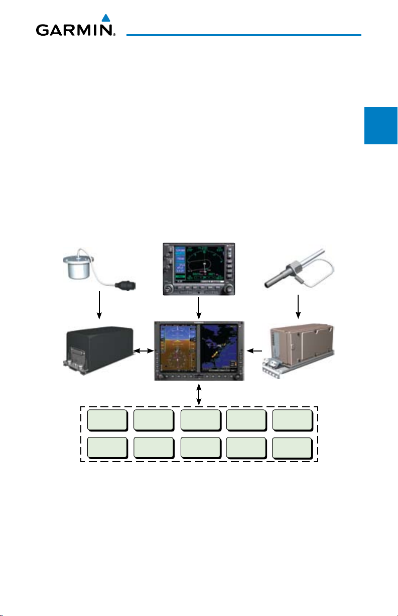
This section provides an overview of the G500 Avionics Display System.
The G500 system is an integrated display system that presents primary flight
System
instrumentation, navigation, and a moving map to the pilot through largeformat displays.
In normal operating mode, the Primary Flight Display (PFD) presents
PFD
graphical flight instrumentation (attitude, heading, airspeed, altitude, vertical
speed), replacing the traditional flight instrument cluster. The Multi-Function
Display (MFD) normally displays a full-color moving map with navigation
MFD
information.
GMU 44 Magnetometer
GRS 77 AHRS
Audio Panel
SL 30
GPS Navigator(s)
GDU 620
Optional Interfaces
Autopilot
Flight Director
ADF
GDL 69/69A
Traffic
Skywatch
GWX 68
Temperature Probe
GDC 74 Air Data Computer
GTX330/330D
GAD 43
Avoidance
Features
& Alerts
Symbols
Glossary Appendix A
Sec 1
Sec 2
Sec 3
Hazard
Sec 4
Additional
Sec 5
Annun.
Sec 6
Sec 7
Sec 8
Figure 1-1 G500 System (LRU Configuration)
The system consists of the following Line Replaceable Units (LRUs):
• GDU 620 Primary Flight Display (PFD) and Multi Function Display
(MFD)
• GDC 74A Air Data Computer (ADC)
• GRS 77 Attitude and Heading Reference System (AHRS)
Garmin G500 Pilot’s Guide
1-1190-01102-02 Rev. B
Appendix B
Index

• GNS 480, CNX80, GNS 400W series, or GNS 500W series GPS
Navigator
• Temperature Probe (such as the GTP 59)
Foreword
• GMU 44 Magnetometer
• GTX 330/330D TIS-B Traffic (optional)
Sec 1
System
• GDL 69A Satellite Data Link Receiver (optional)
• SL30 NavCom (optional)
PFD
Sec 2
• Autopilot/Flight Director (optional)
• ADF (optional)
• Traffic (optional: TAS and TIS)
MFD
Sec 3
• Audio Panel (optional)
• GAD 43 Adapter (optional)
Sec 4
Hazard
• GWX 68 Weather Radar (optional)
Avoidance
1.1.1 Line Replaceable Units (LRU)
Sec 5
This guide covers the operation of the GDU 620 as integrated in the G500
Features
Additional
system. The G500 Avionics Display System is an advanced technology avionics
suite designed to replace the traditional flight instrument cluster. The system
combines primary flight instrumentation, navigational information, and a moving
Sec 6
Annun.
& Alerts
map all displayed on dual 6.5 inch color screens. The G500 system is composed
of sub-units or Line Replaceable Units (LRUs). LRUs have a modular design and
can be installed directly behind the instrument panel or in a separate avionics
Sec 7
Symbols
bay if desired. This design greatly eases troubleshooting and maintenance of the
G500 system. A failure or problem can be isolated to a particular LRU, which
can be replaced quickly and easily. Each LRU has a particular function, or set of
Sec 8
GlossaryAppendix A
functions, that contributes to the system’s operation.
Index
Appendix B
1-2
Garmin G500 Pilot’s Guide
190-01102-02 Rev. B
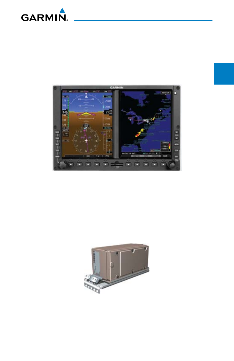
1.1.2 GDU 620
The GDU 620 has dual VGA (640 x 480 pixels) 6.5 inch LCD displays. The
left side of the GDU is a PFD and the right side is the MFD. The MFD shows
a moving map, flight plan, weather, and more. The PFD shows primary flight
information, in place of traditional pitot-static and gyroscopic systems and also
provides an HSI for navigation.
Figure 1-2 GDU 620 PFD and MFD
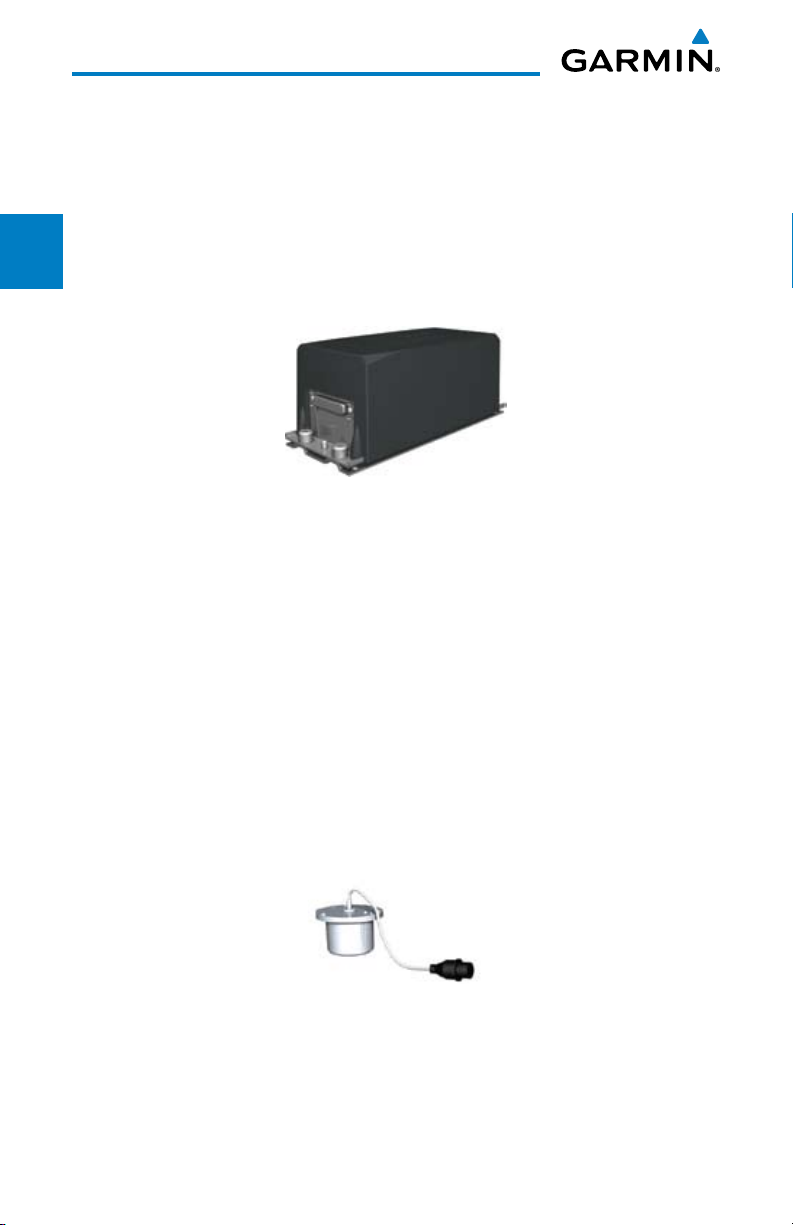
1.1.3 GDC 74A
The GDC 74A Air Data Computer (ADC) compiles information from the
pitot/static system and an Outside Air Temperature (OAT) sensor. The GDC 74A
provides pressure altitude, airspeed, vertical speed, and OAT information to the
G500 system. The GDC 74A communicates with the GDU 620 and GRS 77
using an ARINC 429 digital interface.
Foreword
System
Sec 1
Sec 2
PFD
Sec 3
MFD
Avoidance
Hazard
Sec 4
Additional
Features
Sec 5
& Alerts
Annun.
Sec 6
Symbols
Sec 7
Figure 1-3 GDC 74A Air Data Computer
Garmin G500 Pilot’s Guide
Glossary Appendix A
Index
1-3190-01102-02 Rev. B
Sec 8
Appendix B
1.1.4 GRS 77
The GRS 77 is an Attitude and Heading Reference System (AHRS) unit that
provides aircraft attitude information to the G500 display. The unit contains
Foreword
advanced tilt sensors, accelerometers, and rate sensors. In addition, the GRS 77
interfaces with both the GDC 74A Air Data Computer and the GMU 44
magnetometer. The GRS 77 also utilizes GPS data forwarded from the GDU
Sec 1
System
620. Actual attitude and heading information is sent to the GDU 620 using an
ARINC 429 digital interface.
PFD
Sec 2
MFD
Sec 3
Figure 1-4 GRS 77 AHRS
Sec 4
The IGRF (International Geomagnetic Reference Field) model is contained in
Hazard
Avoidance
the GRS 77 and is only updated once every five years. The IGRF model is part
of the Navigation Database. At system power-up, the IGRF models in the GRS
77 and in the Navigation Database are compared, and if the IGRF model in the
Sec 5
Features
Additional
GRS 77 is out of date, the user is prompted to update the IGRF model in the
GRS 77. The prompt will appear after the G500 splash screen is acknowledged
on the MFD.
Sec 6
Annun.
& Alerts
1.1.5 GMU 44
The GMU 44 magnetometer senses the earth’s magnetic field. Data is sent to
the GRS 77 AHRS for processing to determine aircraft magnetic heading. This
Sec 7
Symbols
unit receives power directly from the GRS 77 and communicates with the GRS
77 using a RS-485 digital interface.
Sec 8
GlossaryAppendix A
Figure 1-5 GMU 44 Magnetometer
Index
Appendix B
1-4
Garmin G500 Pilot’s Guide
190-01102-02 Rev. B
1.1.6 GTX 330/330D (Optional)
Foreword
Figure 1-6 GTX 330/330D Mode S Transponder
The GTX 330/330D is a solid-state transponder that provides Modes A, C,
and S functions. The transponder provides traffic information to the display
through an ARINC 429 digital interface.
NOTE: GTX 33/33D can also be used to display traffic information on the
GDU 620.
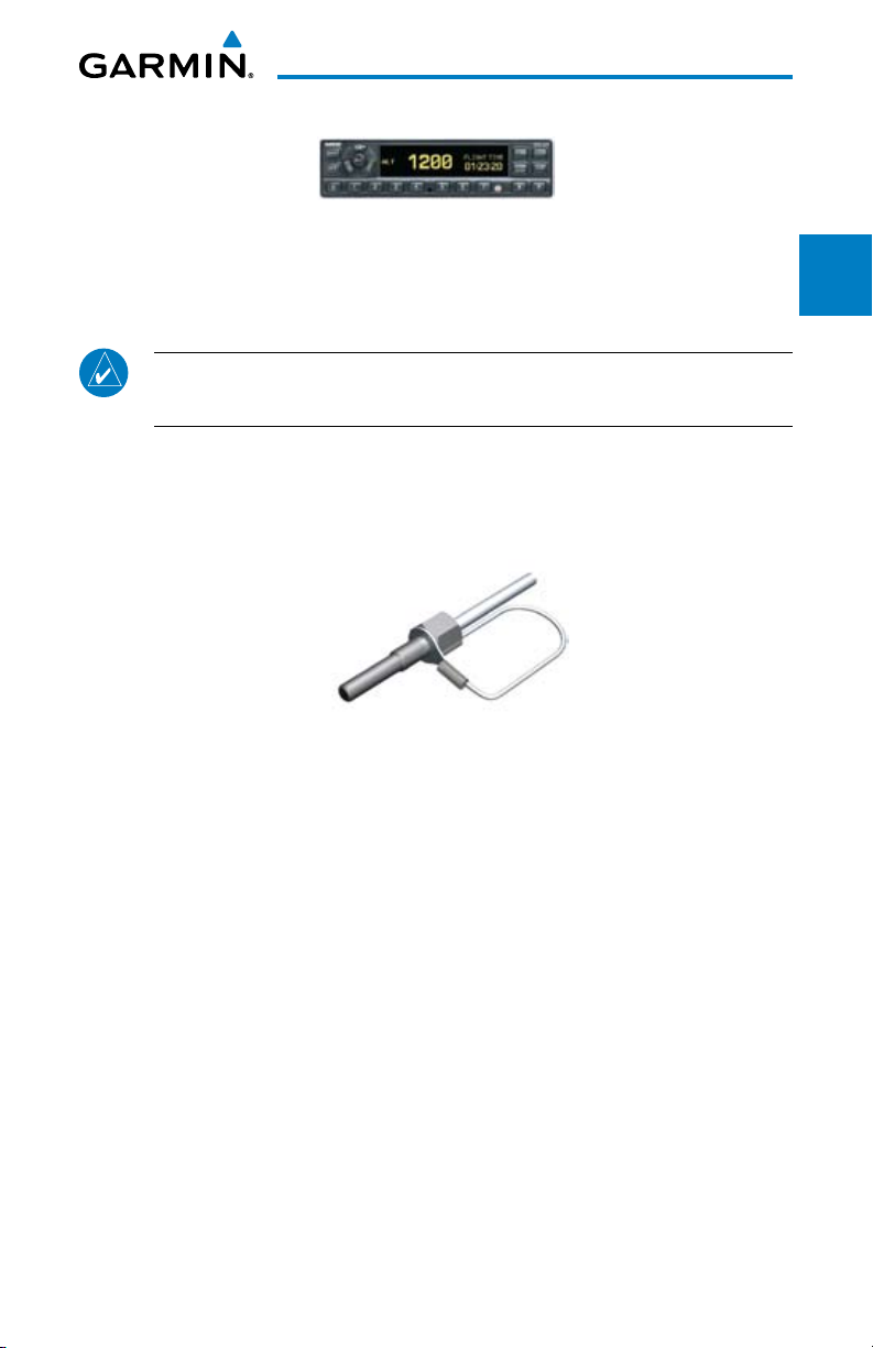
1.1.7 GTP 59
A temperature probe provides Outside Air Temperature (OAT) data to the
GDC 74A. The GTP 59 is an example of an appropriate temperature probe.
System
PFD
MFD
Avoidance
Features
Sec 1
Sec 2
Sec 3
Hazard
Sec 4
Additional
Sec 5
Figure 1-7 GTP 59 Temperature Probe
Garmin G500 Pilot’s Guide
& Alerts
Symbols
Glossary Appendix A
Index
1-5190-01102-02 Rev. B
Annun.
Sec 6
Sec 7
Sec 8
Appendix B
1.1.8 GDL 69/69A (Optional)
The GDL 69/69A is an XM Satellite Radio Data Link Receiver that receives
broadcast weather data. The GDL 69A is the same as the GDL 69 with the
Foreword
addition of an XM Satellite Radio audio entertainment receiver. Weather data
and control of audio channel and volume is displayed on the MFD, via a HighSpeed Data Bus (HSDB) Ethernet connection. The GDL 69A is also interfaced
Sec 1
System
to an audio panel for distribution of the audio signal. A subscription to the XM
Satellite Radio service is required to enable the GDL 69/69A capability.
PFD
Sec 2
MFD
Sec 3
Sec 4
Hazard
Avoidance
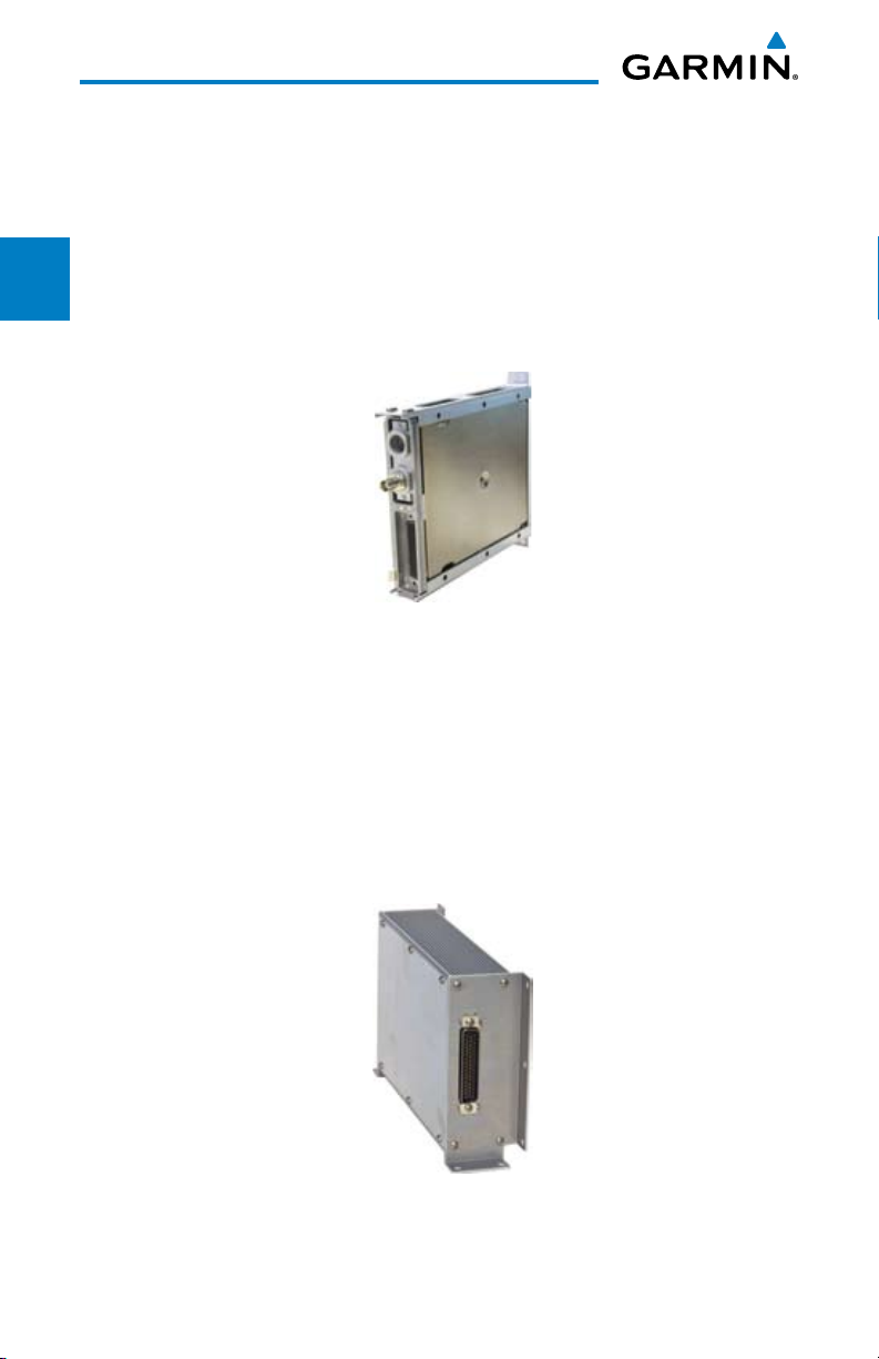
1.1.9 GAD 43 (Optional)
Sec 5
Features
Additional
The GAD 43 is an adapter that converts AHRS digital pitch, roll, heading
and yaw rate data into analog signals used by autopilot systems. The GAD 43
is installed remotely between the AHRS and an existing autopilot. The analog
Sec 6
Annun.
& Alerts
signals from the GAD 43 mimic those of spinning-mass gyros that provide
attitude data to the autopilot and allow the gyro to be replaced by the AHRS
and GAD 43 combination.
Sec 7
Symbols
Figure 1-8 GDL 69/69A XM Satellite Radio Data Link Receiver
Sec 8
GlossaryAppendix A
Index
Appendix B
1-6
Figure 1-9 GAD 43 AHRS Adapter
Garmin G500 Pilot’s Guide
190-01102-02 Rev. B
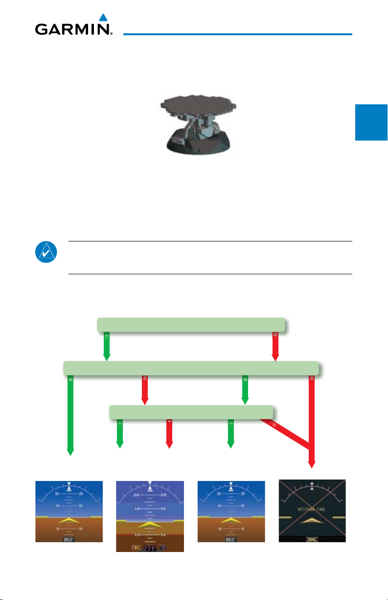
1.1.10 GWX 68 Weather Radar
Attitude/Heading Invalid
available
available
unavailable
unavailable
available
unavailable
unavailable
available
l
e
e
b
Airspeed Data
e
e
Magnetometer
unavailable
available
l
GPS
AHRS Normal
Operation
AHRS no-
Mag Mode
AHRS no-Mag/
no-Air Mode
Heading Invalid
AHRS
no-GPS
Mode
The GWX 68 provides airborne weather and ground mapped radar data to
the MFD.
Figure 1-10 GWX 68 Weather Radar
1.1.11 Garmin Navigator Interface
The G500 system requires connection to at least one external Garmin WAAS
GPS navigator, such as the 400W/500W series or GNS 480.
Foreword
System
Sec 1
Sec 2
PFD
Sec 3
MFD
1.1.12 Attitude Heading Reference System (AHRS)
NOTE: Aggressive maneuvering while AHRS is not operating in normal
mode may degrade AHRS accuracy.
Attitude and heading information is displayed on the PFD when the AHRS
receives appropriate combinations of information from the external sensor
inputs.
Avoidance
Hazard
Sec 4
Additional
Features
Sec 5
& Alerts
Annun.
Sec 6
Symbols
Sec 7
Glossary Appendix A
Sec 8
Appendix B
Index
Figure 1-11 AHRS Operation
Garmin G500 Pilot’s Guide
1-7190-01102-02 Rev. B

Loss of GPS, magnetometer, or air data inputs is communicated to the pilot by
message advisory alerts (refer to Section 6 for specific AHRS alert information).
Any failure of the internal AHRS inertial sensors results in loss of attitude and
Foreword
heading information (indicated by red “X” flags over the corresponding flight
instruments).
A maximum of two GPS inputs are provided to the AHRS. If GPS information
Sec 1
System
from one of the inputs fails, the AHRS uses the remaining GPS input and an
alert message is issued to inform the pilot. If both GPS inputs fail, the AHRS
will continue to provide attitude and heading information to the PFD as long as
PFD
Sec 2
magnetometer and airspeed data are available and valid.
If the magnetometer input fails, the AHRS continues to output valid attitude
information and GPS Track information is used; however, the heading output
MFD
Sec 3
on the PFD is flagged as invalid with a red “X,” “TRK” in magenta is annunciated
to the right of the Track value, and the Track value color is changed from white
to magenta.
Sec 4
Hazard
Avoidance
NOTE: In this case the magnetic standby compass and GPS ground track
can be used to keep the aircraft on the desired heading.
Sec 5
Failure of the air data input has no effect on the AHRS output while AHRS is
Features
Additional
receiving valid GPS information. Invalid or unavailable airspeed data in addition
to complete GPS failure results in loss of all attitude and heading information.
Sec 6
Annun.
& Alerts
1.1.13 Secure Data Cards
The G500 System uses Secure Digital (SD) cards to load and store various
types of data. For basic flight operations, SD cards are required for Terrain,
Sec 7
Symbols
Obstacle, FliteChart, SafeTaxi, and ChartView database storage as well as
Jeppesen aviation and ChartView database updates. The Navigation Database
update card is generally inserted in the upper SD card slot for database updates
Sec 8
GlossaryAppendix A
and then removed. Other database cards are normally located in the lower SD
card slot.
NOTE: Ensure the GDU 620 is powered off before inserting or removing
an SD card.
Index
Appendix B
1-8
NOTE: Refer to A-1 for instructions on updating the aviation database.
Garmin G500 Pilot’s Guide
190-01102-02 Rev. B
Inserting an SD Card
1) Insert the SD card in the SD card slot (the front of the card should be flush with
the face of the display bezel).
Foreword
2) To eject the card, gently press on the SD card to release the spring latch.
1.1.14 Pilot Controls
The GDU 620 controls have been designed to simplify operation of the
system and minimize workload and the time required to access sophisticated
functionality. Controls are located on the PFD and MFD bezels and are comprised
of a PFD knob, MFD dual concentric knobs, bezel keys, and soft keys.
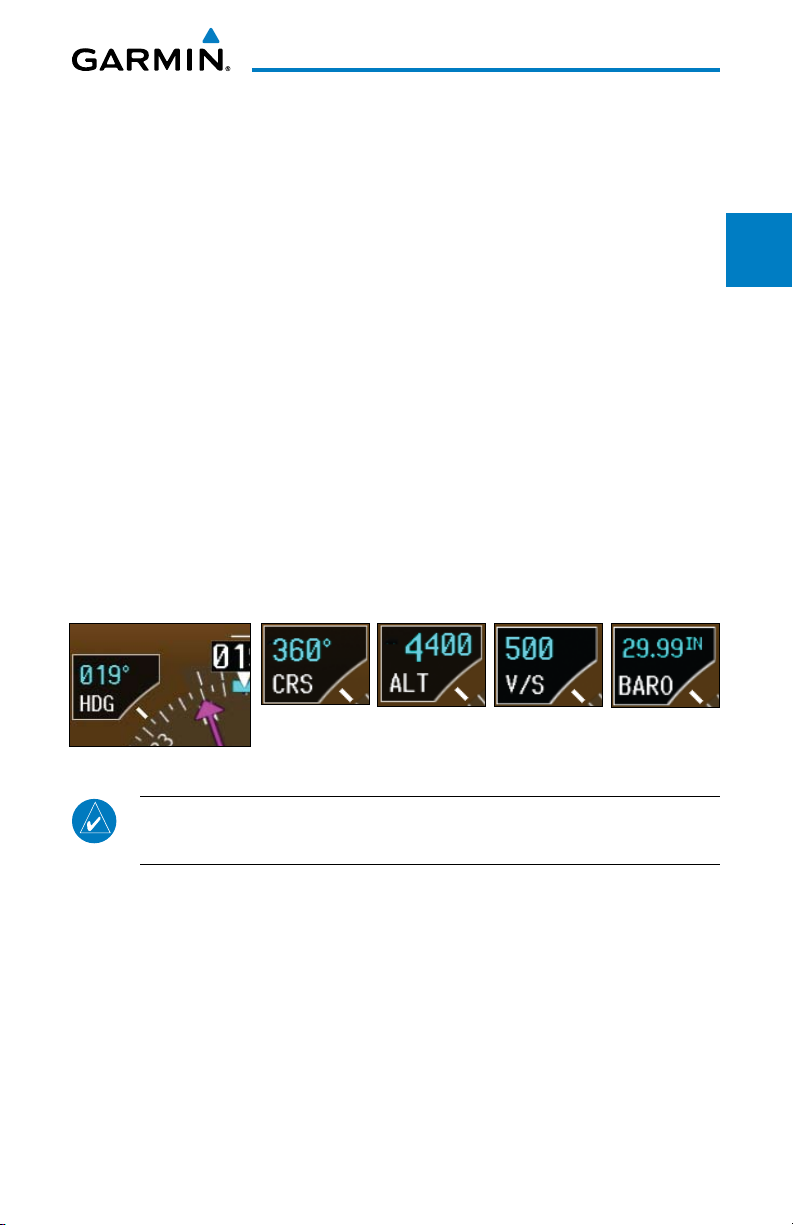
1.1.14.1 PFD Knob
Turning the PFD knob adjusts the values for the mode selected by the PFD
bezel keys, such as, Heading (HDG), Course (CRS), Altitude (ALT), Vertical
Speed (V/S), and Barometric Setting (BARO). The values are shown in a window
to the left of the HSI. Pressing the PFD knob reverts to the default value of the
selected mode.
Heading
Mode
Figure 1-12 Selection Modes Adjusted with the PFD Knob
Course
Mode
Altitude
Mode
Vertical Speed
Mode
Barometer
Mode
System
Sec 1
Sec 2
PFD
Sec 3
MFD
Avoidance
Hazard
Sec 4
Additional
Features
Sec 5
& Alerts
Annun.
Sec 6
Symbols
Sec 7
NOTE: After 10 seconds of inactivity in another mode, the PFD knob
selected mode will revert to Heading mode.
1. Press the desired PFD mode selection key (HDG, CRS, A LT, V/S, or BARO). A
window will be displayed near the upper right corner of the HSI showing the
current value for that mode.
2. Turn the PFD knob to select the desired value.
Garmin G500 Pilot’s Guide
1-9190-01102-02 Rev. B
Glossary Appendix A
Sec 8
Appendix B
Index
1.1.14.2 PFD Bezel Keys
Heading (HDG)
Selects Heading Select mode. Pressing the PFD knob in Heading mode will
Foreword
center the Heading Bug on the current Heading. This is the default mode for
the PFD knob. If the Heading is invalid, the PFD knob will revert to Course
Sec 1
mode. Set the heading on the HSI by turning the PFD knob after pressing
System
the HDG key.
Course (CRS)
PFD
Sec 2
Selects Course Select mode. Pressing the PFD knob in Course mode will
center the CDI for a VOR or OBS mode course.
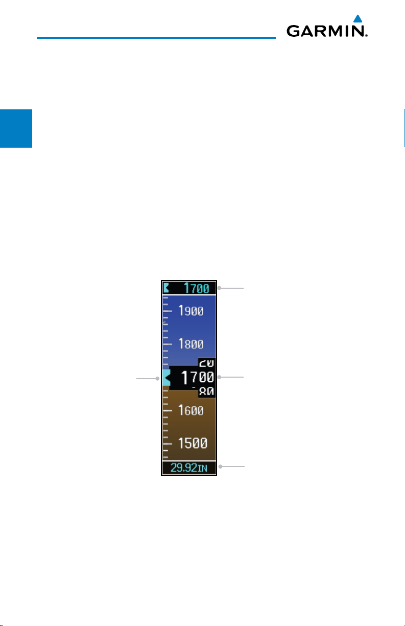
Altimeter (ALT)
MFD
Sec 3
Selects Altitude Select mode. Pressing the PFD knob in Altimeter mode will
enter the current altitude in the Altitude Select window. Set the Altitude Bug
Sec 4
Sec 5
by turning the PFD knob after pressing the ALT key.
Hazard
Avoidance
Features
Additional
Altitude Select Window
Sec 6
Annun.
Sec 7
Sec 8
Appendix B
& Alerts
Symbols
GlossaryAppendix A
Index
1-10
Altitude Bug
Current Altitude
Barometric Setting
Figure 1-13 Pressing PFD Knob Sets Altitude Select to Current Altitude
Garmin G500 Pilot’s Guide
190-01102-02 Rev. B
Vertical Speed (V/S)
Selects Vertical Speed (V/S) mode. Pressing the PFD knob in V/S mode will
synchronize the bug to the current vertical speed.
Foreword
System
Sec 1
Vertical Speed Bug
Current Vertical Speed
PFD
MFD
Avoidance
Vertical Speed Bug Setting
Figure 1-14 Pressing V/S Knob Sets Vertical Speed Bug to Current Vertical Speed
Barometer (BARO)
Features
Selects Barometric Setting Select mode. Pressing the PFD knob in Baro mode
will enter the standard pressure (29.92 in) value.
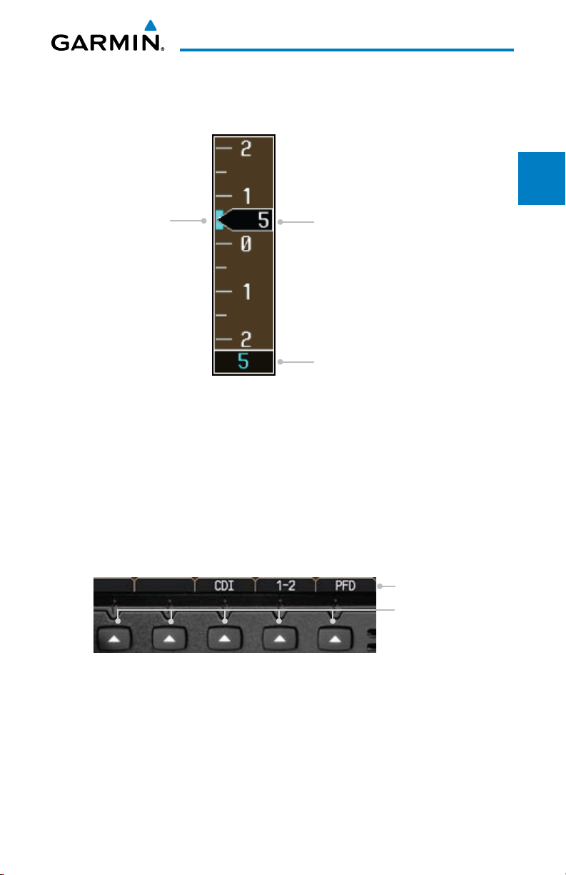
1.1.14.3 PFD Soft Keys
& Alerts
The soft keys are located along the bottoms of the displays below the soft
key labels. The soft key labels shown depend on the soft key level or page being
displayed. The soft keys can be used to select the appropriate soft key function.
Soft Key Labels
Soft Keys
Symbols
Glossary Appendix A
Sec 2
Sec 3
Hazard
Sec 4
Additional
Sec 5
Annun.
Sec 6
Sec 7
Sec 8
Figure 1-15 PFD Soft Key Layout
When a soft key is selected, its color changes to black text on gray background
and remains this way until it is turned off, at which time it reverts to white text
on black background. When a soft key function is disabled, the soft key label
is subdued (dimmed). Soft keys revert to the previous level after 45 seconds of
inactivity.
Garmin G500 Pilot’s Guide
1-11190-01102-02 Rev. B
Appendix B
Index

AP Test
The AP TEST soft key is available if the GAD 43 is installed and providing
attitude to an autopilot. The AP TEST soft key disengages the autopilot as
Foreword
part of the AHRS test.
Sec 1
System
NOTE: "AP TEST" is not available for all installations.
CDI
The CDI soft key toggles between the selection of GPS or VOR/LOC as the
PFD
Sec 2
active navigation source. In a single GDU 620 system, the GDU CDI soft
key will change the source in the connected navigator and making a source
change in the navigator will be reflected in the GDU 620. In a dual GDU 620
MFD
system, the CDI keys in the navigator will be disabled.
Sec 3
1-2
Sec 4
Hazard
Avoidance
Sec 5
Features
Additional
Sec 6
Annun.
& Alerts
Sec 7
Symbols
Sec 8
GlossaryAppendix A
Index
Appendix B
The 1-2 soft key toggles between the available receivers for selected navigation
source (i.e. GPS1 and GPS2 or VOR/LOC1 and VOR/LOC2). This soft key
will only be present if the system is configured for a second GPS or VOR/
LOC.
PFD
Pressing the PFD soft key displays the BRG1, BRG2, and BACK soft keys.
The BRG2 soft key will only be present if the system is configured for a
second GPS or VOR/LOC receiver.
BRG1
The BRG1 soft key cycles through the available bearing 1 indicator modes
(NAV1, GPS1, ADF, or None).
BRG2
The BRG2 soft key cycles through the available bearing 2 indicator modes
(NAV2, GPS2, ADF, or None). This soft key will only be present if the system
is configured for a second GPS or VOR/LOC.
SYN VIS
The SYN VIS soft key is available if Synthetic Vision Technology™ is installed.
It enables Synthetic Vision and displays the associated soft keys.
1-12
Garmin G500 Pilot’s Guide
190-01102-02 Rev. B

SYN TERR
The SYN TERR soft key is available if Synthetic Vision Technology™ is
installed and enables synthetic terrain depiction.
Foreword
HRZN HDG
The HRZN HDG soft key is available if Synthetic Vision Technology™ is
installed. Pressing this key enables horizon heading marks and digits.
APTSIGNS
The APTSIGNS soft key is available if Synthetic Vision Technology™ is
installed and enables airport sign posts.
BACK
The BACK soft key returns to the pages default soft key options.
1.1.14.4 MFD Knobs
The MFD knobs are for navigating and selecting information on the MFD
pages. More details are provided in the MFD section.
Small (Inner) MFD Knob
Selects a specific page within a page group. Pressing the small MFD knob
turns the selection cursor ON and OFF. When the cursor is ON, data may be
entered in the applicable window by turning the small and large MFD knobs.
In this case, the large MFD knob moves the cursor on the page and the small
MFD knob selects individual characters or values for the highlighted cursor
location.
Large (Outer) MFD Knob
System
Sec 1
Sec 2
PFD
Sec 3
MFD
Avoidance
Hazard
Sec 4
Additional
Features
Sec 5
& Alerts
Annun.
Sec 6
Symbols
Sec 7
Selects the MFD page group. When the cursor is ON, the large MFD knob
moves the cursor to highlight available fields.
1.1.14.5 MFD Bezel Keys
Range (RNG)
Pressing the Range arrow keys changes the range on the Map pages. The Up
arrow zooms out. The Down arrow zooms in. The keys also aid in scrolling
up and down text pages.
Garmin G500 Pilot’s Guide
1-13190-01102-02 Rev. B
Glossary Appendix A
Sec 8
Appendix B
Index

Menu
Displays a context-sensitive list of options. This list allows the user to access
additional features or make setting changes that relate to particular pages.
Foreword
Enter (ENT)
Validates or confirms a menu selection or data entry.
Sec 1
System
Clear (CLR)
Erases information, cancels entries, or removes page menus. Pressing and
holding the CLR key displays the Navigation Map 1 page.
PFD
Sec 2
1.1.14.6 MFD Soft Keys
MFD functions indicated by the soft key labels vary depending on the page
MFD
Sec 3
selected and are located at the bottom of the MFD display. Press the soft key
located directly below the soft key label. To select the function indicated on the
soft key label, press the soft key directly below the label.
Sec 4
Hazard
Avoidance
Selected Soft Key
Unselected Soft Keys
Sec 5
Features
Additional
Sec 6
Annun.
& Alerts
Sec 7
Symbols
Sec 8
GlossaryAppendix A
Index
Appendix B
1-14
Figure 1-16 MFD Soft Key Layout
Garmin G500 Pilot’s Guide
Soft Key Labels
Soft Keys
190-01102-02 Rev. B
 Loading...