

Garmin G5 Installation Manual

G5 Electronic Flight Display
Installation Manual for
Non-Certified Aircraft
190-02072-01 December, 2020 Revision 8
© 2020
Garmin Ltd. or its subsidiaries
All Rights Reserved
Except as expressly provided herein, no part of this manual may be reproduced, copied, transmitted,
disseminated, downloaded or stored in any storage medium, for any purpose without the express prior
written consent of Garmin. Garmin hereby grants permission to download a single copy of this manual and
of any revision to this manual onto a hard drive or other electronic storage medium to be viewed and to
print one copy of this manual or of any revision hereto, provided that such electronic or printed copy of this
manual or revision must contain the complete text of this copyright notice and provided further that any
unauthorized commercial distribution of this manual or any revision hereto is strictly prohibited.
Garmin International, Inc.
1200 E. 151st Street
Olathe, KS 66062 USA
Garmin (Europe) Ltd.
Liberty House, Hounsdown Business Park
Southampton, Hampshire SO40 9LR U.K.
AVIATION LIMITED WARRANTY
G5 warranty information is available at https://www.garmin.com/en-US/legal/aviation-limited-warranty.
RECORD OF REVISIONS
Revision
4 11/08/18 Updated interconnect drawings
5 07/30/19 Updated Section 7 and added GAD 13 info
6 01/28/20 Added GAD 29/29B, GMU 11, and GSA 28 info
7 05/11/20 Added Lightning Protection Module info
8 12/16/20 Added -01 Battery Pack info
Revision
Date
Description
190-02072-01 G5 Installation Manual
Rev. 8 Page A
INFORMATION SUBJECT TO EXPORT CONTROL LAWS
This document may contain information which is subject to the Export Administration Regulations
(“EAR”) issued by the United States Department of Commerce (15 CFR, Chapter VII Subchapter C) and
which may not be exported, released or disclosed to foreign nationals inside or outside the United States
without first obtaining an export license. The preceding statement is required to be included on any and all
reproductions in whole or in part of this manual.
CURRENT REVISION DESCRIPTION
Revision
8
Page
Number
iii Front Added Note regarding -01 Battery Pack SW requirement
1-3 1.5.1 Added -01 Battery Pack info to Table 1-1
2-10 2.3.1 Updated Physical Specifications info in Table 2-3
3-11 3.7 Added -01 Battery Pack to Figure 3-7
Section
Number
Description of Change
190-02072-01 G5 Installation Manual
Rev. 8 Page i
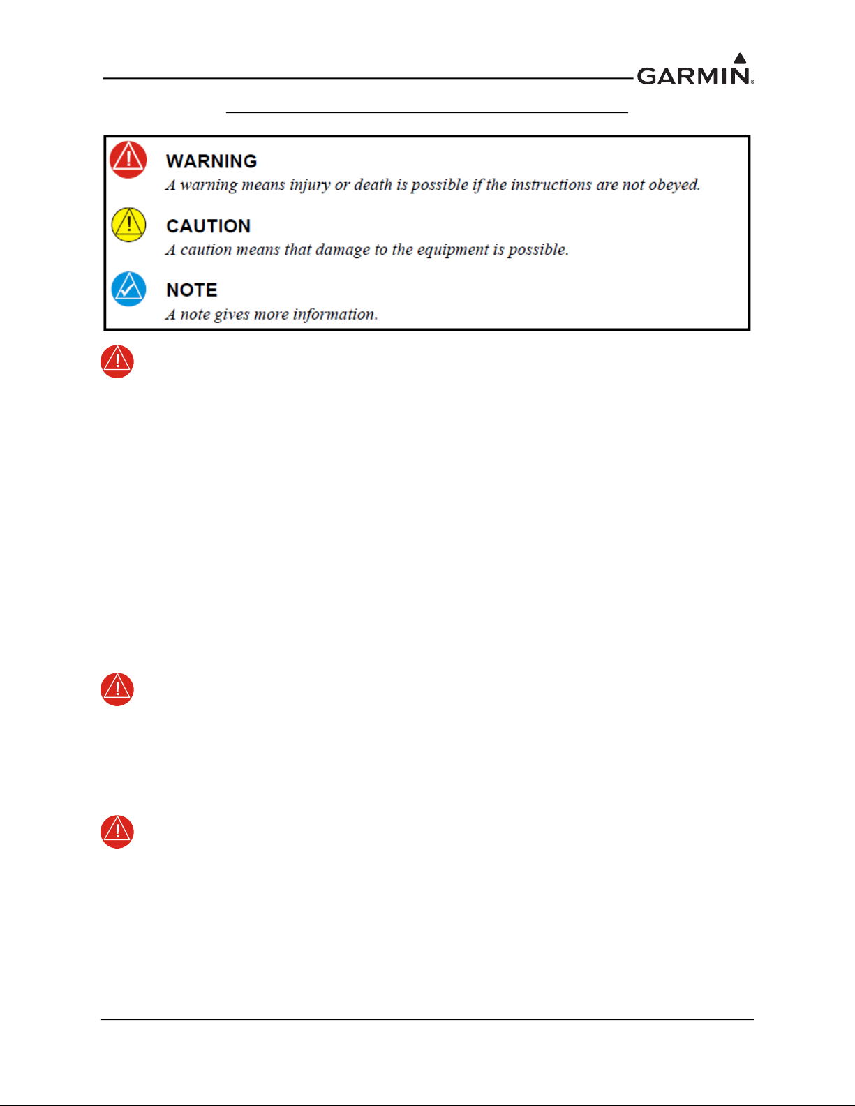
DEFINITIONS OF WARNINGS, CAUTIONS, AND NOTES
WARNING
If these guidelines are not followed, the lithium-ion battery may experience a shortened life
span or may present a risk of damage to the device, fire, chemical burn, electrolyte leak,
and/or injury.
• Do not leave the battery exposed to a heat source or in a high temperature environment. To help
prevent damage, store the battery out of direct sunlight.
• For maximum battery longevity, store within a temperature range of -4˚ to 68˚F (from -20˚ to
20˚C).
• Do not use a sharp object to remove the battery.
• Do not disassemble, puncture, damage, or incinerate the device or battery.
• Keep the battery away from children.
• Only replace the battery with the approved replacement from Garmin. Using another battery
presents a risk of fire or explosion. To purchase a replacement battery, see you Garmin dealer or
the Garmin website.
• Contact your local waste disposal department to dispose of the device and battery in accordance
with applicable local laws and regulations.
WARNING
To reduce the risk of unsafe operation, carefully review and understand all aspects of the
G5 Install Manual & Pilot's Guide documentation and the Pilot’s Operating Handbook of
the aircraft. Thoroughly practice basic operation prior to actual use. During flight
operations, carefully compare indications from the G5 to all available flight displays. For
safety purposes, always resolve any discrepancies.
WARNING
This product, its packaging, and its components contain chemicals known to the State of
California to cause cancer, birth defects, or reproductive harm. This Notice is being
provided in accordance with California Proposition 65. If you have any questions or would
like additional information, please refer to our website at www.garmin.com/prop65
190-02072-01 G5 Installation Manual
Rev. 8 Page ii
CAUTION
The display uses a lens with a special coating that may be sensitive to certain oils, waxes,
and abrasive cleaners. CLEANERS CONTAINING AMMONIA WILL HARM THE ANTIREFLECTIVE COATING. It is very important to clean the lens using a clean, lint-free
cloth and a cleaner that is specified as safe for anti-reflective coatings. Avoid any
chemical cleaners or solvents that can damage plastic components.
CAUTION
The G5 does not contain any user-serviceable parts. Repairs should only be made by an
authorized Garmin service center. Unauthorized repairs or modifications could result in
permanent damage to the equipment and void both the warranty and the authority to
operate this device under FAA, FCC, and other applicable regulations.
NOTE
The G5 may only be installed in type-certificated aircraft in accordance with Garmin STC
SA01818WI.
NOTE
The term LRU, as used throughout this manual is an abbreviation for Line Replaceable
Unit. LRU is used generically in aviation for a product (such as a GSA 28 or GMC 307)
that can be readily "swapped out" (usually as a single component) for troubleshooting/
repair.
NOTE
References to the GMC Mode Controller throughout this manual apply equally to the
GMC 305, GMC 307, and GMC 507 except where specifically noted.
NOTE
Use of the G5 Version 2 Battery (011-03893-01) requires G5 system software v6.80 or
later. It is recommended to update software before installing this battery. To download the
latest approved software visit:https://support.garmin.com/en-US/
.
190-02072-01 G5 Installation Manual
Rev. 8 Page iii

SOFTWARE LICENSE AGREEMENT FOR GARMIN AVIATION PRODUCTS
BY USING THE DEVICE, COMPONENT OR SYSTEM MANUFACTURED OR SOLD BY GARMIN
(“THE GARMIN PRODUCT”), YOU AGREE TO BE BOUND BY THE TERMS AND CONDITIONS
OF THE FOLLOWING SOFTWARE LICENSE AGREEMENT. PLEASE READ THIS AGREEMENT
CAREFULLY. Garmin Ltd. and its subsidiaries (“Garmin”) grants you a limited license to use the
software embedded in the Garmin Product (the “Software”) in binary executable form in the normal
operation of the Garmin Product. Title, ownership rights, and intellectual property rights in and to the
Software remain with Garmin and/or its third-party providers. You acknowledge that the Software is the
property of Garmin and/or its third-party providers and is protected under the United States of America
copyright laws and international copyright treaties. You further acknowledge that the structure,
organization, and code of the Software are valuable trade secrets of Garmin and/or its third-party providers
and that the Software in source code form remains a valuable trade secret of Garmin and/or its third-party
providers. You agree not to reproduce, decompile, disassemble, modify, reverse assemble, reverse
engineer, or reduce to human readable form the Software or any part thereof or create any derivative works
based on the Software. You agree not to export or re-export the Software to any country in violation of the
export control laws of the United States of America.
190-02072-01 G5 Installation Manual
Rev. 8 Page iv

TABLE OF CONTENTS
PARAGRAPH PAGE
1 Installation Information ..................................................................................1-1
1.1 Introduction ..................................................................................................................... 1-1
1.2 G5 Overview.................................................................................................................... 1-1
1.3 Inventory of Materials ..................................................................................................... 1-2
1.4 Unpacking the Unit.......................................................................................................... 1-2
1.5 Garmin Equipment .......................................................................................................... 1-3
1.6 Non-Garmin Equipment .................................................................................................. 1-4
1.7 Garmin Software and Documents.................................................................................... 1-4
2 Installation Preparation...................................................................................2-1
2.1 Electrical Considerations................................................................................................. 2-1
2.2 Wiring/Cabling Considerations ....................................................................................... 2-2
2.3 Mechanical Considerations............................................................................................ 2-10
3 G5 Installation ..................................................................................................3-1
3.1 Primary Functions............................................................................................................ 3-1
3.2 General Specifications..................................................................................................... 3-1
3.3 Installation Information ................................................................................................... 3-1
3.4 Unit Installation ............................................................................................................... 3-2
3.5 Antennas .......................................................................................................................... 3-4
3.6 Mounting Instructions...................................................................................................... 3-5
3.7 Outline and Installation Drawings................................................................................... 3-9
4 GPS Antenna Installation................................................................................4-1
4.1 Non-Garmin Antennas..................................................................................................... 4-1
4.2 Garmin Antennas............................................................................................................. 4-1
5 G5 Pinout ..........................................................................................................5-1
5.1 J51 Connector .................................................................................................................. 5-1
6 Connector Installation Instructions................................................................6-1
6.1 Shield Block Installation Parts ........................................................................................ 6-1
6.2 Lightning Protection Module (LPM) Installation Parts................................................... 6-3
6.3 Shield Termination Technique – Method A.1 (Standard) ............................................... 6-5
6.4 Shield Termination Technique – Method A.2 (Daisy Chain) ......................................... 6-9
6.5 Shield Termination Technique – Method B.1 (Quick Term) ........................................ 6-10
6.6 Shield Termination Technique – Method B.2 (Daisy Chain-Quick Term)................... 6-13
6.7 Daisy Chain between Methods A.1 and B.1.................................................................. 6-14
6.8 Unit ID (Strapping)........................................................................................................ 6-15
6.9 Splicing Signal Wires .................................................................................................... 6-16
190-02072-01 G5 Installation Manual
Rev. 8 Page v

7 Interconnect Drawings.....................................................................................7-1
8 G5 Configuration and Post Installation Checkout........................................8-1
8.1 Recommended Test Equipment....................................................................................... 8-1
8.2 Configuration Mode ........................................................................................................ 8-2
8.3 Software Loading Procedure ........................................................................................... 8-2
8.4 Configuration Pages ........................................................................................................ 8-3
9 Troubleshooting................................................................................................9-1
9.1 General Troubleshooting ................................................................................................. 9-1
9.2 SD Card Slot.................................................................................................................... 9-2
9.3 Unit Communication Error.............................................................................................. 9-2
9.4 Air Data Troubleshooting................................................................................................ 9-2
9.5 Attitude Failure Troubleshooting .................................................................................... 9-2
9.6 Heading Failure Troubleshooting (with GMU 11).......................................................... 9-3
9.7 G5 Data Logging ............................................................................................................. 9-3
9.8 Sending Troubleshooting Data to Garmin....................................................................... 9-3
10 Maintenance..................................................................................................10-1
10.1 G5 Air Data Periodic Maintenance ............................................................................. 10-1
10.2 G5 Battery Periodic Maintenance................................................................................ 10-1
10.3 Return to Service Information ..................................................................................... 10-1
11 Performance Specifications/Licensing/Compliance ..................................11-1
11.1 GPS Specifications ...................................................................................................... 11-1
11.2 G5 Environmental Specifications ............................................................................... 11-1
11.3 G5 Performance Specifications ................................................................................... 11-2
11.4 RS-232 Text Output Format ........................................................................................ 11-3
Appendix A GAD 13 OAT Probe Interface Module Installation ...................A-1
A.1 Equipment Description .................................................................................................. A-1
A.2 General Specifications ................................................................................................... A-2
A.3 Mounting and Wiring Requirements ............................................................................. A-3
A.4 J131 Connector .............................................................................................................. A-5
A.5 Outline and Installation Drawings ................................................................................. A-7
Appendix B GAD 29/29B (ARINC 429 Adapter) Installation ........................B-1
B.1 Equipment Description ...................................................................................................B-1
B.2 Equipment Available ......................................................................................................B-2
B.3 General Specifications ....................................................................................................B-2
B.4 Mounting and Wiring Requirements ..............................................................................B-3
B.5 Connector Pinout ............................................................................................................B-4
B.6 Outline and Installation Drawings ..................................................................................B-8
190-02072-01 G5 Installation Manual
Rev. 8 Page vi

Appendix C GMC 507 (AFCS Mode Controller) Installation ........................C-1
C.1 Equipment Description ...................................................................................................C-1
C.2 General Specifications ....................................................................................................C-2
C.3 Mounting and Wiring Requirements ..............................................................................C-2
C.4 J7001 Connector .............................................................................................................C-4
C.5 Outline and Installation Drawings ..................................................................................C-7
Appendix D GMU 11 (Magnetometer) Installation ........................................D-1
D.1 Equipment Description .................................................................................................. D-1
D.2 Equipment Available ..................................................................................................... D-2
D.3 General Specifications ................................................................................................... D-2
D.4 Unit Installation ............................................................................................................. D-3
D.5 J441 Connector .............................................................................................................. D-5
D.6 Outline and Installation Drawings ................................................................................. D-6
Appendix E GSA 28 (AutoPilot Servo) Installation......................................... E-1
E.1 Equipment Description....................................................................................................E-1
E.2 Equipment Available.......................................................................................................E-2
E.3 General Specifications ...................................................................................................E-2
E.4 Required Equipment........................................................................................................E-4
E.5 Unit Installation...............................................................................................................E-5
E.6 Unit Wiring ...................................................................................................................E-16
E.7 Outline and Installation Drawings ................................................................................E-16
E.8 Connector Pins ..............................................................................................................E-43
190-02072-01 G5 Installation Manual
Rev. 8 Page vii

1 INSTALLATION INFORMATION
1.1 Introduction
This manual is intended to provide mechanical and electrical information for use in the planning and
design of an installation of the Garmin G5 into an aircraft. This manual is not a substitute for an approved
airframe-specific maintenance manual, installation design drawing, or complete installation data package.
Attempting to install equipment by reference to this manual alone and without first planning or designing
an installation specific to your aircraft may compromise your safety and is not recommended. The content
of this manual assumes use by competent and qualified avionics engineering personnel and/or avionics
installation specialists using standard aviation maintenance practices in accordance with Title 14 of the
Code of Federal Regulations and other relevant accepted practices. This manual is not intended for use by
individuals who do not possess the competencies and abilities set forth above.
NOTE
Garmin recommends installation of the G5 by a Garmin-authorized installer. To the extent
allowable by law, Garmin will not be liable for damages resulting from improper or
negligent installation of the G5. For questions, please contact Garmin Product Support at
1-888-606-5482.
1.2 G5 Overview
The G5 is an electronic instrument display capable of operating as a standalone flight display or a
fully integrated backup instrument for G3X systems. It features a bright, sunlight readable, 3.5-inch
color display which is sized to fit in a standard 3-1/8-inch instrument cutout. With integrated attitude/
air data sensors and GPS, the G5 replaces traditional electromechanical standby instruments by
combining essential information into one easy-to-read display. The G5 seamlessly integrates with
other G5 units in the same aircraft and with G3X systems via the CAN network. When installed as
part of a G3X system, the G5 provides a redundant source of attitude and air data to the G3X displays,
and additionally provides backup autopilot control allowing coupled GPS approaches to be flown or
continued in the event that the primary flight display is unavailable. When installed as a standalone
system, the G5 can also perform the autopilot function. In the case of aircraft power loss, the optional
battery backup sustains the G5 flight display with up to 4 hours of emergency power.
190-02072-01 G5 Installation Manual
Rev. 8 Page 1-1

Figure 1-1 G5 Bezel Overview
Power/
Backlight
KnobAmbient
Light
Sensor
microSD™
Card Slot
1.3 Inventory of Materials
This manual provides (and provides references to) mechanical and electrical information required for the
installation of the G5. This manual is intended to be a step-by-step guide to the installation, therefore it is
important that the steps in all sections be performed in order. All materials that are required/optional for
the installation of the G5 are listed in this section (as such, some of the information in this section is
repeated in following sections).
Before beginning the G5 installation, it is recommended that the installer perform a complete inventory of
all materials listed in this section (some materials are optional and may not be applicable to the
installation). Section 1 should be used to verify that all components ordered from Garmin have been
delivered correctly, and to identify any required materials that are not provided by Garmin.
1.4 Unpacking the Unit
Carefully unpack the equipment and make a visual inspection of all contents for evidence of damage
incurred during shipment. If any component of the G5 is damaged, notify the carrier and file a claim. To
justify a claim, save the original shipping container and all packing materials. Do not return any
equipment to Garmin until the carrier has authorized the claim.
Retain the original shipping containers for storage. If the original containers are not available, a separate
cardboard container should be prepared that is large enough to accommodate sufficient packing material to
prevent movement.
190-02072-01 G5 Installation Manual
Rev. 8 Page 1-2
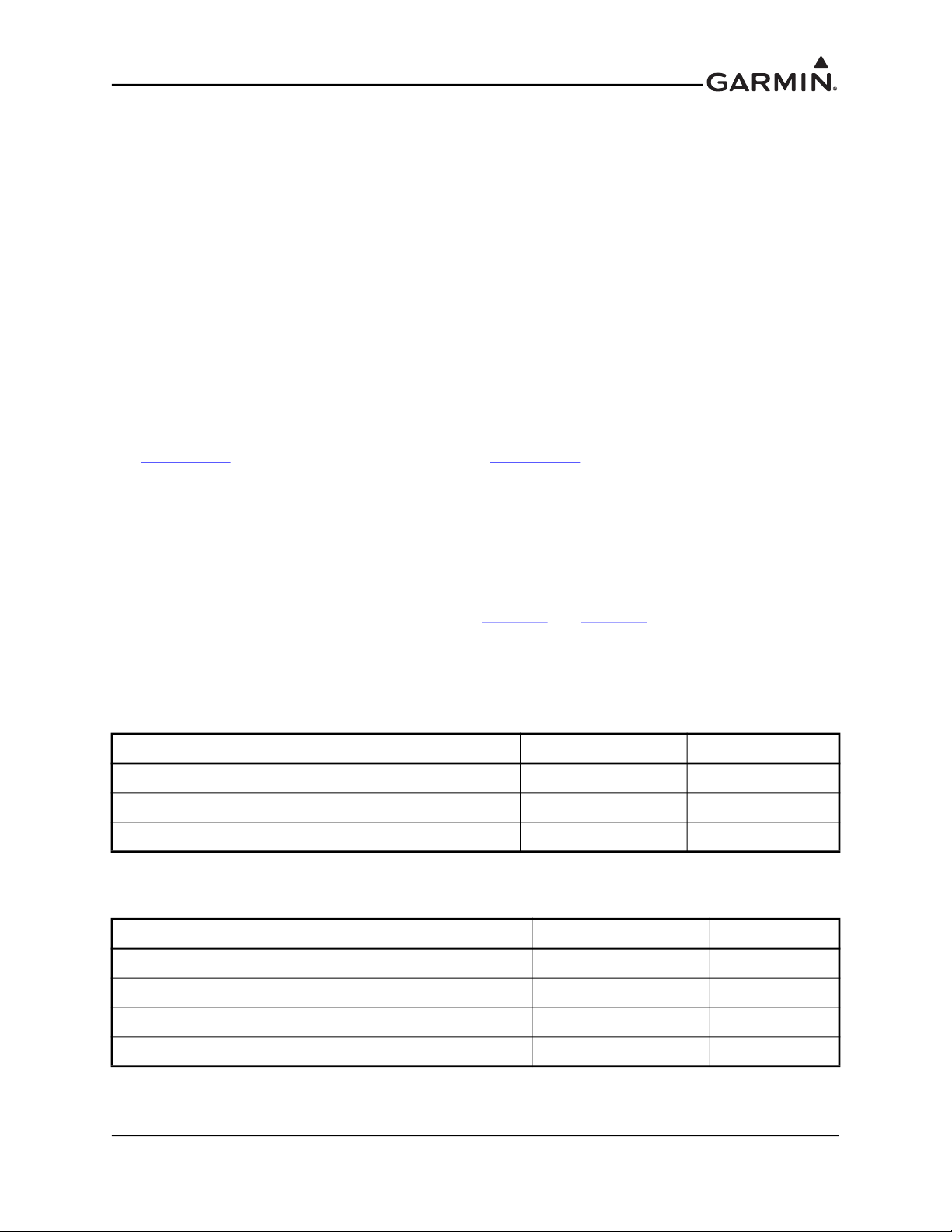
1.5 Garmin Equipment
1.5.1 G5 Installation Equipment
Table 1-1 G5 Installation Equipment
LRU Assembly Part Number Unit Only Part Number
G5, Unit Only 010-01485-00 011-03809-00
Installation Kit, G5 010-12493-10 011-03892-00
Installation Kit, G5, w/LPM 010-12493-11 011-03892-01
Battery Pack, G5 010-12493-00 011-03893-00
Battery Pack, G5, Version 2* 010-12493-01 011-03893-01
*Use of the 011-03893-01 requires G5 system software v6.80 or later..
1.5.2 Optional GPS Antenna
The G5 includes a built-in GPS receiver with an internal antenna that can be used in many installations. A
Garmin or non-Garmin GPS antenna is optional for G5 installations when not using the G5's internal GPS
antenna. See Section 4
1.5.2.1 Antenna Brackets/Doubler Plates
for supported antennas and antenna requirements.
See the G3X/G3X Touch Installation Manual (190-01115-01) for detailed information.
1.5.3 Optional Garmin LRUs
The G5 can be installed in a standalone configuration or as part of the G3X system. Optional Garmin
LRUs (Line Replaceable Units) that can be installed with the G5 in the standalone configuration are listed
below. If any of these LRUs are to be used in this installation, verify that all required installation materials
such as connector kits have been acquired. Refer to the G3X/G3X Touch Installation Manual
(190-01115-01) available at https://support.garmin.com/support/manuals
for additional installation
information for the G3X system.
Optional Garmin LRUs:
• GAD 13 OAT Probe Interface Module
• GAD 29 ARINC 429 Adapter (required for connection to IFR Navigator)
• GMC 305 Mode Controller
• GMC 307 Mode Controller
• GMC 507 Mode Controller
• GMU 11 Magnetometer
• GSA 28 Autopilot Servo
190-02072-01 G5 Installation Manual
Rev. 8 Page 1-3

1.6 Non-Garmin Equipment
1.6.1 Wiring/Cabling Considerations
The installer will provide all wiring and cabling unless otherwise noted.
1.6.2 Contact and Crimp Tools
Recommended crimp tools used to build the wiring harnesses for the G5 are listed in Table 1-2. Equivalent
crimp tools may also be used.
Table 1-2 Pin Contact and Crimp Tools Part Numbers
Contact Type
Socket, Size 20,
20-24 AWG
Garmin Contact
Part Number
336-00022-02
Recommended
Positioner
M22520/2-08,
Daniels K13-1
Recommended
Insertion/
Extraction Tool
M81969/1-04 for
size 22D pins and
M81969/1-02 for
size 20 pins
Recommended
Hand Crimping
Tool
M22520/2-01,
Daniels AFM8
NOTE
Non-Garmin part numbers shown are not maintained by Garmin and consequently are subject
to change without notice.
1.6.3 BNC Connectors
BNC connectors may be required to terminate the GPS antenna cable, depending upon which antenna is
used. Check the GPS antenna installation instructions for detailed information.
1.6.4 Hex Driver
A 3/32” hex drive tool is required to secure the G5 to the panel as described in Section 3
1.6.5 SD Card
A microSD™ card can be used with the G5 for software updates and data logging. Garmin recommends
SanDisk® brand SD cards up to 32 GB.
, G5 Installation.
1.6.6 Pneumatic Hoses and Connectors
Air hoses and fittings are required to connect pitot and static air to the G5. The G5 has a female 1/8-27
ANPT fitting for each pitot and static port. Use appropriate aircraft fittings to connect to pitot and static
system lines.
1.6.7 Silicone Fusion Tape
Use Garmin Part Number 249-00114-00 or similar to wrap the wiring/cable bundles.
1.7 Garmin Software and Documents
The G5 unit software and a panel cut-out DXF file are available for free download from
http://www8.garmin.com/support/collection.jsp?product=010-01485-00
190-02072-01 G5 Installation Manual
Rev. 8 Page 1-4
.
2 INSTALLATION PREPARATION
This section provides electrical and mechanical information needed for planning the physical layout of the
G5 installation. Use the information in Section 2 to become familiar with all aspects of the installation
before actually beginning the physical installation of any equipment into the aircraft. Garmin recommends
that the installer become familiar with all sections of this document before beginning the installation. In
general terms, the below steps are recommended to be followed in order.
1. Inventory of all needed parts
2. Planning/layout of the installation
3. Installation of LRUs, antennas, and sensors
4. Construction of wiring harness, cables, and connectors
5. Software installation/configuration
6. Post-installation checkout procedure and calibration
2.1 Electrical Considerations
This section presents information required for planning the electrical layout of the G5 installation.
CAUTION
To avoid damage to the G5 and other LRUs, take precautions to prevent Electro-Static
Discharge (ESD) when handling connectors and associated wiring. ESD damage can be
prevented by touching an object that is of the same electrical potential as the LRU before
handling the LRU itself.
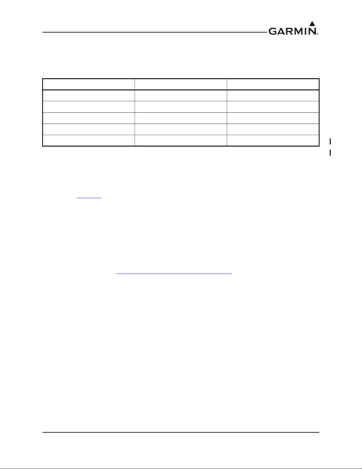
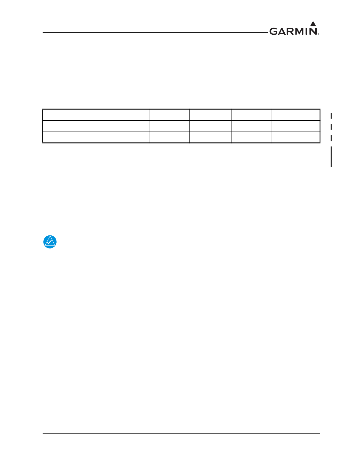
2.1.1 Power Specifications
The G5 is capable of operating at either 14 or 28 VDC. Table 2-1 lists the supply voltage and current draw
information for the G5. Use this information when determining power supply requirements. All installed
electrical appliances must be considered when determining total power requirements.
The specified current draw listed in Table 2-1 is measured with the display backlight set to 100%.
Table 2-1 G5 Power Requirements
Configuration 14 V (Maximum) 14 V (Typical) 28 V (Maximum) 28 V (Typical)
G5 Only
G5 w/Battery
3.5 W,
0.250 Amp
10.7 W,
0.760 Amp
2.8 W,
0.200 Amp
2.8 W,
0.200 Amp
3.5 W,
0.125 Amp
10.7 W,
0.380 Amp
2.8 W,
0.100 Amp
2.8 W,
0.100 Amp
190-02072-01 G5 Installation Manual
Rev. 8 Page 2-1
2.2 Wiring/Cabling Considerations
Section 5 lists the pin information for the G5 and Section 7 contains interconnect drawings. It is
recommended that all LRUs be installed prior to constructing the wiring harnesses and cables.
Use MIL-W-22759/16 (or other approved wire) AWG #22 or larger wire for all non-shielded connections
unless otherwise specified. Use MIL-C-27500 (or other approved wire) AWG #22 or larger wire for all
shielded connections unless otherwise specified. The supplied standard pin contacts are compatible with
up to AWG #20 wire. In cases where some installations have more than one LRU sharing a common
circuit breaker, sizing and wire gauge is based on aircraft circuit breaker layout, length of wiring, current
draw on units, and internal unit protection characteristics.
RG400 or RG142 coaxial cable with 50 Ω nominal impedance and meeting applicable aviation regulations
should be used when installing an optional external GPS antenna.
2.2.1 Wiring Harness Installation
Use cable meeting the applicable aviation regulation for the interconnect wiring. Any cable meeting
specifications is acceptable for the installation. When routing cables, observe the following precautions:
• All cable routing should be kept as short and as direct as possible.
• Check that there is ample space for the cabling and mating connectors.
• Avoid sharp bends in cabling.
• Avoid routing near aircraft control cables.
• Avoid routing cables near heat sources, RF sources, EMI interference sources, power sources (e.g.
400 Hz generators, trim motors, etc.) or near power for fluorescent lighting.
• Route the GPS antenna cable as far as possible away from all COM transceivers and other antenna
cables.
The installer shall supply and fabricate all of the cables. Electrical connections are made through the D
subminiature connector. Section 5
Required connectors and associated hardware are supplied with the connector kit.
Contacts for the connectors must be crimped onto the individual wires of the aircraft wiring harness.
Table 1-2
lists contact part numbers (for reference) and recommended crimp tools.
defines the electrical characteristics of all input and output signals.
CAUTION
Check wiring connections for errors before connecting any wiring harnesses. Incorrect
wiring could cause internal component damage.
2.2.2 CAN Bus Considerations
The primary digital interface used to exchange data between the G5 and other LRUs is the Controller Area
Network, also known as the CAN bus. CAN was developed by Bosch GmbH in the 1980s, and its
specifications are currently governed by ISO 11898-2. CAN is widely used in aviation, automotive, and
industrial applications due to its simplicity and reliability.
190-02072-01 G5 Installation Manual
Rev. 8 Page 2-2
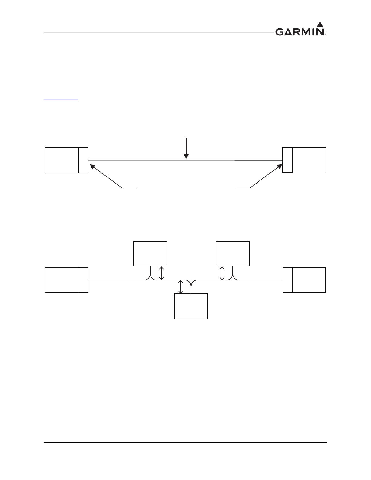
2.2.3 CAN Bus Architecture
LRU
LRU
TERMINATION CONNECTIONS
CAN BUS BACKBONE: CONSISTS OF TWISTED, SHIELDED PAIR
WIRING CONNECTED TO CAN-H AND CAN-L OF EACH LRU, AND
PROPERLY TERMINATED LRUs ON BOTH ENDS OF BUS.
TERM
TERM
The electrical architecture of the CAN bus takes the form of a linear “backbone” consisting of a single
twisted wire pair with an LRU connected (terminated) at each end (Figure 2-1). The overall length of the
CAN bus from end to end should be 66 feet (20 meters) or less. At each of the two extreme ends of the
CAN bus, a 120 Ω resistor is installed to “terminate” the bus. Termination resistors are provided either
within the LRUs themselves, or via termination adapters that plug into an LRUs CAN connection (see
Section 2.2.5
).
Figure 2-1 CAN Bus Backbone
Multiple LRU's may be connected in a daisy chain manner along the backbone of the CAN bus
(Figure 2-2).
LRU LRU
Max. node length
LRU
TERM
1 foot (0.3 meter)
LRU
TERM
LRU
Figure 2-2 CAN Bus Node Connections
Daisy-chained LRUs (LRUs not at the extreme ends of the CAN bus) connect to the CAN backbone
through short “stub” or “node” connections (Figure 2-3). The length of each node connection should be
kept as short as possible, and should not exceed 1 foot (0.3 meter). The best way to connect devices
between the ends of the CAN bus while maintaining short stub node lengths is to splice the connections as
close to the device as practical. Unshielded wire sections should be kept as short as practical.
Multiple devices must not connect to the CAN bus backbone at the same point. Rather than splicing two or
more stub node connections together, the CAN bus should instead be daisy-chained from one device to the
next (Figure 2-3).
190-02072-01 G5 Installation Manual
Rev. 8 Page 2-3
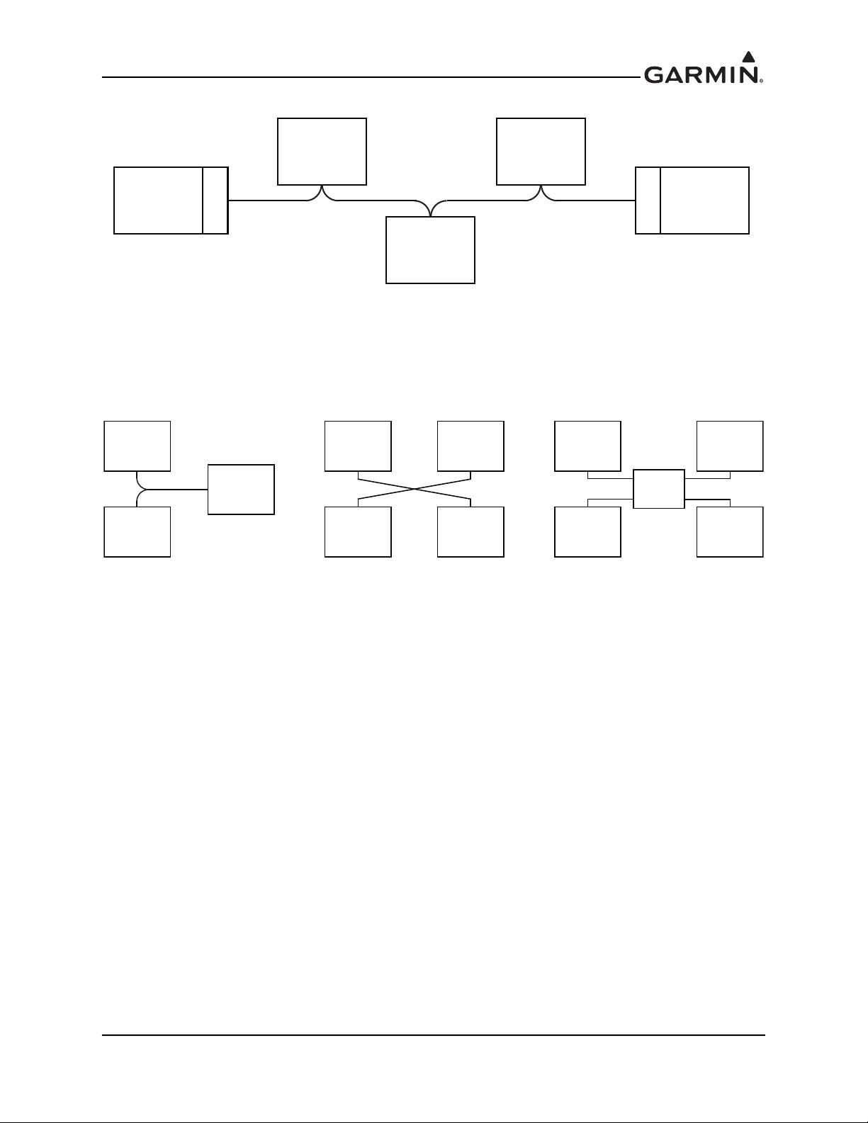
A
LRU LRU
LRU
LRU
LRU
AVOID “T” OR “Y” SHAPE
LRULRU
LRU LRU
AVOID STAR SHAPE
LRULRU
LRU
LRU
HUB
DEVICE
DO NOT USE THIRD-PARTY
HUB DEVICES
LRU
TERM
LRU
TERM
LRU
LINEAR CAN BACKBONE, DAISY-CHAINED CONNECTIONS WITH SHORT STUB
NODE LENGTHS. MULTIPLE LRUs ARE NOT CONNECTED TO THE BACKBONE
T THE SAME LOCATION.
Figure 2-3 Correct CAN Wiring Example
Figure 2-4 Incorrect CAN Wiring Example
2.2.4 CAN Bus Wiring
Wiring used for the CAN bus should be shielded twisted-pair cable, MIL-C-27500 or equivalent. 22 AWG
or larger wire is recommended for physical robustness and ease of installation. The shields for each CAN
bus wire segment should be interconnected, forming a continuously connected shield from one end of the
CAN bus to the other (Figure 2-5). At a minimum, the CAN bus shield should always be grounded to the
device connector backshells at the two extreme ends of the bus, but it is recommended to also ground the
shield at all other devices on the CAN bus.
Rev. 8 Page 2-4
190-02072-01 G5 Installation Manual
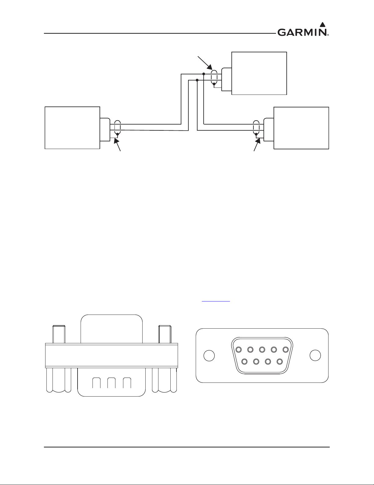
Figure 2-5 CAN Bus Shield Grounding
CAN-H AND CAN-L WIRING SHOWN IS TWISTED SHIELDED PAIRCAN-H AND CAN-L WIRING SHOWN IS TWISTED SHIELDED PAIR
CAN BUS TERMINATIONCAN BUS TERMINATION
CAN-HCAN-H
CAN-LCAN-L
SHIELD GROUNDSHIELD GROUND
CAN BUS TERMINATIONCAN BUS TERMINATION
CAN-HCAN-H
CAN-LCAN-L
SHIELD GROUNDSHIELD GROUND
SHIELD GROUNDED AT EACH END OF CAN BUS REQUIREDSHIELD GROUNDED AT EACH END OF CAN BUS REQUIRED
DAISY-CHAINEDDAISY-CHAINED
LRU ON CAN BUSLRU ON CAN BUS
CAN-HCAN-H
CAN-LCAN-L
SHIELD GROUNDSHIELD GROUND
SHIELD GROUNDED AT EACHSHIELD GROUNDED AT EACH
DAISY-CHAINED LRU, RECOMMENDEDDAISY-CHAINED LRU, RECOMMENDED
GARMIN CAN TERMINATOR
For proper CAN bus operation, it is important for all devices on the CAN bus to share a common power
ground reference. Connect all LRU power ground pins to a single common ground point - do not use local
ground points or use the aircraft structure as a ground return path.
2.2.5 CAN Bus Termination
At each of the two extreme ends of the CAN bus backbone, a 120 Ω resistor is installed to terminate the
bus. Separate resistors are not required, termination resistors are provided either within the LRUs
themselves, or via termination adapters that plug into an LRU’s CAN connection.
• The GAD 13, GAD 29, GMU 11, GPS 20A, and G5 installation kits each provide a 9-pin
termination adapter that provides CAN bus termination when attached between the LRU and the
cable assembly. The termination adapter contains a 120 Ω resistor that is connected between pins
1 and 2 (Figure 2-6).
• The GMC 507 and GSA 28 contain a 120 Ω resistor inside the unit that provides termination when
the two CAN-TERM pins are connected together (Figure 2-7
).
Figure 2-6 CAN Bus Termination (011-02887-00) for the G5, GAD 13, GAD 29, GMU 11, and
190-02072-01 G5 Installation Manual
Rev. 8 Page 2-5
GPS 20A
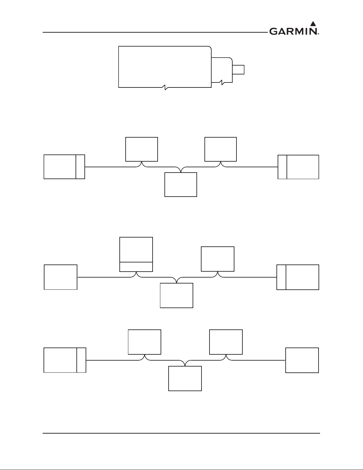
Figure 2-7 CAN Bus Termination for the GSA 28
GSA 28 SERVO
CAN_TERM_1 3
CAN_TERM_2 4
Both ends of the CAN bus should be terminated (Figure 2-8) and devices that are not at the ends of the
CAN bus should not be terminated (Figure 2-9).
LRU LRU
LRU
TERM
LRU
CORRECT - CAN BUS TERMINATED AT EACH END OF THE BACKBONE
Figure 2-8 Correct CAN Bus Termination Example
LRU
TERM
LRU
LRU
TERM
LRU
LRU
TERM
LRU
INCORRECT - ONE OF THE TERMINATIONS IS NOT AT THE END OF THE BACKBONE
LRU
190-02072-01 G5 Installation Manual
Rev. 8 Page 2-6
LRU LRU
LRU
TERM
LRU
INCORRECT - ONLY ONE END OF THE BACKBONE IS TERMINATED
Figure 2-9 Incorrect CAN Bus Termination Example
2.2.6 CAN Bus LRU Removal Guidelines
The following should be considered when removing an LRU from the ends of the CAN bus.
• GAD 13, GAD 29, GMU 11, GPS 20A, G5, or other devices that use the 9-pin CAN termination
adapter: The CAN bus will remain terminated as long as the CAN termination adapter is left
connected to the cable assembly.
• GMC 507: The CAN Bus will be unusable until the LRU is reconnected or the bus is properly
terminated at both ends of the CAN backbone.
• GSA 28: A removal adapter (part number 011-03158-00) is provided with each GSA 28 connector
kit. This adapter can be used when a GSA 28 is removed from the aircraft. The removal adapter
keeps the node on the CAN bus in the same state as when the servo was installed (either terminated
or un-terminated). The removal adapter also allows trim signals to pass through when no servo is
installed.
2.2.7 CAN Bus Installation Guidelines
For maximum reliability of the CAN bus, the following guidelines should be followed:
• The CAN bus backbone must be a single linear path with exactly two distinct ends. CAN bus
connections should be daisy-chained from device to device. Avoid “T”, “Y”, and "star" topologies,
and do not use a hub device (Figure 2-4
).
• The overall length of the bus should not exceed 66 feet (20 meters).
• Keep all stub node connections as short as practical. The maximum length of any stub node
connection is 1 foot (0.3 meter).
• Avoid connecting more than one device to the CAN bus backbone at the same point. Instead, daisy
chain the CAN bus backbone from one device to the next.
• Observe proper wiring, shielding, and grounding requirements described in Section 2.2.2
• Terminate the CAN bus at the two extreme ends of the bus, as described in Section 2.2.3
• When adding a new device to the CAN bus, evaluate proposed modifications to the CAN bus
wiring connections to ensure compliance with all of the preceding requirements.
.
.
2.2.8 CAN Bus Troubleshooting
The CAN bus is very simple, and a properly installed CAN bus is very reliable. If problems are occurring,
the following steps can help to identify the issue.
1. Review the status LED of devices on the CAN bus such as the GSA 28 servos. The status LED
indications are listed in Table 2-2.
Table 2-2 Status LED Indications
LED Indication Description
No Light No power
Steady Green On but not communicating via CAN bus
Flashing Green On and communicating via CAN bus
Red Hardware fault
Alternating Red/Green
CAN bus network error (two identical LRUs are configured with
the same unit ID)
2. Make sure that the CAN bus is daisy-chained between CAN devices around the system, and that
CAN devices are not connected via a single point (star topology) or routed through a hub device.
190-02072-01 G5 Installation Manual
Rev. 8 Page 2-7

This can cause unwanted signal reflections and “orphan” some devices on the bus and prevent
their communication.
3. Make sure the CAN bus is terminated in only two locations, and only at the extreme ends of the
CAN bus.
4. With power removed, remove the CAN bus connector from one of the devices that is not located at
either of the extreme ends of the CAN bus.
a) Using an ohm meter, verify that the resistance between the CAN-H and CAN-L pins on the
connector is 60 Ω. This will verify that the CAN backbone is properly terminated at each
end (two 120 Ω terminating resistors in parallel).
b) A resistance of 120 Ω indicates that one of the two required CAN terminations is missing.
c) A resistance of 40 Ω or less indicates that too many terminations are installed.
5. Verify that the CAN-H and CAN-L signals are not swapped, shorted together, or open-circuited at
any LRU connector.
6. Verify that the CAN-H and CAN-L signals are not shorted to ground (this can happen when
shielded wire is installed incorrectly).
7. Highlight each device on the configuration mode Device Information page and verify that the
value displayed for Network Error Rate is a steady 0%.
Figure 2-10 Network Error Rate
8. Power up only the #1 G5 unit and one other CAN device at a time, and verify the connection
quality for each device. Sometimes a device will communicate only when it is the only powered
device on the CAN bus, if one or more of the above issues is present. Evaluating each CAN
device in turn can help narrow down a problem.
9. It is very important for each device on the CAN bus to share a common power/signal ground.
Ground potential differences between devices on the CAN bus can cause communication errors.
Ground devices to a common ground bus, not to the airframe or to multiple grounding buses.
190-02072-01 G5 Installation Manual
Rev. 8 Page 2-8
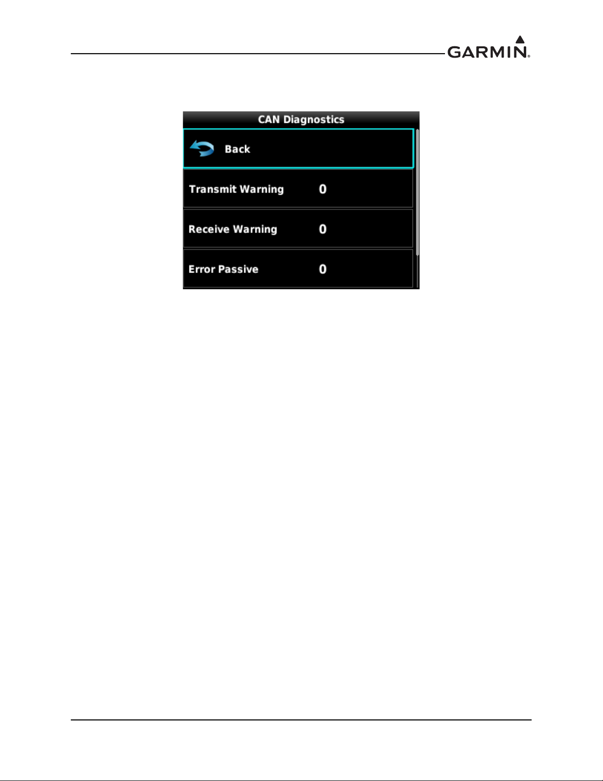
10. Advanced CAN diagnostics are available by selecting Device Information, Diagnostics, CAN
Network. Any increase of these parameters above zero is an indication of a CAN bus issue.
Figure 2-11 CAN Diagnostic Page
2.2.9 Cable Connector Installation
A coaxial cable connection is required for the optional external GPS antenna.
1. Route the coaxial cable to the unit location. Secure the cable in accordance with good aviation
practices.
2. Trim the coaxial cable to the desired length and install the BNC connector. If provided, follow the
connector manufacturer’s instructions for cable preparation.
190-02072-01 G5 Installation Manual
Rev. 8 Page 2-9
2.3 Mechanical Considerations
This section presents all information required for planning the physical layout of the G5 installation.
2.3.1 Physical Specifications
Use Table 2-3 to determine panel requirements. All width, height, and depth measurements are taken with
unit mounting ring and connectors (if applicable).
Table 2-3 G5 Physical Specifications
Configuration Width Height Depth* Unit Weight Total Weight**
G5 3.42 in 3.60 in 2.61 in 0.6 lb 0.7 lb
G5 with Battery*** 3.42 in 3.60 in 3.03 in 0.8 lb 1.0 lb
*Depth behind aircraft panel
**Weight includes connector and mounting ring (011-03892-00/-01 installation kit)
***Applies to 011-03893-00/01 battery packs
2.3.2 Cooling Requirements
While no forced cooling air is required for the G5, it is highly recommended that the air behind the panel
be kept moving (by ventilation or a fan). Units tightly packed in the avionics stack heat each other through
radiation, convection, and sometimes by direct conduction. Even a single unit operates at a much higher
temperature in still air than in moving air. Fans or some other means of moving the air around electronic
equipment are usually a worthwhile investment.
NOTE
Avoid installing LRUs near heat sources. If this is not possible, ensure that additional cooling
is provided. Allow adequate space for installation of cables and connectors. The installer will
supply and fabricate all of the cables. All wiring should be in accordance with FAA
AC 43.13-1B and AC 43.13-2B.
2.3.3 Compass Safe Distance
After reconfiguring the avionics in the cockpit panel, if the unit is mounted less than 12 inches from the
compass, recalibrate the compass and make the necessary changes for noting correction data.
190-02072-01 G5 Installation Manual
Rev. 8 Page 2-10
3 G5 INSTALLATION
The G5 can be installed as a standalone flight display or a fully integrated backup instrument in the G3X
system. This section contains general information as well as installation information for the G5.
3.1 Primary Functions
• Attitude (roll, pitch, and yaw)
• Air data (altitude and airspeed)
• Slip/skid and turn coordinator
• GPS (ground speed and ground track)
• Autopilot control (when installed with optional equipment)
• Optional battery backup with up to 4 hours of emergency power
• RS-232 and CAN communication interfaces
• Course and navigation display (when installed with optional equipment)
• Magnetic heading (when installed with optional equipment)
3.2 General Specifications
See Section 2.1.1 for power/current specifications, and Section 2.3.1 for dimension/weight specifications.
3.3 Installation Information
3.3.1 Required Equipment
One installation kit (Table 3-1) is required to install each G5 unit. The G5 mounting ring is included in the
installation kit to mount the G5 to the aircraft panel and to reinforce the panel cutout in thin panel
installations. The installation kit is not included with the G5.
An optional alternate installation kit is also available (Table 3-3
and Table 3-4). This kit incorporates a
lightning protection module (LPM) into the backshell of the D-sub. The LPM provides additional
protection devices for the CAN signals and aircraft power 1 input.
Table 3-1 Contents of the G5 Installation Kit (011-03892-00)
Item Garmin P/N Quantity
Connector Kit, 9 Pin, w/CAN Term 011-03002-00 1
Mounting Ring, G5 115-02251-03 1
Screw, 6-32, 0.500" 211-60207-12 3
Table 3-2 Contents of the Connector Kit (011-03002-00)
Item Garmin P/N Quantity
Sub-Assy, Bkshl w/Hdw, Jackscrew, 9 pin 011-01855-00 1
Sub Assy, CAN Termination Kit 011-02887-00 1
Conn, Rcpt, D-Sub, Crimp Socket, 9 Ckt 330-00625-09 1
Contact, Sckt, D-Sub, Crimp, Size 20, 20-24 AWG 336-00022-02 9
190-02072-01 G5 Installation Manual
Rev. 8 Page 3-1
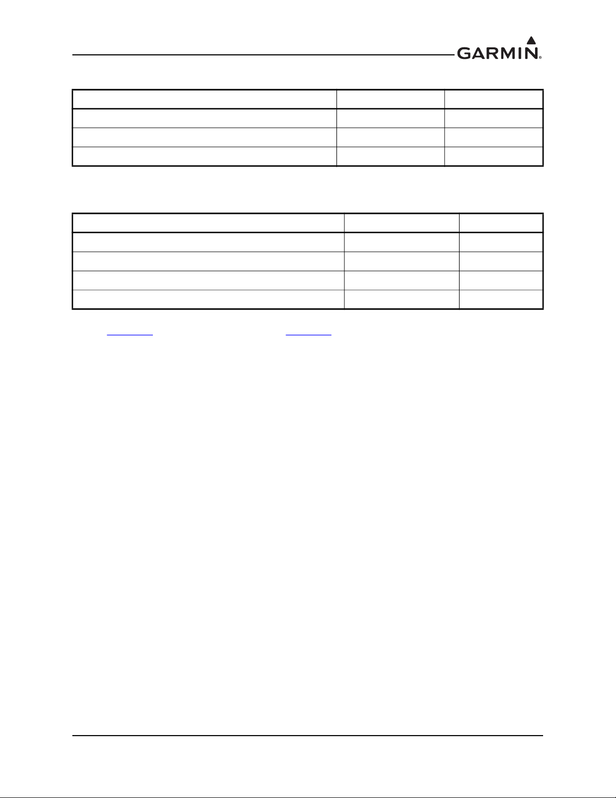
Table 3-3 Contents of the G5 LPM Installation Kit (011-03892-01)
Item Garmin P/N Quantity
Connector Kit, 9 Pin, w/CAN Term, w/LPM 011-03002-20 1
Mounting Ring, G5 115-02251-03 1
Screw, 6-32, 0.500" 211-60207-12 3
Table 3-4 Contents of the LPM Connector Kit (011-03002-20)
Item Garmin P/N Quantity
Sub-Assy, Bkshl w/Hdw, Jackscrew, 9 pin, w/LPM** 011-01855-20 1
Sub Assy, CAN Termination Kit* 011-02887-00 1
Conn, Rcpt, D-Sub, Crimp Socket, 9 Ckt 330-00625-09 1
Contact, Sckt, D-Sub, Crimp, Size 20, 20-24 AWG 336-00022-02 9
*Not all items included in kit P/N 011-02887-00 are used in this installation
**See Figure 6-2
for connector assembly. See Figure 7-3 for LPM Wiring Interface
190-02072-01 G5 Installation Manual
Rev. 8 Page 3-2

3.3.2 Additional Equipment Required
A 3/32” hex drive tool is required to secure the G5 to the panel as described in Section 3.6.3
Figure 3-4
Air hoses and fittings are required to connect pitot air and static air to the G5. The G5 uses a female 1/8-27
ANPT fitting for each of these ports. Use appropriate aircraft fittings to connect to pitot and static system
lines.
.
and shown in
3.4 Unit Installation
Fabrication of a wiring harness is required. Sound mechanical and electrical methods and practices are
recommended for installation of the G5. Refer to Section 2.2
for pinouts.
Connector kits include backshell assemblies. Garmin’s backshell connectors give the installer the ability
to quickly and easily terminate shield grounds at the backshell housing. Instructions needed to install the
Jackscrew Backshell and Shield Block Ground can be found in Section 6
3.4.1 Mounting Requirements
The G5 includes an extremely sensitive inertial measurement unit. Consider the following when selecting
a mounting location:
• Mount the G5 with the connector aligned to within 15.0° of the longitudinal axis of the aircraft
(display bezel parallel to the wing spar). Configuration allows for direct manual entry of the
present yaw offset when the instrument panel to which the G5 is mounted is not perpendicular to
the aircraft centerline.
• The G5 should be rigidly mounted to the aircraft panel. To avoid degraded accuracy, the aircraft
panel should be rigid and panel flexing should be minimized.
• The G5 should be mounted to the aircraft panel with the connector facing toward the front of the
aircraft.
• The G5 should be mounted within 13 feet (4 meters) longitudinally of the aircraft CG (center of
gravity). In cases where the longitudinal distance from the CG is planned to be greater than 6.5
feet (2 meters), it is preferable to mount the G5 forward of the aircraft CG, if possible, to improve
autopilot performance.
• To prevent degraded accuracy, avoid placing the G5 near areas that are prone to severe vibration.
• The G5 must be leveled to within 30.0° of the flight level cruise attitude. An aircraft leveling and
offset calibration procedure must additionally be carried out prior to flight.
• The mounting location for the G5 should be protected from rapid thermal transients, in particular
large heat loads from nearby high-power equipment.
• Avoid placing the G5 within 1 inch of magnetically mounted antennas, speaker magnets, or other
strongly magnetic items.
for wiring considerations, and to Section 5
.
3.4.2 Unit Mounting
For final installation and assembly, refer to the outline and installation drawings in Section 3.7
1. Mount the G5 in a suitable location using the installation kit (Table 3-1
Section 3.4.1.
2. Assemble the wiring harness and backshell connector.
3. Assemble the pneumatic hoses and connector.
4. Connect the CAN terminator if required (see Section 2.2.5
5. Connect the backshell connector and hoses.
190-02072-01 G5 Installation Manual
Rev. 8 Page 3-3
).
) per the requirements in
.
3.4.3 Pneumatic Plumbing
The G5 has two ports that are connected to the aircraft’s pitot and static pressure sources. The ports are
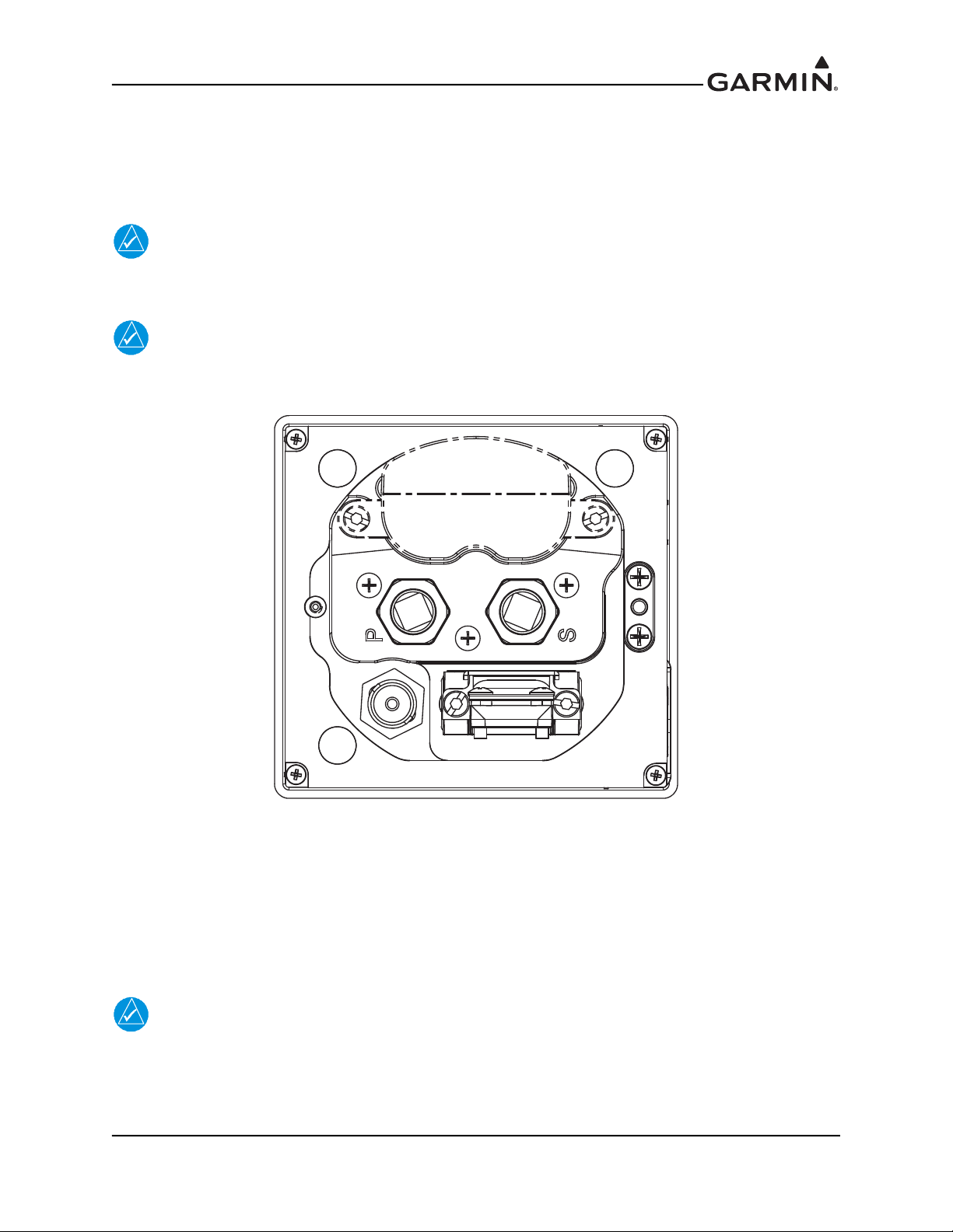
labeled on the unit using the abbreviations “P” and “S” respectively (Figure 3-1). The pressure ports have
1/8-27 ANPT female threads. The mating fitting must have 1/8-27 ANPT male threads.
NOTE
The temporary port plugs attached to the pressure ports on a new G5 are not suitable for flight
and must be removed prior to the installation of G5 into the aircraft.
NOTE
In an installation with dual G5 units, pitot/static plumbing must be connected to both units.
Figure 3-1 G5 Air Hose Fitting Locations
Use appropriate air hoses and fittings to connect the pitot and static lines to the unit. Avoid sharp bends in
the tubing and attempt to route hoses away from aircraft control cables. The G5 should not be at the low
point of the pneumatic plumbing lines to avoid moisture or debris collecting at or near the unit. Ensure that
no deformations of the airframe surface have been made that would affect the relationship between static
air pressure and true ambient static air pressure for any flight condition. Refer to CFR Part 43, Appendix E
for approved practices while installing hoses and connections.
NOTE
A G5 installed as a standalone unit may optionally be configured to disable its internal air
data sensors. In this case, no connection to the aircraft's pitot/static system is required. If not
connected, the pitot/static fittings on the G5 should be covered with dust caps. A G5 with air
data disabled does not support autopilot functionality.
190-02072-01 G5 Installation Manual
Rev. 8 Page 3-4

3.4.4 Pneumatic Connections
The following steps should be used to aid in the fabrication of pneumatic hose connections and in attaching
the aircraft pitot pressure source and aircraft static pressure sources to the G5.
NOTE
Whenever the aircraft is connected to a pitot-static tester, such as during Part 43 Appendix E
altimeter tests, the pitot port must be covered by a pitot adapter that is controlled by the pitotstatic tester. Failure to do so will result in overpressuring and damaging the internal airspeed
sensor.
NOTE
Use of different colored tubing is recommended for static and pitot plumbing to avoid
plumbing connection errors. Incorrect plumbing connections will result in erroneous air data
information calculated by the G5.
Observe the following cautions when connecting pneumatic lines:
1. Make sure the aircraft static pressure port is plumbed directly to the unit static pressure input port
and the aircraft pitot pressure port is plumbed directly to the unit pitot pressure input port.
2. Seal the threads of pneumatic fittings at the connector ports. Use caution to ensure there are no
pneumatic leaks.
3. Use care to avoid getting fluids or particles anywhere within the pneumatic lines connected to the
G5.
3.5 Antennas
Refer to Section 4 for antenna installation information.
190-02072-01 G5 Installation Manual
Rev. 8 Page 3-5
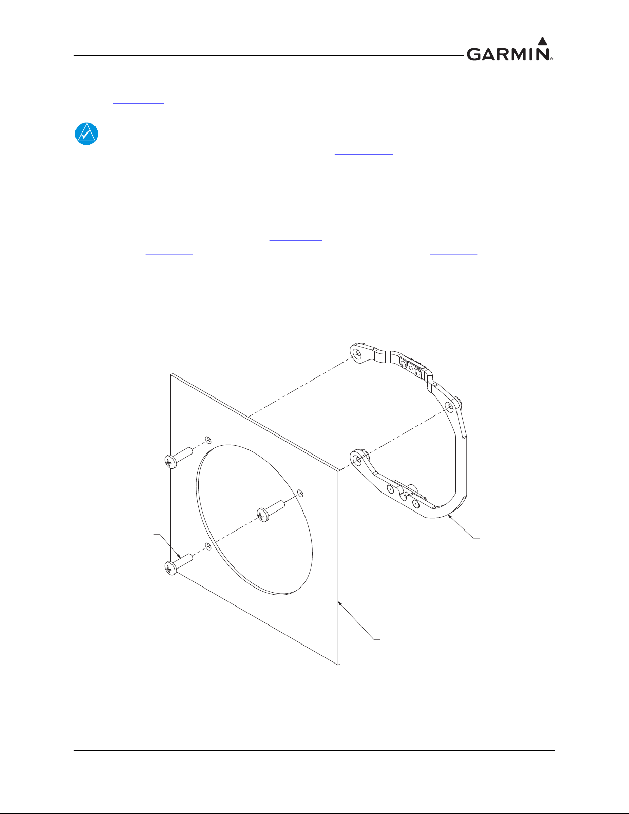
3.6 Mounting Instructions
G5 MOUNTING RING
115-02251-03
AIRCRAFT PANEL
MOUNTING SCREW,
#6-32 PHP x 0.50[12.7]
211-60207-12
3 PLACES
Refer to Section 3.7 for outline and installation drawings.
NOTE
In addition to the mounting requirements listed in Section 3.4.1, it is critical that the G5 be
installed with its display bezel perpendicular to the aircraft's longitudinal axis (display
bezel parallel to the wing spar) and as close to level in the roll axis as possible. Small roll
offsets, and pitch offsets up to 30 , can be corrected for during calibration.
3.6.1 Panel Cutout Template
The G5 Mounting Ring (115-02251-03) or Figure 3-10
for cutout. See Figure 3-9
for complete cutout dimensions (the dimensions on Figure 3-9 are to verify the
can be used as a template when marking the panel
accuracy of the printout only).
3.6.2 Mounting Ring Installation
Secure the mounting ring to the aircraft panel using the supplied #6-32 pan head Phillips mounting screws.
Evenly torque the mounting screws to 10-12 in-lb.
Figure 3-2 G5 Mounting Ring
190-02072-01 G5 Installation Manual
Rev. 8 Page 3-6
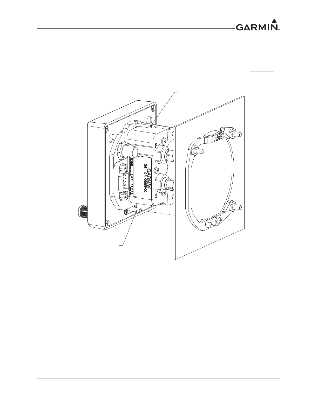
3.6.3 Unit Installation
The G5 is installed by inserting the alignment pin located at the top of the unit into the mating hole in the
mounting ring, pushing the unit flush with the instrument panel, and fastening the captive 3/32” hex socket
head screw to the mounting ring as shown in Figure 3-3
insert a 3/32” hex drive tool through the access hole in the front cover of the G5 as shown in Figure 3-4
. To fasten the captive screw to the mounting ring,
.
Torque the captive mounting screw to 10-12 in-lb.
ALIGNMENT PIN
CAPTIVE 3/32 HEX
SOCKET HEAD SCREW
Figure 3-3 G5 Alignment Pin
190-02072-01 G5 Installation Manual
Rev. 8 Page 3-7
 Loading...