


®
FUSION® MS-UD/AV650/755 Installation Instructions..........................................................................................................2
Instructions d'installation des appareils FUSION® MS-UD/AV650/755................................................................................. 6
FUSION® MS-UD/AV650/755 Istruzioni di installazione..................................................................................................... 11
FUSION® MS-UD/AV650/755 – Installationsanweisungen................................................................................................. 15
Instrucciones de instalación de FUSION® MS-UD/AV650/755........................................................................................... 20
Instruções de instalação do FUSION® MS-UD/AV650/755................................................................................................ 24
FUSION® MS-UD/AV650/755 Installatie-instructies............................................................................................................29
FUSION® MS-UD/AV650/755 安裝指示........................................................................................... 33
Garmin®, the Garmin logo,
FUSION®, and the Fusion logo are trademarks of Garmin Ltd. or its subsidiaries, registered in the USA and other countries. FUSION-Link™ is a trademark of Garmin Ltd. or its
subsidiaries. These trademarks may not be used without the express permission of Garmin.
Android™ and Google Play™ are trademarks of Google Inc. Apple®, the Apple logo, iPod®, iPod touch®, iPod classic®, iPod nano®, iPhone®, and Lightning™ are trademarks of Apple Inc., registered in the U.S. and
other countries. App StoreSM is a service mark of Apple Inc. Bluetooth® word mark and logos are owned by the Bluetooth SIG, Inc. and any use of such marks by Garmin is under license. HDMI® is a registered
trademark of HDMI Licensing, LLC. , NMEA 2000® and the NMEA 2000 logo are registered trademarks of the National Marine Electronics Association. Sirius, XM and all related marks and logos are
trademarks of Sirius XM Radio Inc. Other trademarks and trade names are those of their respective owners.
"Made for iPod and iPhone" means that an electronic accessory has been designed to connect specifically to an iPod or an iPhone respectively, and has been certified by the developer to meet Apple
performance standards. Apple is not responsible for the operation of this device or its compliance with safety and regulatory standards. Please note that the use of this accessory with an iPhone may affect
wireless performance.
Printed in Taiwan
June 2017
190-02249-91_01
DRAFT
FUSION® MS-UD/AV650/755 Installation
Instructions
Important Safety Information
WARNING
Failure to follow these warnings and cautions could result in personal injury,
damage to the vessel, or poor product performance.
See the Important Safety and Product Information guide in the product box for
product warnings and other important information.
This device must be installed according to these instructions.
Disconnect the vessel's power supply before beginning to install this product.
Before applying power to this product, make sure it has been correctly
grounded, following the instructions in the guide.
CAUTION
Always wear safety goggles, ear protection, and a dust mask when drilling,
cutting, or sanding.
NOTICE
When drilling or cutting, always check what is on the opposite side of the
surface.
You must read all installation instructions before beginning the installation. If
you experience difficulty during the installation, contact
FUSION Product
Support.
What's In the Box
• Two Mounting plates
• Mounting hardware
◦ Four 8-gauge, self-tapping screws
◦ Four M4 machine screws
• Power and speaker wiring harnesses
• RCA splitter
• Micro-USB to USB cable (UD models only)
• Lightning™ connector to USB cable (UD models only)
• Apple® 30-pin to USB cable (UD models only)
• Remote control (AV models only)
• Two AAA batteries (AV models only)
Tools Needed
• Phillips screwdriver
• Electric drill
• Drill bit (size varies based on surface material and screws used)
• Rotary cutting tool or jigsaw
• Marine sealant (optional)
Mounting Considerations
• The stereo must be mounted in a location where there is enough clearance
for the open door of the stereo as indicated on the template.
• The stereo must be mounted in a location that allows open airflow around
the rear of the stereo for heat ventilation.
• The stereo must be mounted within 45° of the horizontal plane.
• The cable should have a drip loop to allow water to drip down off the cable
and avoid damaging the stereo.
•
If you want to mount the stereo outside the boat, it must be mounted in a
location well above the waterline, where it is not submerged.
• If you want to mount the stereo outside the boat, it should be mounted in a
location where it will not be damaged by a docks, pilings, or other pieces of
equipment.
• To avoid interference with a magnetic compass, the stereo should be
installed at least 15 cm (5.9 in.) away from a compass.
Mounting the Stereo
NOTICE
Be careful when cutting the hole to flush mount the stereo. There is only a
small amount of clearance between the case and the mounting holes, and
cutting the hole too large could compromise the stability of the stereo after it is
mounted.
Before mounting the stereo, you must choose a location following the
guidelines above.
1
Trim the template and make sure it fits in the selected location.
2
Secure the template to the selected location.
3
Using a drill bit appropriate for the mounting surface, drill the hole inside
the corner of the dashed line on the template to prepare the mounting
surface for cutting.
4
Using a jigsaw or rotary tool, cut the mounting surface along the inside of
the dashed line indicated on the template.
5
If necessary, remove the sun cover from the stereo.
6
Place the stereo in the cutout to test the fit.
7
If necessary, use a file and sandpaper to refine the size of the cutout.
8
After the stereo fits correctly in the cutout, ensure the mounting holes on
the stereo line up with the pilot holes on the template.
9
If the mounting holes on the stereo do not line up, mark the new pilot-hole
locations.
10
Using an appropriately sized drill bit for the mounting surface and screw
type, drill the pilot holes.
11
Remove the template from the mounting surface.
12
Connect the wiring harnesses and wires, while observing polarity.
13
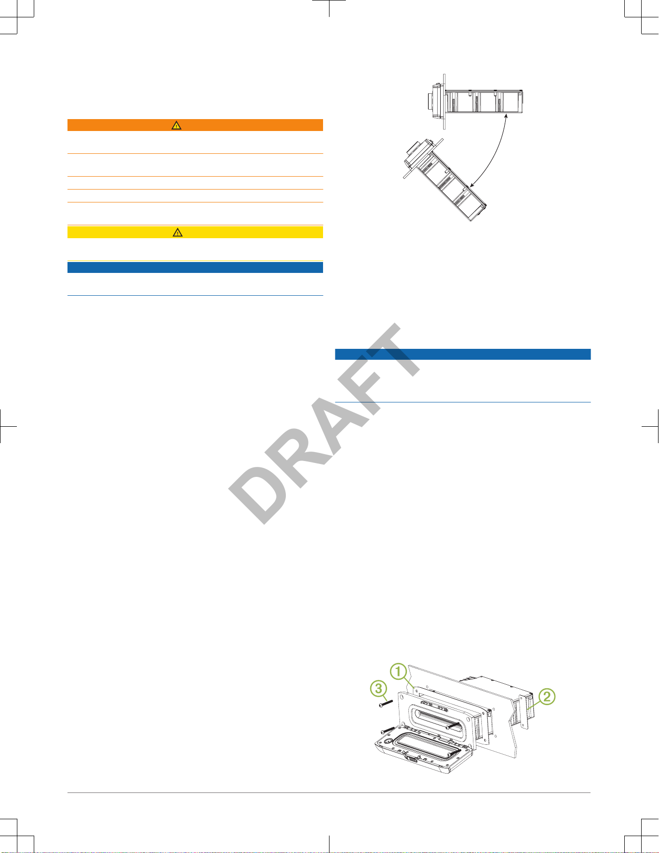
Place the mounting gasket on the back of the stereo À.
2 Installation Instructions
DRAFT

14
If necessary, place the nut plates Á behind the dashboard.
15
Place the stereo in the cutout.
16
Secure the stereo to the mounting surface using the included screws Â.
17
If necessary, secure the back of the stereo with a back strap or brace (not
included).
Connection Considerations
The stereo must be connected to power, to speakers, and to media input
sources to function correctly. You should carefully plan the layout of the
stereo, wired remote, speakers, optional
NMEA 2000® network, and your input
sources before making any connections.
Power and Speaker Wiring Harness Wire Identification
Wire Function Wire Color Notes
Power (+) Yellow This should be connected to a constant 12 Vdc
source capable of supplying 15 A. All 12 V wiring
must be fused at the power source end of your
cable using a 15 A fuse.
Ground (-) Black This should be connected battery negative before
connecting the yellow wire. All accessories
connected to the stereo must share a common
ground location.
Ignition Red This should be connected to a separately switched
12 Vdc connection, such as an ignition bus, to turn
the stereo on and off. If you are not using a
switched 12 Vdc connection, you must connect this
to the same source as the yellow (power) wire.
Amplifier on Blue This is connected only when using an optional
external amplifier.
Telephone Mute Brown When connected to ground and a call is received
on a hands-free mobile phone, this mutes the audio
or switches the input to AUX IN 2 or ARC source
(ARC source is available on the MS-AV755 only).
This is configurable in the Settings menu.
Dim Orange This can be connected to the boat's illumination
wire to dim the stereo screen when the lights are
on.
This must be connected to a wire gauge suitable
for the fuse supplying the circuit it is connected to.
Speaker zone 1
left (+)
White
Speaker zone 1
left (-)
White/black
Speaker zone 1
right (+)
Gray
Speaker zone 1
right (-)
Gray/black
Speaker zone 2
left (+)
Green
Speaker zone 2
left (-)
Green/black
Speaker zone 2
right (+)
Purple
Speaker zone 2
right (-)
Purple/
black
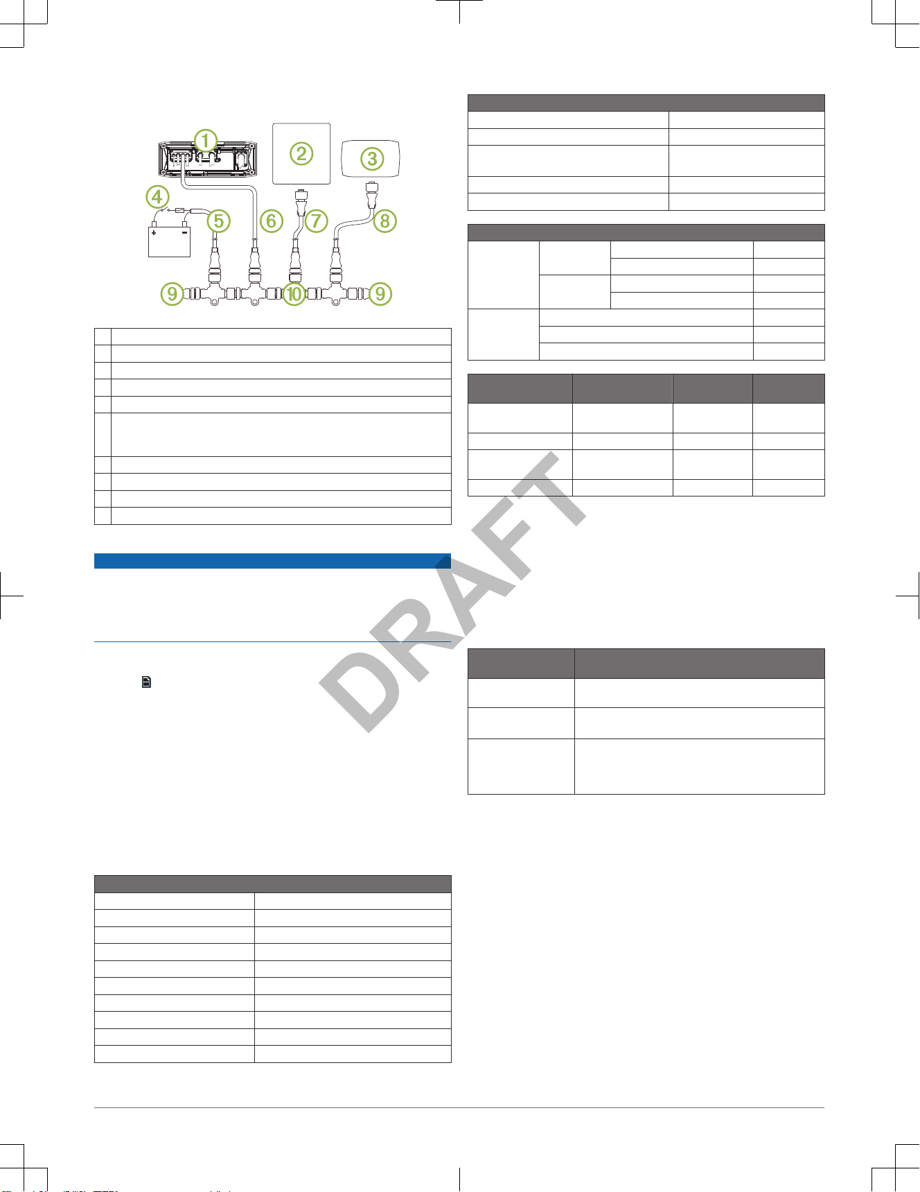
Wiring Harnesses
À
Antenna Motorola-style standard antenna connector
Á
SIRIUSXM TUNER SiriusXM® connector
Â
WIRED REMOTE
NMEA 2000
Connect to a NMEA 2000 network or a FUSION wired
remote
Ã
USB USB-A industry standard
Ä
Video 755 models: HDMI® cable and Ethernet
650 models: composite and component
Å
AUX IN 1, AUX IN 2 Red and white RCA stereo line inputs for sources such as
CD and MP3 players
Æ
Zone connectors Line outputs for speakers and subwoofer amplifiers. 650
models have three zones.
755 models have four zones.
Ç
Power and speaker
wiring harness
See Power and Speaker Wiring Harness Wire
Identification, page 3
Connecting to Power
When connecting the stereo to power, you must connect both power wires.
The yellow power wire should be connected directly to the battery, or
connected using a 15 A isolator switch. This provides power to the stereo and
a constant trickle-power standby feed. The red signal wire should be
connected to the same battery through the ignition or another manual switch to
turn the stereo on and off.
If you are not routing the red wire to the ignition or another manual switch, you
can connect the red wire to the yellow wire, and connect them to the positive
(+) battery terminal.
If it is necessary to extend the yellow power and black ground wires, use
14 AWG (2.08 mm2) wire. For extensions longer than 1 m (3 ft.), use 12 AWG
(3.31 mm²) wire.
If it is necessary to extend the red signal wire, use 22 AWG (0.33 mm2) wire.
1
Route the yellow power À and black ground Á wires to the battery and
route the wiring-harness plug to the stereo.
Do not connect the wiring harness to the stereo until all of the bare wire
connections have been made.
2
Connect the black wire to the negative (-) battery terminal.
Installation Instructions 3
DRAFT

3
Select an option:
•
Connect the yellow wire to the positive (+) battery terminal, and route
the red signal wire  to the ignition or another manual switch Ã.
• Connect the red wire to the yellow wire, and connect them to the
positive (+) battery terminal.
NOTE: You must install a fuse on all power wires near the connection to
the power source.
Enabling Standby Mode
You can set the stereo to enter a low-power standby mode when you hold
so the stereo takes less than the typical 30 seconds to turn on again.
NOTE: When the stereo is set to use the low-power standby mode, it
continues to draw current from the battery. The maximum current draw in
standby mode is listed in the specifications section.
Select > Settings > Standby Mode.
The stereo now enters standby mode when you hold .
Speaker Zones
You can group speakers in one area into speaker zones. This enables you to
control the audio level of the zones individually. For example, you could make
the audio quieter in the cabin and louder on deck.
Zones 1 and 2 are powered by the on-board amplifier. To use the RCA line
outputs and the RCA subwoofer outputs, you must connect external amplifiers.
You can set the balance, volume limit, subwoofer level, and name for each
zone.
Subwoofer Connection Considerations
This stereo supports output to a powered subwoofer for each zone.
The subwoofer outputs are mono line-level signals tied to the corresponding
zone volume.
A splitter is provided to connect this mono output to the stereo input of a
subwoofer amplifier. Additional splitters (not included) are needed for
additional subwoofer connections.
Speaker Amplifier Connection Considerations
This stereo supports output to an external amplifier for each zone.
The zone outputs are stereo line-level signals tied to the zone volume. A
standard RCA cable (not included) is required to connect each zone output to
an external amplifier.
The blue wire from the wiring harness must be connected to each amplifier to
provide a signal to turn on the amplifier with the stereo. If it is necessary to
split or extend this blue signal wire, use 22 AWG (0.33 mm2) wire.
Common Connections to the Stereo
You can connect a variety of additional media inputs and outputs to the stereo,
depending on the stereo model and the devices to which you are connecting.
The connectors are color coded to assist you in making the correct
connections. For example, if your TV has RCA line out ports, you can connect
an RCA cable to the AUX IN 1 or AUX IN 2
connector on the stereo. This table
lists some possible ways to connect devices to the stereo.
NOTE: Not all connectors are available on all stereo models.
Input Stereo Connections
FM/AM radio antenna* Antenna connector
SiriusXM Connect Tuner SIRIUSXM TUNER connector
USB device USB connector or the built-in dock (UD models)
TV with a composite video
connector and RCA audio line
outs
Yellow to COMPOSITE VIDEO (MS-AV650 only)
RCA line outs from TV to AUX IN 1 or AUX IN 2
TV with component connectors
and RCA audio line outs
Three component video connectors to matching
connectors on stereo (MS-AV650 only)
RCA line outs from TV to AUX IN 1 or AUX IN 2
TV with an HDMI connector HDMI cable (MS-AV755 only)
* You should connect a marine, AM/FM, ground-independent antenna.
Ethernet and Wireless Support
You can connect a wireless Ethernet router to the entertainment system to
control the audio with
Wi‑Fi®. You can download free apps from the Apple App
StoreSM for Apple devices. Android™ apps are available through Google Play™.
For more information, see www.fusionentertainment.com.
Audio Return Channel
The Audio Return Channel (ARC) enables you to play the audio from a
television with HDMI technology over the stereo system speakers.
ARC eliminates the need to connect a separate audio cable from the television
to the stereo. Typically, in televisions without ARC, to play the audio from the
television over the stereo system speakers, you would need a separate cable.
With ARC, the HDMI cable sends the television audio to the stereo.
HDMI version 1.4 with ethernet cables support ARC. When planning your
stereo installation, check whether your devices support ARC. Most devices
that support ARC have an ARC label on the HDMI connector that supports
ARC.
Single-Zone System Wiring Example
À
Speakers
Á
Water-tight connection
Three-Zone System Wiring Example
À
Zone 1 speakers, powered from Class D amplifier in stereo
Á
Zone 2 speakers, powered from Class D amplifier in stereo
Â
Zone 3 speakers, powered by an external amplifier connected to the zone 3 line
out
Ã
External amplifier (not included)
Ä
Water-tight connections
Å
Remote on
4 Installation Instructions
DRAFT
NMEA 2000 System Wiring Diagram
À
Stereo
Á
Supported chartplotter MFD
Â
FUSION NRX series wired remote
Ã
In-line switch
Ä
NMEA 2000 power cable
Å
NMEA 2000 cable from the stereo
This can be extended to a maximum length of 6 m (20 ft.) using a
NMEA 2000
cable.
Æ
NMEA 2000 drop cable from the MFD
Ç
NMEA 2000 drop cable from the wired remote
È
NMEA 2000 terminator or backbone cable
É
NMEA 2000 T-connector
Configuring an Optional Wired Remote
NOTICE
The stereo is configured by default to work with a
NMEA 2000 network, and
the NRX Power option should be enabled only when an optional remote is
connected directly to the stereo. Enabling this option when the stereo is
connected to a NMEA 2000 network may damage other devices on the NMEA
2000 network.
If you connect an optional wired NRX remote directly to the stereo, and not
through a NMEA 2000 network , additional configuration is needed.
1
Select > Settings.
2
Select an option:
•
If you connected both your stereo and your optional wired remote to a
NMEA 2000 network, make sure the NRX Power option is not
selected. This enables the optional remote to receive power from the
NMEA 2000 network.
• If you connected the optional wired remote directly to the stereo
through the NMEA 2000 connector, select the NRX Power option. This
enables the stereo to supply power to the optional remote.
Stereo Information
Specifications
General
Weight 0.88 kg (1.96 lb.)
Water resistance IEC 60529 IPX5
Operating temperature range From -5 to 50°C (from 23 to 122°F)
Storage temperature range From -20 to 70°C (from -4 to 158°F)
Compass-safe distance 15 cm (5.9 in.)
Input voltage From 10.8 to 16 Vdc
NMEA 2000 LEN 1 (50 mA)
Bluetooth
®
Class 2
Bluetooth/ANT® frequency From 2,400 to 2,483.5 MHz
Bluetooth/ANT power (max.) 8 dBm EIRP
On-board, Class D Amplifier
Output music power per channel 70 W max. x 4 at 2 ohms
Total output music power 280 W max.
Output power per channel
(14.4 VDC at 10% THD+N)
43W RMS x 4 @ 2 ohms
26W RMS x 4 @ 4 ohms
Line output level (max.) 6 V (peak to peak)
Aux input level (typical) 1 V RMS
Current Consumption
Stereo is off Ignition off Standby Mode = Off < 3 mA
Standby Mode = On < 200 mA
Ignition on Standby Mode = Off < 20 mA
Standby Mode = On < 200 mA
Stereo is on Muted <900 mA
Typical listening volume 2 A
Maximum current draw 15 A
Tuner Europe and
Australasia
USA Japan
FM radio frequency
range
87.5 to 108 MHz 87.5 to 107.9 MHz 76 to 95 MHz
FM frequency step 50 kHz 200 kHz 50 kHz
AM radio frequency
range
522 to 1620 kHz 530 to 1710 kHz 522 to 1620 kHz
AM frequency step 9 kHz 10 kHz 9 kHz
Media Player Compatibility
If you have a UD model, you can use the included adapter cables to connect
popular media players to the internal docking station or the connector on the
back of the stereo. If you have an AV model, you can use the USB cables that
came with your media player to connect the player to the connector on the
back of the stereo.
Only media players with ports on the bottom, not on the sides, fit in the
docking station. Media players larger than 144 × 71 × 13 mm (5.67 × 2.80 ×
0.52 in.) do not fit in the docking station.
Cable Connector in
Dock
Devices
Micro-USB connector Supported media players. See
www.fusionentertainment.com.
Apple 30-pin connector Apple iPhone® 4s.
iPod touch® (5th generation).
Apple Lightning
connector
Apple iPhone 7 Plus, iPhone 7,iPhone 6s Plus, iPhone 6s,
iPhone 6 Plus, iPhone 6, iPhone 5s, iPhone 5c, and iPhone
5.
iPod touch (6th generation) and iPod nano® (7th generation).
You also can connect a FAT32- or NTFS-formatted USB flash drive directly to
the USB port.
Installation Instructions 5
DRAFT
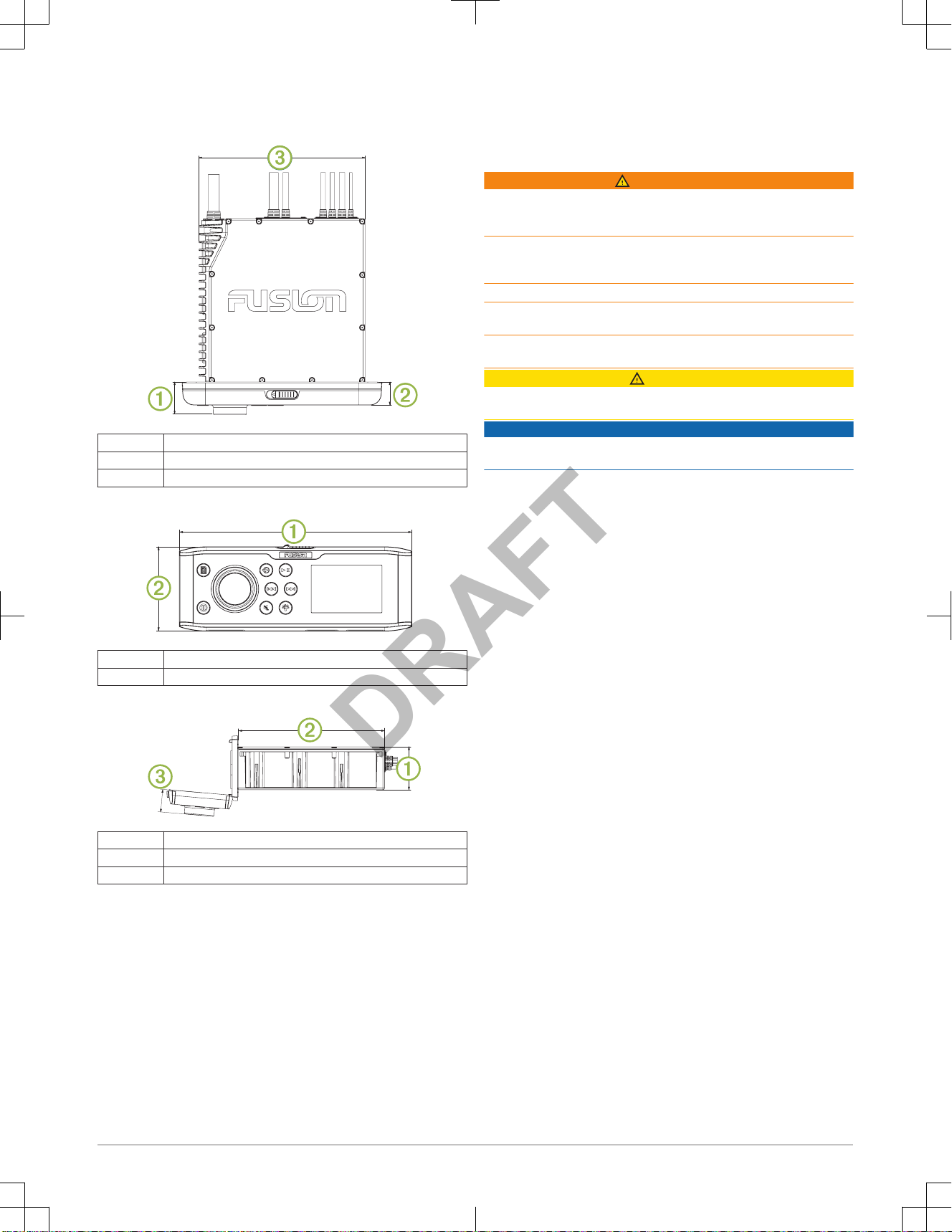
Stereo Dimension Drawings
Top Dimensions
179.94
À
35 mm (1.367 in.)
Á
25 mm (0.97 in.)
Â
180 mm (7.08 in.)
Front Dimensions
À
216 mm (8.50 in.)
Á
78 mm (3.08 in.)
Side Dimensions
À
52 mm (1.37 in.)
Á
177 mm (6.97 in.)
Â
28 mm (1.08 in.)
Software Updates
For best results, you should update the software in all
FUSION devices at the
time of installation to ensure compatibility.
Go to www.fusionentertainment.com/marine to download the latest software.
Software updates and instructions are available on your device product page.
Registering Your FUSION MS-UD/AV650/755
Help us better support you by completing our online registration today.
• Go to www.fusionentertainment.com.
• Keep the original sales receipt, or a photocopy, in a safe place.
Instructions d'installation des appareils
FUSION® MS-UD/AV650/755
Informations importantes relatives à la sécurité
AVERTISSEMENT
Le non-respect de ces avertissements et de ces mises en garde est
susceptible de provoquer des blessures, d'endommager le bateau ou de
dégrader les performances du produit.
Consultez le guide Informations importantes sur le produit et la sécurité inclus
dans l'emballage du produit pour prendre connaissance des avertissements et
autres informations sur le produit.
Cet appareil doit être installé conformément à ces instructions.
Déconnectez l'alimentation du bateau avant de commencer à installer ce
produit.
Avant d'alimenter ce produit en électricité, vérifiez que la mise à la terre est
correcte et qu'elle respecte les instructions de ce guide.
ATTENTION
Portez toujours des lunettes de protection, un équipement antibruit et un
masque anti-poussière lorsque vous percez, coupez ou poncez.
AVIS
Lorsque vous percez ou coupez, commencez toujours par vérifier la nature de
la face opposée de l'élément.
Lisez toutes les instructions d'installation avant de commencer l'installation. Si
vous rencontrez des difficultés durant l'installation, contactez le service
d'assistance produit de
FUSION.
Contenu de l'emballage
• Deux plaques de montage
• Kit de montage
◦ Quatre vis autoperceuses de jauge 8
◦ Quatre vis mécaniques M4
• Faisceaux de câbles d'alimentation et de haut-parleur
• Répartiteur RCA
• Câble micro-USB à USB (modèles UD uniquement)
• Câble Lightning à USB (modèles UD uniquement)
• Apple Câble 30 broches à USB (modèles UD uniquement)
• Télécommande (modèles AV uniquement)
• Deux piles AAA (modèles AV uniquement)
Outils requis
• Tournevis cruciforme
• Perceuse électrique
• Foret (la taille varie en fonction du matériel de montage et des vis utilisées)
• Foreuse rotative ou scie sauteuse
• Mastic d'étanchéité (facultatif)
Considérations relatives au montage
• La chaîne stéréo doit être installée à un emplacement avec suffisamment
d'espace pour ouvrir la trappe, tel qu'illustré sur le modèle.
• L'emplacement d'installation doit permettre une circulation de l'air
suffisante derrière la chaîne stéréo afin d'évacuer la chaleur.
• La chaîne stéréo doit être installée à 45° maximum à partir du plan
horizontal.
6 Instructions d'installation
DRAFT
 Loading...