

Page 1

GPS 175/GNX 375
Pilot's Guide
Page 2

© 2019
Garmin International, Inc., or its subsidiaries
All Rights Reserved
Except as expressly provided herein, no part of this manual may be reproduced, copied,
transmitted, disseminated, downloaded or stored in any storage medium, for any purpose
without the express prior written consent of Garmin. Garmin hereby grants permission to
download a single copy of this manual and of any revision to this manual onto a hard drive or
other electronic storage medium to be viewed and to print one copy of this manual or of any
revision hereto, provided that such electronic or printed copy of this manual or revision must
contain the complete text of this copyright notice and provided further that any unauthorized
commercial distribution of this manual or any revision hereto is strictly prohibited.
This manual reflects the operation of system software v2.00. Some differences in operation
may be observed when comparing the information in this manual to later software versions.
All other marks and logos are property of their respective owners. All rights reserved. Garmin
and SafeTaxi®are registered trademarks of Garmin International or its subsidiaries. Connext™,
Garmin Pilot™, and Smart Airspace™ are trademarks of Garmin International or its
subsidiaries. These trademarks may not be used without the express permission of Garmin.
The Bluetooth
®
word mark and logos are registered trademarks owned by Bluetooth SIG, Inc.
and any use of such marks by Garmin is under license. Other trademarks and trade names are
those of their respective owners.
© 2019 SD
The term Wi-Fi
®
is a registered trademark of SD-3C, LLC. All rights reserved.
®
is a registered trademark of the Wi-Fi Alliance®.
For information regarding the Aviation Limited Warranty, refer to Garmin’s website.
For aviation product support, visit flyGarmin.com.
SOFTWARE LICENSE AGREEMENT
BY USING THE DEVICE, COMPONENT OR SYSTEM MANUFACTURED OR SOLD BY GARMIN
("THE GARMIN PRODUCT"), YOU AGREE TO BE BOUND BY THE TERMS AND CONDITIONS OF
THE FOLLOWING SOFTWARE LICENSE AGREEMENT. PLEASE READ THIS AGREEMENT
CAREFULLY. Garmin Ltd. and its subsidiaries ("Garmin") grants you a limited license to use the
software embedded in the Garmin Product (the "Software") in binary executable form in the
normal operation of the Garmin Product. Title, ownership rights, and intellectual property rights
in and to the Software remain with Garmin and/or its third-party providers. You acknowledge
that the Software is the property of Garmin and/or its third-party providers and is protected
under the United States of America copyright laws and international copyright treaties. You
further acknowledge that the structure, organization, and code of the Software are valuable
trade secrets of Garmin and/or its third-party providers and that the Software in source code
form remains a valuable trade secret of Garmin and/or its third-party providers. You agree not
to reproduce, decompile, disassemble, modify, reverse assemble, reverse engineer, or reduce to
human readable form the Software or any part thereof or create any derivative works based on
the Software. You agree not to export or re-export the Software to any country in violation of
the export control laws of the United States of America.
®
Page 3

Table of Contents
1 SYSTEM AT A GLANCE .....................................................................................................1-1
Overview ...................................................................................................................................................1-2
1.1 Display Layout ........................................................................................... 1-3
1.2 Unit Functions .......................................................................................... 1-4
Pilot Interface ........................................................................................................................................1-5
1.3 Unit Power ................................................................................................ 1-5
1.3.1 Instrument Test .................................................................................. 1-5
1.3.2 Power Off .......................................................................................... 1-5
1.4 SD Card Slot ............................................................................................. 1-6
1.5 Touchscreen ............................................................................................. 1-7
1.5.1 Keys ................................................................................................... 1-8
1.5.2 Menus ................................................................................................ 1-9
1.5.3 Tabs ................................................................................................. 1-10
1.5.4 Keypads ........................................................................................... 1-10
1.6 Control Knobs ........................................................................................ 1-11
1.6.1 Knob Function Indicators .................................................................. 1-11
1.6.2 Screen Captures ............................................................................... 1-12
1.7 Color Conventions .................................................................................. 1-13
Compatible Equipment ..................................................................................................................1-14
1.8 Line Replaceable Units .......................................................................... 1-14
1.8.1 ADC & AHRS .................................................................................... 1-15
1.8.2 Altitude Encoder .............................................................................. 1-15
1.8.3 Connext Services .............................................................................. 1-16
1.8.4 Traffic .............................................................................................. 1-16
2 GET STARTED ........................................................................................................................ 2-1
Databases .................................................................................................................................................2-3
2.1 Database Effective Cycles .......................................................................... 2-4
2.2 Active and Standby Databases .................................................................. 2-5
2.3 Manual Updates ....................................................................................... 2-6
2.3.1 Database Updates Page ...................................................................... 2-6
2.4 Automatic Updates ................................................................................... 2-9
2.5 Database Concierge ................................................................................ 2-10
Connectivity .........................................................................................................................................2-12
2.6 Connext Setup ........................................................................................ 2-12
2.7 Bluetooth Setup ...................................................................................... 2-13
2.7.1 Enabling Bluetooth ........................................................................... 2-13
2.7.2 Managing Paired Devices .................................................................. 2-14
2.7.3 Importing a Flight Plan ..................................................................... 2-14
2.8 Wi-Fi Setup ............................................................................................. 2-15
2.8.1 Connecting to Wi-Fi ......................................................................... 2-15
XPDR ........................................................................................................................................................2-16
2.9 XPDR Setup ............................................................................................ 2-17
2.9.1 Displaying Data ................................................................................ 2-17
2.9.2 Enabling Extended Squitter Transmissions ......................................... 2-17
2.9.3 Assigning a Flight ID ......................................................................... 2-18
2.10 XPDR Modes ......................................................................................... 2-19
2.11 Squawk Code Keys ............................................................................... 2-20
2.11.1 VFR ................................................................................................ 2-20
2.11.2 IDENT ............................................................................................ 2-20
190-02207-02 Rev. 1 GPS 175/GNX 375 Pilot’s Guide i
Page 4

Table of Contents
2.12 Remote Control .................................................................................... 2-22
2.13 XPDR Alert ............................................................................................ 2-22
Pilot Settings ........................................................................................................................................2-23
2.14 CDI Scale .............................................................................................. 2-23
2.14.1 Horizontal Alarm Limits .................................................................. 2-24
2.14.2 CDI On Screen ................................................................................ 2-24
2.15 Airport Runway Criteria ........................................................................ 2-25
2.15.1 Runway Surface ............................................................................. 2-25
2.15.2 Minimum Runway Length .............................................................. 2-25
2.16 Clocks & Timers .................................................................................... 2-26
2.16.1 Timers ............................................................................................ 2-26
2.16.2 Clock ............................................................................................. 2-26
2.17 Page Shortcuts ...................................................................................... 2-27
2.18 Alerts Settings ....................................................................................... 2-28
2.19 Unit Selections ...................................................................................... 2-29
2.20 Display Brightness Control .................................................................... 2-30
2.20.1 Automatic Brightness Control ......................................................... 2-30
2.20.2 Manual Brightness Control ............................................................. 2-30
2.21 Scheduled Messages ............................................................................ 2-31
2.21.1 Message Types ............................................................................... 2-31
2.21.2 Modifying Scheduled Messages ...................................................... 2-31
Status Indications ..............................................................................................................................2-32
2.22 Alert Types ............................................................................................ 2-32
2.22.1 Alert Annunciations ........................................................................ 2-33
2.22.2 Pop-up Alerts ................................................................................. 2-34
2.22.3 Aural Alerts .................................................................................... 2-34
2.23 System Status Page ............................................................................... 2-35
2.24 GPS Status Page .................................................................................... 2-35
2.24.1 Circle of Uncertainty ....................................................................... 2-37
2.24.2 SBAS Providers ............................................................................... 2-38
2.24.3 GPS Status Annunciations .............................................................. 2-38
2.24.4 GPS Alerts ...................................................................................... 2-39
2.25 ADS-B Status Page ................................................................................ 2-40
Logs ...........................................................................................................................................................2-41
2.26 Exporting to SD Card ........................................................................... 2-41
3 NAVIGATION ......................................................................................................................... 3-1
Map ..............................................................................................................................................................3-3
3.1 Map Interactions ....................................................................................... 3-6
3.1.1 Basic Interactions ................................................................................ 3-6
3.1.2 Graphical Flight Plan Editing ............................................................... 3-8
3.2 Map Setup .............................................................................................. 3-12
3.2.1 Configure User Fields ....................................................................... 3-13
3.2.2 Map Orientation ............................................................................... 3-14
3.2.3 North Up Above ............................................................................... 3-15
3.2.4 Visual Approach ............................................................................... 3-15
3.2.5 TOPO Scale ...................................................................................... 3-15
3.2.6 Range Ring ....................................................................................... 3-16
3.2.7 Track Vector ..................................................................................... 3-16
3.2.8 Ahead View ..................................................................................... 3-16
ii GPS 175/GNX 375 Pilot’s Guide 190-02207-02 Rev. 1
Page 5

Table of Contents
3.2.9 Map Detail ....................................................................................... 3-17
3.3 Map Overlays .......................................................................................... 3-19
3.3.1 Overlay Controls ............................................................................... 3-19
3.3.2 Overlay Status Icons ......................................................................... 3-22
3.3.3 Smart Airspace ................................................................................. 3-23
3.3.4 SafeTaxi ........................................................................................... 3-24
Active Flight Plan ..............................................................................................................................3-26
3.4 Edit Data Fields ....................................................................................... 3-28
3.5 Collapse All Airways ................................................................................ 3-28
3.6 Parallel Track ........................................................................................... 3-29
3.7 Flight Plan Catalog .................................................................................. 3-30
3.7.1 Delete a Flight Plan ........................................................................... 3-31
3.8 Creating a Flight Plan .............................................................................. 3-32
3.9 Waypoint Options ................................................................................... 3-33
3.10 Active Flight Plan Map Overlay .............................................................. 3-34
3.11 GPS NAV Status Indicator Key ............................................................... 3-35
Direct To .................................................................................................................................................3-36
Waypoints ..............................................................................................................................................3-39
3.12 Waypoint Information ........................................................................... 3-39
3.13 Waypoint Selection ............................................................................... 3-42
3.13.1 Waypoint Autofill ........................................................................... 3-42
3.13.2 Search Tabs .................................................................................... 3-43
3.14 Create User Waypoints ......................................................................... 3-45
3.14.1 Define Waypoint Criteria ................................................................ 3-46
3.14.2 Edit an Existing User Waypoint ....................................................... 3-48
3.14.3 Import User Waypoints ................................................................... 3-48
3.15 Nearest ................................................................................................. 3-49
Procedures ............................................................................................................................................3-51
3.16 Basic Operations ................................................................................... 3-52
3.16.1 GPS Flight Phase Annunciations ...................................................... 3-52
4 PLANNING .............................................................................................................................. 4-1
Vertical Calculator ..............................................................................................................................4-3
4.1 VCALC Page ............................................................................................. 4-3
4.2 VCALC Setup ............................................................................................ 4-4
Fuel Planning ..........................................................................................................................................4-5
4.3 Fuel Planning Page .................................................................................... 4-5
4.3.1 Fuel Planning Modes .......................................................................... 4-5
4.3.2 Computing Fuel Statistics ................................................................... 4-7
DALT/TAS/Wind Calculator ............................................................................................................4-8
4.4 DALT/TAS/Wind Page ................................................................................ 4-8
4.4.1 Editing Input Data .............................................................................. 4-8
4.4.2 Computing DALT/TAS/Wind Statistics ............................................... 4-10
RAIM Prediction .................................................................................................................................4-11
4.5 RAIM Prediction Page .............................................................................. 4-11
4.5.1 Calculating RAIM Status ................................................................... 4-12
4.5.2 RAIM Status Indications .................................................................... 4-12
5 HAZARD AWARENESS .....................................................................................................5-1
Weather Awareness ............................................................................................................................5-3
5.1 Data Transmission Limitations ................................................................... 5-3
190-02207-02 Rev. 1 GPS 175/GNX 375 Pilot’s Guide iii
Page 6

Table of Contents
5.1.1 Line of Sight Reception ....................................................................... 5-3
5.1.2 Per FAA TSO-C157b ........................................................................... 5-4
5.1.3 NOTAM 30-Day Limitation ................................................................. 5-4
5.2 Weather Display ........................................................................................ 5-5
5.3 Weather Setup .......................................................................................... 5-7
5.4 Weather Products ..................................................................................... 5-8
5.4.1 Product Age ....................................................................................... 5-9
5.4.2 Legends ........................................................................................... 5-10
5.4.3 FIS-B NEXRAD .................................................................................. 5-11
5.4.4 METARs and TAFs ............................................................................ 5-13
5.4.5 AIRMETS .......................................................................................... 5-14
5.4.6 SIGMETS .......................................................................................... 5-15
5.4.7 PIREPs .............................................................................................. 5-15
5.4.8 Winds Aloft ...................................................................................... 5-16
5.4.9 TFRs ................................................................................................. 5-16
5.5 Raw Text Reports .................................................................................... 5-17
5.6 FIS-B Ground Reception Status ................................................................ 5-17
Traffic Awareness .............................................................................................................................5-18
5.7 Traffic Applications ................................................................................. 5-18
5.8 Traffic Display ......................................................................................... 5-19
5.9 Traffic Interactions .................................................................................. 5-22
5.10 Traffic Setup ......................................................................................... 5-23
5.10.1 Traffic Test ..................................................................................... 5-24
5.10.2 Motion Vectors .............................................................................. 5-24
5.10.3 Altitude Filtering ............................................................................. 5-25
5.11 Status Annunciations ............................................................................ 5-25
5.12 Traffic Alerting ...................................................................................... 5-26
Terrain Awareness ............................................................................................................................5-27
5.13 Terrain Configurations .......................................................................... 5-27
5.13.1 GPS Altitude for Terrain .................................................................. 5-27
5.14 Database Limitations ............................................................................. 5-29
5.15 Terrain Display ...................................................................................... 5-30
5.16 Terrain Setup ........................................................................................ 5-32
5.17 Terrain Proximity ................................................................................... 5-33
5.17.1 Terrain Elevation Depictions ............................................................ 5-34
5.17.2 Obstacle Elevation Depictions ......................................................... 5-35
5.18 Terrain Alerting ..................................................................................... 5-37
5.18.1 Alert Types ..................................................................................... 5-37
5.18.2 Alerting Thresholds ........................................................................ 5-38
5.18.3 Inhibiting PDA & Terrain-FLTA Alerts ............................................... 5-39
5.18.4 PDA & Terrain-FLTA Alerts .............................................................. 5-40
6 MESSAGES .............................................................................................................................. 6-1
Advisory Messages ..............................................................................................................................6-2
6.1 Message Key ............................................................................................. 6-2
6.2 Airspace Advisories ................................................................................... 6-3
6.3 Database Advisories .................................................................................. 6-4
6.4 Flight Plan Advisories ................................................................................ 6-5
6.5 GPS/WAAS Advisories ............................................................................... 6-6
6.6 Navigation Advisories ................................................................................ 6-8
iv GPS 175/GNX 375 Pilot’s Guide 190-02207-02 Rev. 1
Page 7

Table of Contents
6.7 System Hardware Advisories ..................................................................... 6-9
6.8 Terrain Advisories .................................................................................... 6-11
6.9 Traffic System Advisories ......................................................................... 6-12
6.10 VCALC Advisories ................................................................................. 6-13
6.11 Waypoint Advisories ............................................................................. 6-13
7 QUALIFICATION .................................................................................................................. 7-1
7.1 Glove Qualification ................................................................................... 7-1
8 GLOSSARY ............................................................................................................................... 8-1
190-02207-02 Rev. 1 GPS 175/GNX 375 Pilot’s Guide v
Page 8

INTENTIONALLY LEFT BLANK
vi GPS 175/GNX 375 Pilot’s Guide 190-02207-02 Rev. 1
Page 9

Warnings, Cautions, and Notes
WARNING
DO NOT USE TERRAIN AVOIDANCE DISPLAYS AS THE SOLE SOURCE OF INFORMATION
FOR MAINTAINING SEPARATION FROM TERRAIN AND OBSTACLES. GARMIN OBTAINS
TERRAIN AND OBSTACLE DATA FROM THIRD PARTY SOURCES AND CANNOT
INDEPENDENTLY VERIFY THE ACCURACY OF THE INFORMATION.
WARNING
DO NOT RELY SOLELY UPON TERRAIN PROXIMITY DATA FOR TERRAIN AVOIDANCE.
TERRAIN PROXIMITY IS NOT A CERTIFIED TERRAIN AWARENESS SYSTEM. IT IS AN AID
TO SITUATIONAL AWARENESS ONLY. USING TERRAIN PROXIMITY DATA DOES NOT
UNDER ANY CIRCUMSTANCES OR CONDITIONS RELIEVE THE PILOT’S RESPONSIBILITY
TO SEE AND AVOID TERRAIN OR OBSTACLES.
WARNING
ALWAYS REFER TO CURRENT AERONAUTICAL CHARTS AND NOTAMS FOR
VERIFICATION OF DISPLAYED AERONAUTICAL INFORMATION. DISPLAYED
AERONAUTICAL DATA MAY NOT INCORPORATE THE LATEST NOTAM INFORMATION.
WARNING
NEVER USE GPS ALTITUDE FOR VERTICAL NAVIGATION. THE ALTITUDE CALCULATED
BY GPS RECEIVERS IS GEOMETRIC HEIGHT ABOVE MEAN SEA LEVEL AND COULD VARY
SIGNIFICANTLY FROM THE ALTITUDE DISPLAYED BY PRESSURE ALTIMETERS (E.G., THE
OUTPUT FROM THE GDC 74A/B AIR DATA COMPUTER) OR OTHER ALTIMETERS IN THE
AIRCRAFT. ALWAYS REFER TO THE PRESSURE ALTIMETERS IN THE AIRCRAFT FOR
CURRENT PRESSURE ALTITUDE.
WARNING
NEVER USE EXPIRED DATABASES. UPDATE DATABASES REGULARLY TO ENSURE
CURRENCY. USE OUT OF DATE DATABASE INFORMATION AT YOUR OWN RISK.
WARNING
NEVER USE BASEMAP INFORMATION (LAND AND WATER DATA) AS THE SOLE MEANS
OF NAVIGATION. BASEMAP DATA IS INTENDED ONLY TO SUPPLEMENT OTHER
APPROVED NAVIGATION DATA SOURCES AND SHOULD BE CONSIDERED ONLY AN AID
TO ENHANCE SITUATIONAL AWARENESS.
WARNING
DO NOT RELY SOLELY UPON THE DISPLAY OF TRAFFIC INFORMATION TO
ACCURATELY DEPICT ALL OF THE TRAFFIC WITHIN RANGE OF THE AIRCRAFT. DUE TO
LACK OF EQUIPMENT, POOR SIGNAL RECEPTION, AND/OR INACCURATE
INFORMATION FROM AIRCRAFT OR GROUND STATIONS, TRAFFIC MAY BE PRESENT
THAT IS NOT REPRESENTED ON THE DISPLAY.
190-02207-02 Rev. 1 GPS 175/GNX 375 Pilot’s Guide
vii
Page 10

Warnings, Cautions, and Notes
WARNING
NEVER USE DATALINK WEATHER INFORMATION FOR MANEUVERING IN, NEAR, OR
AROUND AREAS OF HAZARDOUS WEATHER. INFORMATION CONTAINED WITHIN
DATALINK WEATHER PRODUCTS MAY NOT ACCURATELY DEPICT CURRENT WEATHER
CONDITIONS.
WARNING
DO NOT USE THE INDICATED DATALINK WEATHER PRODUCT AGE TO DETERMINE
THE AGE OF THE WEATHER INFORMATION SHOWN BY THE DATALINK WEATHER
PRODUCT. DUE TO TIME DELAYS INHERENT IN GATHERING AND PROCESSING
WEATHER DATA FOR DATALINK TRANSMISSION, THE WEATHER INFORMATION
SHOWN BY THE DATALINK WEATHER PRODUCT MAY BE OLDER THAN THE
INDICATED WEATHER PRODUCT AGE.
WARNING
ALWAYS REFER TO CURRENT AERONAUTICAL CHARTS FOR APPROPRIATE MINIMUM
CLEARANCE ALTITUDES. THE DISPLAYED MSAs ARE ONLY ADVISORY IN NATURE AND
SHOULD NOT BE RELIED UPON AS THE SOLE SOURCE OF OBSTACLE AND TERRAIN
AVOIDANCE INFORMATION.
WARNING
DO NOT USE GPS TO NAVIGATE TO ANY ACTIVE WAYPOINT IDENTIFIED AS A “NON
WGS84 WPT” BY A SYSTEM MESSAGE. “NON WGS84 WPT” WAYPOINTS ARE DERIVED
FROM AN UNKNOWN MAP REFERENCE DATUM THAT MAY BE INCOMPATIBLE WITH
THE MAP REFERENCE DATUM USED BY GPS (KNOWN AS WGS84) AND MAY BE
POSITIONED IN ERROR AS DISPLAYED.
viii
WARNING
DO NOT RELY SOLELY UPON THE DISPLAY OF TRAFFIC INFORMATION FOR COLLISION
AVOIDANCE MANEUVERING. THE TRAFFIC DISPLAY DOES NOT PROVIDE COLLISION
AVOIDANCE RESOLUTION ADVISORIES AND DOES NOT UNDER ANY CIRCUMSTANCES
OR CONDITIONS RELIEVE THE PILOT’S RESPONSIBILITY TO SEE AND AVOID OTHER
AIRCRAFT.
WARNING
DO NOT RELY ON THE ACCURACY OF ATTITUDE AND HEADING INDICATIONS IN
GEOGRAPHIC AREAS WHERE VARIATION IN THE EARTH’S MAGNETIC FIELD EXISTS.
THIS INCLUDES: NORTH OF 72° NORTH LATITUDE AT ALL LONGITUDES; SOUTH OF 70°
SOUTH LATITUDE AT ALL LONGITUDES; NORTH OF 65° NORTH LATITUDE BETWEEN
LONGITUDE 75° W. AND 120° W. (NORTHERN CANADA); NORTH OF 70° NORTH
LATITUDE BETWEEN LONGITUDE 70° W. AND 128° W. (NORTHERN CANADA); NORTH
OF 70° NORTH LATITUDE BETWEEN LONGITUDE 85° E. AND 114° E. (NORTHERN
RUSSIA); SOUTH OF 55° SOUTH LATITUDE BETWEEN LONGITUDE 120° E. AND 165° E.
(REGION SOUTH OF AUSTRALIA AND NEW ZEALAND).
GPS 175/GNX 375 Pilot’s Guide 190-02207-02 Rev. 1
Page 11

Warnings, Cautions, and Notes
WARNING
DO NOT RELY SOLELY UPON DATALINK SERVICES TO PROVIDE TFR INFORMATION.
ALWAYS CONFIRM TFR INFORMATION THROUGH OFFICIAL SOURCES SUCH AS
FLIGHT SERVICE STATIONS OR AIR TRAFFIC CONTROL.
WARNING
DO NOT LEARN OPERATIONAL PROCEDURES IN THE AIR. FOR SAFETY REASONS,
THOROUGHLY PRACTICE BASIC OPERATION ON THE GROUND BEFORE ACTUAL USE.
WARNING
REVIEW AND UNDERSTAND ALL ASPECTS OF THIS PILOT’S GUIDE. DOING SO REDUCES
THE RISK OF UNSAFE OPERATION.
WARNING
ALWAYS RESOLVE ANY DISCREPANCIES BETWEEN THE DISPLAY AND OTHER
NAVIGATION SOURCES WHEN THEY OCCUR. DURING FLIGHT OPERATIONS,
COMPARE DISPLAY INDICATIONS TO INFORMATION FROM OTHER NAVAIDS, VISUAL
SIGHTINGS, CHARTS, AND OTHER AVAILABLE SOURCES BEFORE CONTINUING
NAVIGATION.
CAUTION
DO NOT CLEAN DISPLAY SURFACES WITH ABRASIVE CLOTHS OR CLEANERS
CONTAINING AMMONIA. THEY WILL HARM THE ANTI-REFLECTIVE COATING.
CAUTION
ENSURE THAT ANY UNIT REPAIRS ARE MADE BY AN AUTHORIZED GARMIN
SERVICE CENTER. UNAUTHORIZED REPAIRS OR MODIFICATIONS COULD VOID
BOTH THE WARRANTY AND AFFECT THE AIRWORTHINESS OF THE AIRCRAFT.
NOTE
All visual depictions contained within this document, including screen images
of the system panel and displays, are subject to change and may not reflect
the most current system and aviation databases. Depictions of equipment
may differ slightly from the actual equipment.
NOTE
The United States government operates the Global Positioning System and is
solely responsible for its accuracy and maintenance. The GPS system is
subject to changes which could affect the accuracy and performance of all
GPS equipment. Portions of the system utilize GPS as a precision electronic
NAVAID. Therefore, as with all NAVAIDs, information presented by the
system can be misused or misinterpreted and, therefore, become unsafe.
190-02207-02 Rev. 1 GPS 175/GNX 375 Pilot’s Guide
ix
Page 12

Warnings, Cautions, and Notes
NOTE
This device complies with part 15 of the FCC Rules. Operation is subject to
the following two conditions: (1) this device may not cause harmful
interference, and (2) this device must accept any interference received,
including interference that may cause undesired operation.
NOTE
Interference from GPS repeaters operating inside nearby hangars can cause
an intermittent loss of attitude and heading displays while the aircraft is on
the ground. Moving the aircraft more than 100 yards away from the source
of the interference should alleviate the condition.
NOTE
Use of polarized eye wear may cause the flight displays to appear dim or
blank.
NOTE
This product, its packaging, and its components contain chemicals known to
the State of California to cause cancer, birth defects, or reproductive harm.
This notice is being provided in accordance with California’s Proposition 65.
If you have any questions or would like additional information, please refer
to our website at www.garmin.com/prop65.
NOTE
Operating the system in the vicinity of metal buildings, metal structures, or
electromagnetic fields can cause sensor differences that may result in
nuisance miscompare annunciations during start up, shut down, or while
taxiing. If one or more of the sensed values are unavailable, the annunciation
indicates no comparison is possible.
NOTE
The system responds to a terminal procedure based on data coded within
that procedure in the Navigation Database. Differences in system operation
may be observed among similar types of procedures due to differences in the
Navigation Database coding specific to each procedure.
NOTE
Do not use SafeTaxi functions as the basis for ground maneuvering. SafeTaxi
functions do not comply with the requirements of AC 120-76C and are not
qualified for use as an airport moving map display. SafeTaxi is to be used for
orientation purposes only.
x GPS 175/GNX 375 Pilot’s Guide 190-02207-02 Rev. 1
Page 13

Warnings, Cautions, and Notes
NOTE
The FAA has asked Garmin to remind pilots who fly with Garmin
database-dependent avionics of the following:
• It is the pilot’s responsibility to remain familiar with all FAA regulatory and
advisory guidance and information related to the use of databases in the
National Airspace System.
• Garmin equipment will only recognize and use databases that are obtained
from Garmin or Jeppesen. Databases obtained from Garmin or Jeppesen that
have a Type 2 LOA from the FAA are assured compliance with all data quality
requirements (DQRs). A copy of the Type 2 LOA is available for each
applicable database and can be viewed at flyGarmin.com by selecting
“Aviation Database Declarations.”
• Use of a current Garmin or Jeppesen database in
is required for compliance with established FAA regulatory guidance, but
does not constitute authorization to fly any and all terminal procedures that
may be presented by the system. It is the pilot’s responsibility to operate in
accordance with established AFM(S) and regulatory guidance or limitations
as applicable to the pilot, the aircraft, and installed equipment.
your Garmin equipment
NOTE
The pilot/operator must review and be familiar with Garmin’s database
exclusion list as discussed in SAIB CE-14-04 to determine what data may be
incomplete. The database exclusion list can be viewed at flyGarmin.com by
selecting “Database Exclusions List.”
NOTE
The pilot/operator must have access to Garmin and Jeppesen database alerts
and consider their impact on the intended aircraft operation. The database
alerts can be viewed at flyGarmin.com by selecting “Aviation Database
Alerts.”
NOTE
If the pilot/operator wants or needs to adjust the database, contact Garmin
Product Support.
NOTE
Garmin requests the flight crew report any observed discrepancies related to
database information. These discrepancies could come in the form of an
incorrect procedure; incorrectly identified terrain, obstacles and fixes; or any
other displayed item used for navigation or communication in the air or on
the ground. Visit flyGarmin.com and select “Aviation Data Error Report.”
190-02207-02 Rev. 1 GPS 175/GNX 375 Pilot’s Guide xi
Page 14

Compliance
NOTE
The navigation databases used in Garmin navigation systems contain Special
Procedures. Prior to flying these procedures, pilots must have specific FAA
authorization, training, and possession of the corresponding current, and
legitimately-sourced chart (approach plate, etc.). Inclusion of the Special
Procedure in the navigation database DOES NOT imply specific FAA
authorization to fly the procedure.
AC 90-100A Statement of Compliance
The Garmin navigational unit meets the performance and functional requirements of
FAA Advisory Circular (AC) 90-100A, U.S. Terminal and En Route Area Navigation
(RNAV) Operations.
xii
GPS 175/GNX 375 Pilot’s Guide 190-02207-02 Rev. 1
Page 15

Record of Revision
REVISION DATE CHANGE DESCRIPTION
1 02/07/19 Experimental Release.
Layout
About This Guide
SECTION TITLE
1
2
3
4
5
6
7
8
System at a Glance
Get Started
Navigation
Planning
Hazard Awareness
Messages
Qualification
Glossary
The design and layout of this guide is
intended to provide clear, concise
sections written in the logical order
of a pilot’s flight instrument and
systems scan.
Electronic Document Features
Versions of this guide are saved in Adobe Acrobat and are available for download at:
garmin.com/manuals
190-02207-02 Rev. 1 GPS 175/GNX 375 Pilot’s Guide
xiii
Page 16

Reference Documentation
Reference Manuals
DOCUMENT P/N
N/A N/A
Reference Websites
WEBSITE ADDRESS
Aviation Limited Warranty https://www.garmin.com/en-US/legal/aviation-limited-warranty
Database Concierge
ADS-B Academy https://www.garmin.com/us/intheair/ads-b
Connext http://www.garmin.com/connext
Go to http://www.flygarmin.com/support and select
Database Management.
xiv
GPS 175/GNX 375 Pilot’s Guide 190-02207-02 Rev. 1
Page 17

System at a Glance
1 System at a Glance
OVERVIEW
1.1 Display Layout .......................................................................................1-3
1.2 Unit Functions ......................................................................................1-4
PILOT INTERFACE
1.3 Unit Power ............................................................................................1-5
1.3.1 Instrument Test ..............................................................................1-5
1.3.2 Power Off.......................................................................................1-5
1.4 SD Card Slot..........................................................................................1-6
1.5 Touchscreen ..........................................................................................1-7
1.5.1 Keys ...............................................................................................1-8
1.5.2 Menus............................................................................................1-9
1.5.3 Tabs .............................................................................................1-10
1.5.4 Keypads .......................................................................................1-10
1.6 Control Knobs .....................................................................................1-11
1.6.1 Knob Function Indicators ..............................................................1-11
1.6.2 Screen Captures ...........................................................................1-12
1.7 Color Conventions...............................................................................1-13
COMPATIBLE EQUIPMENT
1.8 Line Replaceable Units .......................................................................1-14
1.8.1 ADC & AHRS ................................................................................1-15
1.8.2 Altitude Encoder...........................................................................1-15
1.8.3 Connext Services ..........................................................................1-16
1.8.4 Traffic...........................................................................................1-16
190-02207-02 Rev. 1 GPS 175/GNX 375 Pilot’s Guide 1-1
Page 18

System at a Glance
Overview
The GPS 175 and GNX 375 are the first 2” by 6.25” panel mount navigators to
employ full color capacitive touchscreen technology.
The GPS 175 is a TSO-C146e compliant GPS/WAAS navigator with en route,
terminal, and precision/non-precision approach capabilities. The GNX 375 combines
the functionality of the GPS 175 with a TSO-C112e (Level 2els, Class 1) compliant
mode S transponder.
Each unit is Bluetooth compatible, providing flight plan, traffic, weather, and
position data to an available portable electronic device.
GPS 175 NAVIGATOR
• TSO-C146e compliant GPS/WAAS navigator and internal GPS source
• TSO-C195b (Class B1, B3, B5, B7) compliant with an active ADS-B In source
• Certified compatible with ADS-B Out 2020 mandate
GNX 375 NAVIGATOR WITH TRANSPONDER
• TSO-C88b compliant automatic pressure altitude reporting equipment
• TSO-C146e compliant GPS/WAAS navigator
• TSO-C112e (Level 2els, Class 1) compliant mode S transponder
• TSO-C154c (Class A1S) compliant 1090/UAT receiver
• TSO-C157b (Class 1) compliant FIS-B equipment uplink
• TSO-C166b compliant ADS-B Out 1090 MHz extended squitter
• TSO-C195b (Class B1, B3, B5, B7, C1, C2, C3, C5, C7) compliant with an
active ADS-B In source
1-2 GPS 175/GNX 375 Pilot’s Guide 190-02207-02 Rev. 1
Page 19

1.1 Display Layout
1
Bezel
Includes the power key, mechanical knobs, photocell, and SD card slot.
1
Ledges provide hand stability when performing data entry and making
selections.
Touchscreen
2
Multi-touch color display provides controls for unit operation.
Photocell
3
Measures cockpit ambient light level to automatically adjust display
brightness for day and night.
System at a Glance
2
3
4
5
6
SD Card Slot
Interface for loading database, exporting log files, and updating
4
software. Compatibility with Flight Stream 510 allows wireless database
transfer from the Garmin Pilot app via Database Concierge.
Power/Home Key
5
Powers the unit on or off and provides direct access to the Home page.
Inner & Outer Knobs
6
Multipurpose dual concentric knob allows data entry, list scrolling, map
range control, and page navigation.
190-02207-02 Rev. 1 GPS 175/GNX 375 Pilot’s Guide 1-3
Page 20

System at a Glance
1.2 Unit Functions
GPS 175 NAVIGATOR
• Moving Map
• Traffic [1]
• Terrain
• Flight Plan
• Graphical Flight Planning
• FIS-B Weather Display [1] [2]
• Waypoint Information
• Terrain Avoidance
• System Advisories
• Scheduled Messages
• Clock
• CDI
• Internal GPS Receiver
• Built-in Bluetooth
• ADS-B In Traffic Display [1] [2]
• Database Concierge Access [3]
GNX 375 NAVIGATOR
W/TRANSPONDER
• Moving Map
• Traffic
• Terrain
• Flight Plan
• Graphical Flight Planning
• FIS-B Weather Receiver & Display[2]
• Waypoint Information
• Terrain Avoidance
• System Advisories
• Scheduled Messages
• Clock
• CDI
• Internal GPS Receiver
• Built-in Bluetooth
• ADS-B In Traffic Receiver & Display
[2]
• ADS-B Out on 1090 MHz Extended
Squitter
• Mode S Transponder
• Database Concierge Access [3]
[1] Function availability dependent upon aircraft interfaces or enablement.
[2] ADS-B In via 1090 MHz (traffic) and 978 MHz UAT (traffic and weather).
[3] Requires Wi-Fi connection via Flight Stream 510.
1-4 GPS 175/GNX 375 Pilot’s Guide 190-02207-02 Rev. 1
Page 21

System at a Glance
Pilot Interface
1.3 Unit Power
The unit receives power directly from the aircraft’s electrical system. Upon power-up,
the bezel key backlight momentarily illuminates. System failure annunciations
typically disappear within the first 30 seconds after power-up.
The start-up screen presents the unit software versions, the name and status of all
installed databases, and the Database Updates page access key. These features are
available only at power up.
Tapping Continue advances to the Instrument Test page.
If an instrument remains flagged after one minute, check the status of the
associated LRU, then contact a Garmin dealer for support.
1.3.1 Instrument Test
To ensure safe operation, continuous built-in test features exercise the unit’s
processor, memory, external inputs, and outputs. The Instrument Test page displays
the results of all external equipment checks performed by the unit.
Review this list to ensure that all
CDI outputs and other displayed
data are correct for the
connected equipment.
1.3.2 Power Off
WARNING
NEVER ATTEMPT TO POWER OFF THE UNIT WHILE AIRBORNE UNLESS
OPERATIONAL PROCEDURES DICTATE.
Pushing and holding the Power key for
0.5 seconds initiates the power off sequence.
Shutdown occurs once the timer reaches zero.
Power off annunciation temporarily replaces
the knob function indicator.
190-02207-02 Rev. 1 GPS 175/GNX 375 Pilot’s Guide 1-5
Page 22

System at a Glance
1.4 SD Card Slot
NOTE
Do not remove or insert an SD card while in flight. Always verify the system
is powered off before inserting or removing an SD card.
The navigator requires an SD card for the following tasks.
• Exporting data logs • Saving system configurations
• Capturing screen images • Enabling Flight Stream connectivity
• Upgrading software • Updating databases
INSERT AN SD CARD
When inserting an SD card:
1. Verify the slot is empty.
2. Hold card such that label faces left edge of display screen.
3. Ensure back edge of card is flush with display bezel after insertion.
EJECT AN SD CARD
Release the spring latch by pressing lightly on the back edge of card.
1-6 GPS 175/GNX 375 Pilot’s Guide 190-02207-02 Rev. 1
Page 23

1.5 Touchscreen
System at a Glance
GESTURES
TAP
TAP AND HOLD
SWIPE
FLICK
Touching the screen briefly with a single finger.
Use this gesture for:
• Opening a page or menu
• Activating a command key or data entry field
• Displaying map feature information
• Selecting an option within an application
Certain momentary controls (e.g., directional arrow
keys) provide a secondary tap and hold function.
Tap the key and hold your finger in place until the
desired action occurs.
Use this gesture for:
• Scrolling with arrow keys
• Increasing/decreasing values continuously
A smooth motion that involves touching an object,
then sliding your finger across the screen and then
lifting up.
Use this gesture for:
• Accessing multiple panes (right or left swipes)
• Viewing and scrolling lists
• Panning across a map display
Swiping the screen in a quick upward or downward
motion. Information moves at a fast speed, then slows
to a stop.
Use this gesture for:
• Scrolling an item list
PINCH & STRETCH
190-02207-02 Rev. 1 GPS 175/GNX 375 Pilot’s Guide 1-7
Touch any map with two fingers at the same time,
then bring the fingers close together (pinch) or spread
them apart (stretch). Just remember: stretch to zoom
in and pinch to zoom out.
Use this gesture for:
• Magnifying map features
Page 24

System at a Glance
1.5.1 Keys
COMMON COMMANDS
Open the system messages
list. A flashing icon indicates
unread messages.
Open a context menu. Input a specified value.
Return to the previous
page.
Cancel an active function
without inputting data.
Select the corresponding
item (e.g., database
update). A checkmark
confirms selection.
FUNCTION KEYS
Toggle keys turn a specific function on or off.
The current state of the function is indicated
below the key label.
On
Off
PAGE ICONS
Tapping one of these icons opens the corresponding page. Menu pages provide
additional icons for accessing functions on subpages.
1-8 GPS 175/GNX 375 Pilot’s Guide 190-02207-02 Rev. 1
Page 25

System at a Glance
1.5.2 Menus
Menus group related controls into an expandable pane, allowing access to multiple
functions on a single page. Depending on the number of available functions, a menu
may comprise more than one pane.
Multiple panes are accessible by
way of swipe or inner knob turn.
Active Pane
An indicator at the bottom of the menu shows
which pane is active.
POP-UP MENUS
Pop-up menus open to the default
or previously selected value.
Underlying Page Hidden
Default or Current Setting
LISTS
Scrollable lists group control keys related to a single function (e.g., FIS-B Weather).
When scrolling, all keys in the list are inactive.
Toggle keys either enable or disable list items.
In some cases, Settings or Range keys provide
access to selectable setting options.
Scroll Bar
190-02207-02 Rev. 1 GPS 175/GNX 375 Pilot’s Guide 1-9
Page 26

System at a Glance
1.5.3 Tabs
Tabs group information into individual panes. Content includes scrolling lists, data
fields, function keys, or a combination of controls.
Tabs are located along the left and right sides of a pane.
Active
Tabs
Inactive
Inactive
Tabs
Tabs
1.5.4 Keypads
The navigator employs multiple keypad types to serve specific settings and functions.
NUMERIC
Numeric keypads
open on a single
pane.
ALPHANUMERIC
Alphanumeric keypads comprise multiple keysets that are accessible by way of swipe
or key selection.
Selectable Keysets
An indicator shows which keyset is active.
Keys a through m are active by default.
Active Keyset
1-10 GPS 175/GNX 375 Pilot’s Guide 190-02207-02 Rev. 1
Page 27

1.6 Control Knobs
Inner and outer control knobs offer an alternative method for
selecting and modifying data without the use of touch keys.
Outer Inner
KNOB FUNCTIONS
• Selecting reference controls
Outer Knob
Inner Knob
(Turn)
• Selecting a page shortcut
• Cursor placement and initial field/page selections
• Moving cursor forward or backward within data field
• Zooming
• Selecting reference values
• Inputting data
• Modifying individual characters in data entry field
System at a Glance
Inner Knob
(Push)
• Entering current or specified numerical value
• Toggling Map page user fields on or off
• Accessing the Direct To function from the Home page
1.6.1 Knob Function Indicators
A locater bar works in conjunction with the outer knob providing quick access to the
indicated page. Turning the outer knob clockwise or counter-clockwise moves the
locater through displayed menu options.
Active
Page
Slot 1
(Map)
Available Knob
Function
Slot 3
Slot 2
Slot 1 is a dedicated Map
page shortcut. Slots 2 and 3
are customizable. Selectable
page options are dependent
upon configuration.
The active page name
displays in cyan.
Additional icons located to
the right of the bar indicate
available knob functions for
the associated page (e.g.,
zoom, numeric entry).
190-02207-02 Rev. 1 GPS 175/GNX 375 Pilot’s Guide 1-11
Page 28

System at a Glance
1.6.2 Screen Captures
Save images to an SD card at any time using a screen capture. Images automatically
save to the “print” folder in the SD card root directory.
1. Insert an SD card into the card slot.
2. Push and hold the control knob.
3. With knob depressed, push and release the Home/Power key.
A camera icon momentarily shows in the annunciator bar indicating a successful
screen capture. To view saved images, remove the SD card and open the “print”
folder on a computer.
1-12 GPS 175/GNX 375 Pilot’s Guide 190-02207-02 Rev. 1
Page 29
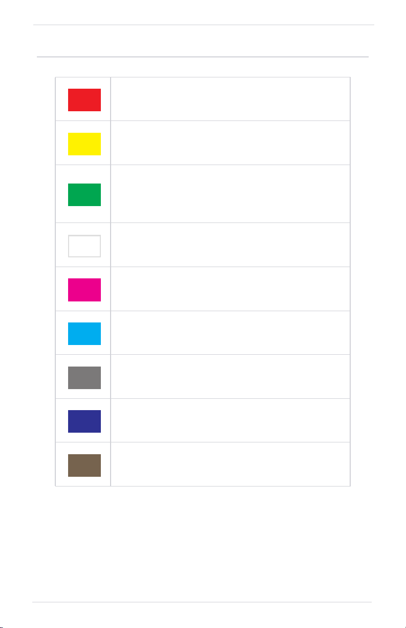
1.7 Color Conventions
Red
• Warning conditions
• Operating limits
Yellow
• Cautionary conditions
• Conditional operating ranges
Green
• Safe operating conditions
• Normal operating ranges
• Engaged modes
White
• Scales and markings
• Current data and values
Magenta
• GPS data
• Active flight plan legs
Cyan
• Pilot-selectable references
System at a Glance
Gray
• Missing or expired data
• Product unavailable
Blue
• Sky
• Water
Brown
• Ground
190-02207-02 Rev. 1 GPS 175/GNX 375 Pilot’s Guide 1-13
Page 30

System at a Glance
Compatible Equipment
1.8 Line Replaceable Units
SYSTEM REQUIRED LRUS
GPS antenna
SYSTEM OPTIONAL LRUS
ADAHRS or ADC with AHRS
GAD 29 adapter
GAE 12 altitude encoder
G3X Touch
G500/G600
G500/G600 TXi
GMX 200
MX 20
OPTIONAL INTERFACES
GDL 88/GTX 345 ADS-B transceiver
(applicable to GPS 175 only)
The system consists of multiple LRUs,
which are installed behind the
instrument panel or in a separate
avionics bay. Their modular design
aids system maintenance and unit
replacement.
Optional LRUs may include
compatible equipment from either
Garmin or a third party manufacturer.
Some LRUs provide features that
require registration and/or
enablement prior to activation.
1-14 GPS 175/GNX 375 Pilot’s Guide 190-02207-02 Rev. 1
Page 31

System at a Glance
1.8.1 ADC & AHRS
The ADC and AHRS sense air data and aircraft attitude for display and use by other
systems. AHRS units have a magnetometer interface for determining magnetic
heading. ADC units have an OAT probe interface for measuring outside air
temperature.
LRU DISPLAY FUNCTION
• Air temperature
GDC 74
ADC
G3X
G500/G600
GSU 25/73
Integrated ADAHRS
GRS 77
AHRS
GNX
GPS
GNX
GNX
GNX
• Airspeed
• Altitude
• Vertical speed
ADC
• Air temperature
• Airspeed
• Altitude
• Vertical speed
AHRS
• Attitude
• Heading
• Rate of turn
• Slip/skid/yaw
• Attitude
• Heading
• Rate of turn
• Slip/skid
1.8.2 Altitude Encoder
LRU DISPLAY FUNCTION
GAE 12
Provides pressure altitude
information to the
transponder.
190-02207-02 Rev. 1 GPS 175/GNX 375 Pilot’s Guide 1-15
GNX Aircraft static pressure
Page 32

System at a Glance
1.8.3 Connext Services
LRU DISPLAY FUNCTION
GDL 88
Provides datalink traffic
and weather.
GTX 345
Overlays Connext
weather products on
moving map and
weather pages.
GPS
Traffic Services
• ADS-B
• TIS-B
Weather Services
• FIS-B
Weather Products
Map & WX page:
• Precip
• METARs
Weather Page:
• Precip
• Winds Aloft
• METARs/TAFs
• AIRMETs
• SIGMETs
• TFRs
• PIREPs
1.8.4 Traffic
LRU DISPLAY FUNCTION
GDL 88
GTX 345
1-16 GPS 175/GNX 375 Pilot’s Guide 190-02207-02 Rev. 1
GPS ADS-B
Page 33

Get Started
2 Get Started
DATABASES
2.1 Database Effective Cycles.......................................................................2-4
2.2 Active and Standby Databases ...............................................................2-5
2.3 Manual Updates ....................................................................................2-6
2.3.1 Database Updates Page ..................................................................2-6
2.4 Automatic Updates................................................................................2-9
2.5 Database Concierge ............................................................................2-10
CONNECTIVITY
2.6 Connext Setup ....................................................................................2-12
2.7 Bluetooth Setup ..................................................................................2-13
2.7.1 Enabling Bluetooth .......................................................................2-13
2.7.2 Managing Paired Devices ..............................................................2-14
2.7.3 Importing a Flight Plan..................................................................2-14
2.8 Wi-Fi Setup..........................................................................................2-15
2.8.1 Connecting to Wi-Fi .....................................................................2-15
XPDR
2.9 XPDR Setup .........................................................................................2-17
2.9.1 Displaying Data ............................................................................2-17
2.9.2 Enabling Extended Squitter Transmissions .....................................2-17
2.9.3 Assigning a Flight ID .....................................................................2-18
2.10 XPDR Modes .......................................................................................2-19
2.11 Squawk Code Keys..............................................................................2-20
2.11.1 VFR ..............................................................................................2-20
2.11.2 IDENT ..........................................................................................2-20
2.12 Remote Control...................................................................................2-22
2.13 XPDR Alert ..........................................................................................2-22
PILOT SETTINGS
2.14 CDI Scale.............................................................................................2-23
2.14.1 Horizontal Alarm Limits ................................................................2-24
2.14.2 CDI On Screen ..............................................................................2-24
2.15 Airport Runway Criteria .......................................................................2-25
2.15.1 Runway Surface............................................................................2-25
2.15.2 Minimum Runway Length.............................................................2-25
2.16 Clocks & Timers...................................................................................2-26
2.16.1 Timers ..........................................................................................2-26
2.16.2 Clock............................................................................................2-26
2.17 Page Shortcuts ....................................................................................2-27
2.18 Alerts Settings .....................................................................................2-28
2.19 Unit Selections.....................................................................................2-29
2.20 Display Brightness Control ...................................................................2-30
2.20.1 Automatic Brightness Control .......................................................2-30
2.20.2 Manual Brightness Control ...........................................................2-30
2.21 Scheduled Messages ...........................................................................2-31
2.21.1 Message Types .............................................................................2-31
2.21.2 Modifying Scheduled Messages ....................................................2-31
190-02207-02 Rev. 1 GPS 175/GNX 375 Pilot’s Guide 2-1
Page 34

Get Started
STATUS INDICATIONS
2.22 Alert Types ..........................................................................................2-32
2.22.1 Alert Annunciations ......................................................................2-33
2.22.2 Pop-up Alerts ...............................................................................2-34
2.22.3 Aural Alerts ..................................................................................2-34
2.23 System Status Page..............................................................................2-35
2.24 GPS Status Page ..................................................................................2-35
2.24.1 Circle of Uncertainty .....................................................................2-37
2.24.2 SBAS Providers .............................................................................2-38
2.24.3 GPS Status Annunciations.............................................................2-38
2.24.4 GPS Alerts ....................................................................................2-39
2.25 ADS-B Status Page...............................................................................2-40
LOGS
2.26 Exporting to SD Card ..........................................................................2-41
2-2 GPS 175/GNX 375 Pilot’s Guide 190-02207-02 Rev. 1
Page 35

Get Started
Databases
NOTE
The navigator supports SD cards in the FAT32 format only, with capacities
ranging between 8 GB and 32 GB.
Databases are stored in the unit’s internal memory. To view update cycles, or to
purchase individual databases or database packages, go to
There are two methods for loading and updating databases:
1. Load databases via SD card. The card may be removed after loading.
2. Transfer databases from a Flight Stream 510 wireless datacard. Requires Garmin
Pilot application on a portable electronic device.
SUPPORTED DATABASES
Basemap
Navigation
Obstacles Obstacle and wire data
SafeTaxi Airport surface diagrams
Terrain Terrain elevation data
Bodies of water, geopolitical boundary, and road
information
Airport, NAVAID, waypoint, and airspace information
(Garmin or Jeppesen)
flyGarmin.com.
For information regarding third party navigation databases, go to jeppesen.com.
190-02207-02 Rev. 1 GPS 175/GNX 375 Pilot’s Guide 2-3
Page 36

Get Started
2.1 Database Effective Cycles
Most databases expire at regular intervals. Exceptions include Basemap and Terrain,
which neither expire nor update on a regular schedule.
The start-up page lists all currently
installed databases. Review this list for
current database types, cycle numbers,
and expiration dates.
Yellow text denotes when a database is:
• Not available
• Installed before its effective date
• Missing date information
• Past its expiration date
DATABASE EFFECTIVE STATUS
• Effective upon release
Databases with
no effective
date
Databases with
specified
effective dates
• Transfer occurs prior to database verification at system
start-up
• No automatic transfer if Flight Stream 510 is present
• Includes Basemap and Terrain
• No pilot confirmation or restart required
• Effective during a specific period
• Unit determines database status using the current date
and time from GPS
• Automatic activation occurs on the effective date
DATABASE NOT FOUND
Notifications for databases not present or available also display in the form of system
messages.
Tapping Database Info
opens the Active Database
Information page.
Review this list to determine
the status of the indicated
database.
2-4 GPS 175/GNX 375 Pilot’s Guide 190-02207-02 Rev. 1
Page 37

Get Started
2.2 Active and Standby Databases
The navigator uses two types of databases: active and standby. Active databases are
in use by the system. Standby databases have not reached the effective date. During
normal operation, information about all active and standby databases are viewable
on the associated info page.
From the Home page, tap System > System Status > Select Active or Standby.
DB INFO PAGE DISPLAYS
Active
Standby • Information about databases that are not yet effective
• Information about databases currently in use
• View Copyrights key
The Standby DB Info page notifies when
no standby databases are available.
VIEW COPYRIGHTS
Tapping this key displays copyright information for all
installed databases.
190-02207-02 Rev. 1 GPS 175/GNX 375 Pilot’s Guide 2-5
Page 38

Get Started
2.3 Manual Updates
FUNCTIONAL LIMITATIONS
The Database Updates page is available only when:
• The aircraft is on ground
• The start-up page is active (i.e., during power up)
2.3.1 Database Updates Page
This page presents a list of all available databases.
To open, tap the Databases key on the start-up page.
2
1
3
DATABASE SOURCE INDICATION
Connext Icon
A Connext icon indicates when a
database is from Garmin Pilot via
wireless transfer.
No indication means the database is either from an SD card or the unit’s internal
standby queue.
2-6 GPS 175/GNX 375 Pilot’s Guide 190-02207-02 Rev. 1
Page 39

SELECT ALL DATABASES
Select individual databases for transfer, or choose Select All if all
listed databases require updating.
Basemap and Terrain update automatically and
require no action.
Get Started
After all selections are made,
initiate the update process by
tapping Start.
By default, this page displays only
the databases recommended for
update.
A message notifies when no such
databases are available.
The unit automatically restarts
once all updates are complete.
SHOW ALL DATABASES
Tapping Show All displays a complete list of all databases.
This list may include databases
that are:
• Not yet effective
• Older than the currently
Error
Icon
190-02207-02 Rev. 1 GPS 175/GNX 375 Pilot’s Guide 2-7
Older
Timestamp
active database(s)
• Unable to update due to
an error
Page 40

Get Started
ERROR INFORMATION
To determine the cause of a database error, tap Error Info.
SELECT REGION
An information window provides
details regarding the state of the
database.
This key appears when two
databases are of the same type
and cycle, but pertain to different
regions.
To specify a database region, tap
Select Region, then select the
appropriate menu option.
2-8 GPS 175/GNX 375 Pilot’s Guide 190-02207-02 Rev. 1
Page 41

Get Started
2.4 Automatic Updates
AUTOMATIC UPDATES OCCUR WHEN...
• A newer database is detected on the SD card or in the
internal standby queue
• A newer database is within its effective dates
• The aircraft is on ground
When a newer database is available, follow the on-screen prompts to complete the
update process.
A status page displays a progress bar and the name of each database as it uploads to
the unit. Terrain databases may require up to 5 minutes for transfer. Total transfer
time depends on the SD card type.
The unit automatically restarts once the update is complete. The update is indicated
in the list of currently installed databases.
INSTALL OR UPDATE A DATABASE USING AN SD CARD
1. Download a database onto an SD card.
2. Insert the SD card with the most recent database(s) into the card slot.
3. Power on the unit.
Selecting Update opens the DB Updates page.
A list displays the newest databases.
All newer databases (effective and expired)
transfer from the SD card to the internal
standby queue.
BASEMAP AND TERRAIN UPDATES
These databases automatically transfer from an SD card without any prompting or
progress indications. They do not require pilot confirmation or a unit restart.
190-02207-02 Rev. 1 GPS 175/GNX 375 Pilot’s Guide 2-9
Page 42

Get Started
2.5 Database Concierge
FEATURE REQUIREMENTS
• Flight Stream 510 wireless datacard
• Garmin Pilot app on a mobile device
Database Concierge allows wireless transfer of databases
from a mobile device.
A pilot selects and downloads databases inside the Garmin
Pilot app. Transfers occur once Flight Stream 510 establishes a
wireless connection inside the aircraft.
DATABASE CONCIERGE TRANSFER FUNCTIONS
• Automatic updates for databases with effective dates
• Preloads databases that are not yet effective by placing them in the internal
standby queue
• Displays database type, cycle, effective date, and transfer progress
• Start key for manual operation
• Pilot confirmation required
TRANSFER A DATABASE USING DATABASE CONCIERGE
1. Purchase database(s) from flyGarmin.com.
2. Open Garmin Pilot and follow the download instructions.
3. Install Flight Stream 510 and then power on unit.
4. Connect to Wi-Fi.
5. Follow the on screen prompts.
2-10 GPS 175/GNX 375 Pilot’s Guide 190-02207-02 Rev. 1
Page 43

Get Started
Database Concierge transfers
databases from the app to
Flight Stream 510.
A progress bar shows when this
process is complete.
Database Transfer Status
The unit either updates or
preloads databases based on
their effective date. A second
progress bar indicates upload
Database Update Status
Tapping Skip cancels any unfinished wireless transfers and
initiates the update process.
The unit activates any databases that completed transfer before the interruption.
Previously selected databases on an SD card or in the internal standby update as well.
The message “Transfers interrupted” displays if no databases are available.
status. The unit automatically
restarts upon database activation.
190-02207-02 Rev. 1 GPS 175/GNX 375 Pilot’s Guide 2-11
Page 44

Get Started
Connectivity
Data logs transfer over Bluetooth.
FEATURE LIMITATIONS
• Unit allows pairing of up to 13 Bluetooth devices, with two simultaneous
device connections
• Auto reconnect function is not available for Android devices
2.6 Connext Setup
Connext works via the Bluetooth data link to
provide up-to-date, wireless information
throughout the cockpit.
The Connext interface allows communication with applications (i.e., Garmin Pilot
and ForeFlight Mobile) while running on a portable electronic device.
Connext Features
The following features are available on your portable electronic device.
• GPS position and velocity information [1] [2]
• ADS-B In traffic data [1]
• FIS-B weather and flight information [2]
• Uncorrected barometric pressure altitude used by transponder and ADS-B [1]
• AHRS data via Connext and a built-in sensor [2] [3]
[1] GNX 375 only.
[2] External ADS-B In device required for GPS 175.
[3] Occurs when GNX 375 is installed as a standalone device. Attitude data does not output to
other installed avionics.
[4] The internal AHRS sensor is only for use with a portable electronic device. All internal AHRS
functions are automatic and do not require pilot action.
2-12 GPS 175/GNX 375 Pilot’s Guide 190-02207-02 Rev. 1
Page 45

2.7 Bluetooth Setup
Get Started
BLUETOOTH FEATURES
• FIS-B weather [1]
• ADS-B traffic [1]
• GPS/WAAS position, velocity,
and time
• Pressure altitude
• AHRS
• Magnetic heading
• Flight plan transfer
[1] GNX 375, or GPS 175 with external ADS-B In source.
The unit supports Bluetooth pairing
with up to 13 portable electronic
devices via the Garmin Pilot app.
Bluetooth management options reside
on the Devices page. Opening this page
automatically initiates device pairing.
Device information and pairing mode
status display on the Connext page.
2.7.1 Enabling Bluetooth
Tapping Bluetooth Enabled
toggles Bluetooth functionality
on or off.
All associated setting controls and
features are unavailable when this
function is inactive.
DEVICE NAME
Allows entry of the Bluetooth device name. Use the
keypad or control knobs to enter the Bluetooth name.
190-02207-02 Rev. 1 GPS 175/GNX 375 Pilot’s Guide 2-13
Page 46

Get Started
2.7.2 Managing Paired Devices
To view a list of all paired devices
and their connection status, tap
Paired Devices.
AUTO RECONNECT
Enables automatic connection between the unit and the paired device when the two
are within range.
REMOVE
Removing a device from the list means it is no longer paired with the unit. This action
requires pilot confirmation.
Be sure to remove pairing on both devices before attempting to pair them again.
PAIRING STATUS
The device is configured and communicating properly.
The device is not available and is not configured or it is not
communicating properly.
2.7.3 Importing a Flight Plan
This feature allows automatic import of flight plans via
Bluetooth.
It may be necessary to turn this function off if a portable
device application makes repeated erroneous attempts to
send flight plans to the unit.
2-14 GPS 175/GNX 375 Pilot’s Guide 190-02207-02 Rev. 1
Page 47

Get Started
2.8 Wi-Fi Setup
Tapping WiFi Info opens an information page. This page is
accessible from the Database Update and start-up pages.
Information includes:
• Database Concierge
connection status
• Connected device name
• Database update availability
and instructions
• Wi-Fi SSID and password
WI-FI INFO STATUS
Wi-Fi connection status annunciates on the key label when the information page is
not active.
Flight Stream 510 requires power up.
Wi-Fi is active, but the unit is waiting to connect with a
connected device.
Connection complete. Flight Stream 510 requires Garmin
Pilot to be opened in order for database transfer to
commence.
Garmin Pilot opened and streaming to unit.
2.8.1 Connecting to Wi-Fi
Follow the onscreen prompts when connecting to the Wi-Fi network.
1. Install Flight Stream 510 and then power on unit. Observe Wi-Fi status changes
from “Offline” to “Ready.”
2. Tap Wi-Fi Info.
3. Enter the required SSID and password using the provided keypads.
4. Enable Wi-Fi setting on the portable device. Wi-Fi status changes to
“Open App” once pairing is complete.
190-02207-02 Rev. 1 GPS 175/GNX 375 Pilot’s Guide 2-15
Page 48

Get Started
XPDR
FEATURE LIMITATIONS
• GNX 375 only.
Transponder controls are accessible via the IDENT key.
1
2
3
XPDR Control Panel
1 Squawk Code Entry Field 4 Squawk Code Entry Keys
2 VFR Key 5 Data Field
3 XPDR Mode Key
5
4
2-16 GPS 175/GNX 375 Pilot’s Guide 190-02207-02 Rev. 1
Page 49
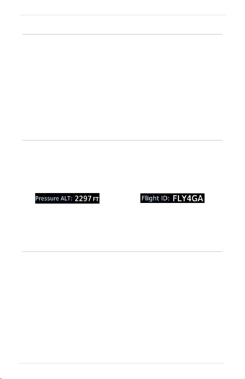
2.9 XPDR Setup
2.9.1 Displaying Data
Toggles the data field between pressure altitude and
flight ID.
Pressure Altitude Flight ID
Get Started
Tap Menu to access the transponder setup
options. From here you can:
• Change the display of data
• Enable 1090 ES ADS-B Out
functionality
• Assign a unique flight ID
Displays the current pressure
altitude.
Displays the active Flight ID.
Unless configured, the
Flight ID is not editable.
2.9.2 Enabling Extended Squitter Transmissions
Tapping ADS-B Out allows the transmission of ADS-B Out
messages and position information.
190-02207-02 Rev. 1 GPS 175/GNX 375 Pilot’s Guide 2-17
Page 50

Get Started
2.9.3 Assigning a Flight ID
FEATURE LIMITATIONS
• Availability dependent on configuration
If the flight ID is editable, tap Flight ID
and assign a unique identifier.
Flight IDs are alphanumeric (upper-case
only) and have an eight character limit.
The active flight ID displays by default.
2-18 GPS 175/GNX 375 Pilot’s Guide 190-02207-02 Rev. 1
Page 51

2.10 XPDR Modes
Tapping Mode opens a menu of the available transponder
modes. Options include Standby, On, and Altitude Reporting.
MODE FUNCTION
• Transponder does not reply to interrogations or
transmit ADS-B Out
Standby
On
Altitude
Reporting
• Bluetooth functions remain operational
• Unit continues to receive ADS-B In information, but is
not a TIS-B participant
• Transponder replies to interrogations. Replies do not
include pressure altitude
• Reply (R) symbol on the display indicates the
transponder is responding
• Transponder replies to identification and altitude
interrogations
• Reply (R) symbol indicates the transponder is
responding
• GNX 375 transmissions include pressure altitude
Get Started
During Altitude Reporting mode, all aircraft air/ground state transmissions are
handled via the transponder and require no pilot action. Always use this mode
while in the air and on the ground, unless otherwise requested by ATC.
190-02207-02 Rev. 1 GPS 175/GNX 375 Pilot’s Guide 2-19
Page 52

Get Started
2.11 Squawk Code Keys
SPECIAL SQUAWK CODES
1200 Default VFR code (USA)
7500 Hijacking
7600 Loss of communications
7700 Emergency
Digits that are not yet entered appear as underscores.
2.11.1 VFR
Eight squawk code entry keys (0 – 7)
provide access to all ATCRBS codes.
Pressing one of these keys begins the
code selection sequence.
Use the Backspace key or outer
control knob to move the cursor.
Entering the fourth digit activates
the new code.
To cancel the code entry and exit
the page, tap Cancel.
Active squawk codes remain in use until
a new code is entered.
Tapping this key once sets the squawk code to the
preprogrammed VFR code.
This code is factory set to 1200, but may be changed during
configuration.
2.11.2 IDENT
Active
Transponder
Active Squawk
Code
2-20 GPS 175/GNX 375 Pilot’s Guide 190-02207-02 Rev. 1
Transponder
Mode (On)
Tapping this key activates the
IDENT function for 18 seconds.
This signal distinguishes the
transponder from others on
the air traffic controller’s
screen.
Page 53

TRANSPONDER STATUS INDICATIONS
IDENT Standby Mode
Get Started
• Reply active
• Identify function active
• No change to
transponder code
IDENT with New Squawk Code Altitude Reporting Mode
• Reply active
• Transponder code
modified
• Standby mode
• Current squawk code
(inactive)
• Altitude reporting mode
• Reply active
• Identify function active
• VFR squawk code
(active)
SYMBOL MEANING
Reply active
Identify function active
Transponder in operation
Altitude Reporting
Standby
Press to initiate the IDENT function (code unmodified)
Press to accept modified code and initiate IDENT function
190-02207-02 Rev. 1 GPS 175/GNX 375 Pilot’s Guide 2-21
Page 54

Get Started
2.12 Remote Control
Transponder functions are controllable from a connected G3X Touch display.
Control features include:
• Squawk code • Transponder mode
• IDENT • ADS-B transmission
• Flight ID
For transponder control operation, consult the G3X Touch Pilot’s Guide.
2.13 XPDR Alert
If the transponder fails:
• Red “X” displays over the IDENT key
• Advisory message alerts
• XPDR control page is not available
Transponder fail annunciations are designed to be immediately recognizable.
If a failure occurs while the control page is active, the display automatically returns
to the previous page.
UNIT CONDITION
GPS 175 GDL 88 failure.
GNX 375 ADS-B interboard communication failure.
For information regarding pilot response to a transponder failure, consult the
AFMS.
2-22 GPS 175/GNX 375 Pilot’s Guide 190-02207-02 Rev. 1
Page 55

Pilot Settings
2.14 CDI Scale
Get Started
System customization
options allow you to:
• Set and display the CDI
• Specify runway criteria
• Set the date and time
• Create shortcuts
• Set the display units
• Adjust display
brightness
Other setup options allow
you to monitor time in flight
and create custom reminder
messages. These reside in the
system Utilities.
Set the scale for the course deviation indicator.
Scale values represent full scale deflection for the
CDI to either side.
Options: • 0.30 nm • 1.00 nm • 2.00 nm • Auto
By default, the scale is set to “Auto.” At this setting, the CDI scale is set to 2.0 nm
during the en route phase of flight.
Within 31 NM (terminal area) of your destination airport, the CDI scale linearly ramps
down to 1.0 NM over a distance of 1 NM.
Likewise, when leaving your departure airport the CDI scale is set to 1.0 NM and
gradually ramps up to 2 NM beyond 30 NM (from the departure airport). During GPS
approach operations the CDI scale gradually transitions down to an angular CDI
scale.
At 2.0 NM before the final approach fix (FAF), CDI scaling is tightened from 1.0 NM
to the angular full scale deflection (typically the angular full-scale deflection is 2.0°,
but will be as defined for the approach)
If a lower CDI scale setting is selected (i.e., 1.0 or 0.3 NM), the higher scale settings
are not selected during ANY phase of flight. For example, if 1.0 NM is selected, the
unit uses this for en route and terminal phases and ramps down further during an
approach.
190-02207-02 Rev. 1 GPS 175/GNX 375 Pilot’s Guide 2-23
Page 56

Get Started
2.14.1 Horizontal Alarm Limits
Horizontal alarm limits (HAL) follow the selected CDI scale, unless the corresponding
flight phase requires a lower alarm limit. For example, the selected scale setting is
1.0 nm, but full-scale deflection during approach still follows the approach scale
setting (0.30 nm).
FLIGHT
PHASE
Approach 0.30 nm or Auto 0.30 nm
Terminal 1.00 nm or Auto
En Route 2.00 nm or Auto
Oceanic Auto
CDI SCALE
HORIZONTAL
ALARM LIMIT
1.00 nm
2.00 nm
2.00 nm
2.14.2 CDI On Screen
Toggling this setting displays the CDI scale on screen. When active, a CDI with lateral
deviation indicator displays below the GPS NAV Status Indicator key.
CDI OFF CDI ON
Only the Flight Plan page
access key is available.
The CDI provides no indications
without an active flight plan.
Lateral Deviation Indicator Visual Approach Guidance
Lateral deviation indications
display when there is an active
flight plan.
2-24 GPS 175/GNX 375 Pilot’s Guide 190-02207-02 Rev. 1
Advisory horizontal and vertical
guidance annunciations appear
when a visual approach
procedure is active.
Page 57

2.15 Airport Runway Criteria
Specify runway criteria from the System Setup page.
Selections determine which airports are suitable when
using the nearest airport search feature.
During an approach, the terrain alerting algorithm
uses airport runway settings to avoid nuisance alerts.
2.15.1 Runway Surface
Get Started
RUNWAY SURFACE OPTIONS
• Any
• Hard Only
• Hard/Soft
• Water
Tap Runway Surface and then select
the runway surface type.
Selecting “Any” allows all surface types
to display on the map.
2.15.2 Minimum Runway Length
Specify a minimum runway length to prevent the display of airports with shorter
runways. Typing “0” allows runways of any length to display.
190-02207-02 Rev. 1 GPS 175/GNX 375 Pilot’s Guide 2-25
Page 58

Get Started
2.16 Clocks & Timers
2.16.1 Timers
Monitor time in flight using three available timer types.
Timer settings are accessible via the Utilities
menu page. Toggle between timer types
using the provided display key.
Clock/Generic Timer Trip/Departure Timers
Stopwatch style counter.
Count up or count down.
Specify countdown time
using the preset function.
Controls:
• Direction (Up, Down)
• Start • Stop • Timer Preset
Measure elapsed airborne time
since the last ground-to-air
transition. Set timer to start at
unit power up or once the
aircraft is in air.
Controls:
• Criteria (Power On, In Air)
• Reset Timer
2.16.2 Clock
Specify the time format and local offset. Settings
reside in the System Setup page.
Format options include 12 hour, 24 hour, and UTC.
If a 12 hour or 24 hour clock is selected:
Tap Local Offset > Specify the appropriate offset value from UTC.
2-26 GPS 175/GNX 375 Pilot’s Guide 190-02207-02 Rev. 1
Page 59

2.17 Page Shortcuts
A knob shortcut option allows you to customize slots 2 and 3 of
the locator bar. Slot one is reserved for the Map page.
Tap a slot key and assign a page to that slot.
Get Started
PAGE SHORTCUT OPTIONS
• Traffic
• Terrain
• Weather
• Nearest
Airport
• Flight Plan
Tapping Restore Defaults returns both slots to their default
settings (Terrain for Slot 2, Nearest Airport for Slot 3).
Depending on configuration, Traffic
and Weather shortcuts may not be
available.
Verify shortcut operation once
complete.
190-02207-02 Rev. 1 GPS 175/GNX 375 Pilot’s Guide 2-27
Page 60

Get Started
2.18 Alerts Settings
Airspace alerts generate a message and filtering of the Nearest
Airspace list. They rely on three-dimensional data (altitude,
latitude, and longitude) to avoid nuisance alerts.
FEATURE LIMITATIONS
• Alert altitudes are dependent on aircraft and airspace altitudes and the
pilot-specified altitude buffer value
Control keys allow you to select which airspace boundaries
generate an alert annunciation upon entry.
Alert boundaries for controlled airspace are
sectorized to provide complete information
on any nearby airspace.
Alert settings do not alter the depiction of
airspace, nor do they change Smart Airspace
settings on the Map page.
With the exception of Altitude Buffer,
airspace alert options are on/off only.
Airspace alerts for Prohibited airspace
cannot be disabled.
2-28 GPS 175/GNX 375 Pilot’s Guide 190-02207-02 Rev. 1
Page 61

2.19 Unit Selections
Customize the display unit settings. Tapping a parameter key
opens a menu of the available unit types.
PARAMETER SETTINGS
Distance/Speed
Temperature
NAV Angle
Magnetic
Variation
SPECIFY UNIT TYPE
1. Review the current unit selections.
2. Tap the applicable parameter key.
3. Select a unit type.
• Nautical Miles (nm/kt)
• Statute Miles (sm/mph)
• Celsius (ºC)
• Fahrenheit (ºF)
• Magnetic (º)
• True (ºT)
• User (ºU)
• Specify number of degrees for east or west (ºE, ºW)
• Available only when “User (ºU)” is the active
NAV angle
Get Started
190-02207-02 Rev. 1 GPS 175/GNX 375 Pilot’s Guide 2-29
Page 62

Get Started
2.20 Display Brightness Control
Depending on configuration, display brightness is controlled using
inputs from the built in photocell, aircraft dimmer bus, or both.
2.20.1 Automatic Brightness Control
Dimming is limited to prevent on screen indications from becoming unreadable. The
built in photocell automatically controls display brightness based on ambient light
levels.
Backlight
Intensity Level
Manual Offset
Indicator
During automatic control, the pilot
may still adjust brightness using
the manual offset controls in the
Backlight page.
The unit retains manual offset
settings over power cycles.
Decrease
Backlight
Increase
Backlight
2.20.2 Manual Brightness Control
Optionally, the unit is configurable to use an aircraft dimming bus for display
brightness control. Upon reaching minimum input level, display brightness reverts to
the photocell. This prevents the display from going black in the event of a dimmer
input failure.
Installer configured curves determine the amount of change in brightness that
occurs in response to a control adjustment.
If brightness control is not satisfactory, contact a Garmin dealer to adjust the
lighting curves.
2-30 GPS 175/GNX 375 Pilot’s Guide 190-02207-02 Rev. 1
Page 63

2.21 Scheduled Messages
Create custom reminder messages and set when they will display.
Allows one time, periodic, and event-based message types.
Active reminders appear at the top of
the scheduled message list. This list is
accessible via the Utilities menu page.
Examples: • “Call FBO” • “Close flight
plan” • “Switch fuel tanks”
CREATE A REMINDER MESSAGE
1. Tap Create Scheduled Message.
2. Specify the message type, content, and countdown timer value.
2.21.1 Message Types
TYPE DISPLAY
One time
Periodic
Event
Displays when the timer expires, or following each power
cycle until message deletion.
Displays after a specified duration of time. Countdown
repeats once the message displays.
Based a specified date and time. Message timer not
applicable.
Get Started
2.21.2 Modifying Scheduled Messages
Once created, these messages may be modified at any time. Selecting a scheduled
message opens an options menu.
EDIT MESSAGE
This function is accessible from either the Scheduled Messages page or the system
message list.
RESET TIMER
Restarts the countdown timer.
DELETE MESSAGE
Confirming this request removes the selected message from the list.
190-02207-02 Rev. 1 GPS 175/GNX 375 Pilot’s Guide 2-31
Page 64

Get Started
Status Indications
2.22 Alert Types
The unit generates annunciations in response to various conditions that may occur.
These abbreviated messages are grouped according to the level of urgency and
required response. They display in order of priority, from highest to lowest.
1. Warnings
2. Cautions
3. Mode & function advisories
WARNINGS & CAUTIONS
Warnings require immediate attention. Cautions indicate the presence of an
abnormal condition that may require pilot action. A warning may follow a caution if
no attempt is made to correct the condition (e.g., altering the aircraft’s path toward
the alerted terrain or obstacle).
MODE & FUNCTION ADVISORIES
Advisories provide status and operating information.
System advisories display on a dedicated page or slide over window. Depending on
the number of advisories, this list may be scrollable.
Function or mode specific advisories appear as unobstructed annunciations on the
associated display.
System
Messages
Page
Mode Advisory Annunciation
2-32 GPS 175/GNX 375 Pilot’s Guide 190-02207-02 Rev. 1
Page 65

Get Started
2.22.1 Alert Annunciations
Alert annunciations are abbreviated messages that indicate an alerted function or
mode. The color of the annunciation depends on the alert type.
ALERT COLORS
WARNING
CAUTION
ADVISORY
When an alert is triggered, the annunciation flashes by alternating text and
background colors. It turns solid after five seconds. All annunciations remain active
(solid) until the condition is resolved or no longer a threat.
ANNUNCIATION LOCATION
Alerts and informational advisories annunciate in the annunciator bar along the
bottom of the screen.
• Warnings display in white text on red
background
• Cautions display in black text on amber
background
• Function or mode specific advisories display in
black text on white background
and Test Mode
Advisories
ProcedureFlight PhaseAlerts, Inhibits
Waypoint and
Power Off
Advisories
190-02207-02 Rev. 1 GPS 175/GNX 375 Pilot’s Guide 2-33
Page 66

Get Started
2.22.2 Pop-up Alerts
If a warning or caution relating to terrain or traffic occurs, a pop-up window may
display. These pop-ups only appear if the alerted function’s associated page is not
active.
POP-UP ALERT PRIORITY
In the event of simultaneous
alerts, pop-up windows display in
the following order:
1. Terrain alerts
2. Traffic alerts
1 Threat Indication 4 Alert Inhibit Key
2 Alert Annunciation 5 Go to <Page> Key
Each pop-up alert provides:
• Threat indication
• Alert annunciation
• Option to inhibit or mute the alert
• Control for closing the pop-up window
• Direct access to the associated page
Pop-up Alert Layout
3 Close Pop-up Window Key
To open the indicated page, tap Go to <Page>.
To acknowledge the alert and return to previous page view, tap Close.
2.22.3 Aural Alerts
FEATURE LIMITATIONS
• GNX 375 only (traffic alerts)
Traffic alerts are accompanied by an aural voice message. Voice gender is configured
during installation.
2-34 GPS 175/GNX 375 Pilot’s Guide 190-02207-02 Rev. 1
Page 67

2.23 System Status Page
View information specific to the unit and its software. Refer here
when contacting customer service.
DATA FIELDS CONTROLS
• Serial number
• System ID
• Main software version
• GPS/WAAS software version
• Transponder software version
(GNX 375 only)
Database Info access keys:
• Active
• Standby
2.24 GPS Status Page
Monitor GPS receiver performance, establish a baseline for normal
system operation, and troubleshoot weak or missing signal issues.
Get Started
This page provides a visual reference of GPS receiver functions, including:
• Current satellite coverage • GPS solution and receiver status
• Phase of flight • Position accuracy
• Present position
(latitude and longitude)
SKY VIEW DISPLAY
• Depicts satellites currently in view as well as their
respective positions.
• Outer circle represents the horizon
(with north at the top of the circle)
• Inner circle represents 45° above the horizon
• Center point shows the position directly overhead
190-02207-02 Rev. 1 GPS 175/GNX 375 Pilot’s Guide 2-35
Page 68

Get Started
SIGNAL STRENGTH INDICATIONS
SATELLITE SVIDS
Each bar is labeled with the SVID
of the corresponding satellite.
Numbers vary according to
satellite type.
• GPS:1to31
• SBAS: 120 to 138
A graph shows GPS signal strength for up
to 15 satellites. As the GPS receiver locks
onto satellites, a signal strength bar appears
for each satellite in view.
Graph symbols depict the progress of
satellite acquisition. Some data may not
display until the unit has acquired enough
satellites for a fix.
SYMBOL CONDITION
Not present Receiver is searching for the indicated satellites.
Gray bar, empty
Gray bar, solid
Yellow bar, solid
Cyan bar,
cross-hatch
Cyan bar, solid
Green bar, solid
D (inside bar)
Satellite located.
Satellite located, receiver is collecting data.
Data collected, but satellite is excluded from position
solution (i.e., it is not in use).
Satellite located, but FDE excludes it for being a faulty
satellite.
Data collected, but receiver is not using satellite in the
position solution.
Data collected, satellite in use in the current position
solution.
Differential corrections are in use (e.g., WAAS).
2-36 GPS 175/GNX 375 Pilot’s Guide 190-02207-02 Rev. 1
Page 69

Get Started
POSITION ACCURACY FIELDS
LABEL POSITION DATA
EPU Estimated Position Uncertainty
HDOP Horizontal Dilution of Precision
HFOM Horizontal Figure of Merit
VFOM Vertical Figure of Merit
EPU is the horizontal position error estimated by the
fault detection and exclusion algorithm, in feet or
meters.
Information fields indicate the
accuracy of the position fix.
HFOM and VFOM values
represent 95% confidence levels
in horizontal and vertical
accuracy.
Lower values mean higher
accuracy. Higher values are the
least accurate.
FDE PREDICTION
NOTE
Under FAR parts 91, 121, 125, and 135, FDE must be used prior to all
oceanic or remote area flights using the GPS 175/GNX 375 as a primary
means of navigation.
This program uses an algorithm to predict FDE availability. If the unit has not been in
operation for more than six months, acquiring satellite data to establish almanac and
satellite orbit information may take 5 to 10 minutes.
2.24.1 Circle of Uncertainty
FEATURE LIMITATIONS
• Available only when the aircraft is on ground
• Displays only on the Map page
• Depicts area surrounding the ownship when GPS
cannot accurately determine aircraft location
• Expands as GPS horizontal accuracy degrades
• Shrinks as accuracy improves
• Transparent so as not to obstruct other features
190-02207-02 Rev. 1 GPS 175/GNX 375 Pilot’s Guide 2-37
Page 70

Get Started
2.24.2 SBAS Providers
NOTE
Operating with SBAS active outside of the service area may cause elevated
EPU values to display on the status page. Regardless of the EPU value
displayed, the LOI annunciation is the controlling indication for
determining the integrity of the GPS navigation solution.
SBAS supports wide area or regional augmentation through the
use of additional satellite broadcast messages.
Tap this key and select from the list of providers.
PROVIDER SERVICE AREAS
EGNOS Most of Europe and parts of North Africa.
GAGAN
MSAS
WAAS
India
Japan only.
Alaska, Canada, the 48 contiguous states,
and most of Central America.
2.24.3 GPS Status Annunciations
Once the GPS receiver determines the aircraft’s position, the unit displays position,
altitude, track, and ground speed data. GPS status annunciates under the following
conditions.
ANNUNCIATION CONDITION
GPS receiver uses last known position and satellite orbital
Acquiring
3D Nav
3D Diff Nav
LOI
2-38 GPS 175/GNX 375 Pilot’s Guide 190-02207-02 Rev. 1
data (collected continuously from satellites) to determine
which satellites should be in view.
3-D navigation mode. GPS receiver computes altitude
using satellite data.
3-D navigation mode. Differential corrections from SBAS
provider are in use.
Satellite coverage is insufficient to pass built-in integrity
monitoring tests.
Page 71

2.24.4 GPS Alerts
The following alert conditions can affect GPS accuracy.
INDICATIONS FAULT TYPE CONDITION
Integrity of the GPS position does
Yellow “LOI”
annunciation.
Unit invalidates
active course
guidance.
Annunciation is
specific to cause.
Yellow “No GPS
Position”
annunciation.
Ownship icon not
present
Loss of Integrity
Loss of Navigation
Loss of Position
not meet the requirements for the
current phase of flight. Occurs
before the final approach fix
(if an approach is active).
Aircraft is after the final approach
fix and GPS integrity does not meet
the active approach requirements.
Insufficient number of satellites
supporting aircraft position (i.e.,
more than 5 seconds pass without
adequate satellites to compute a
position).
GPS sensor detects an excessive
position error or failure that cannot
be excluded within the time to
alert.
On-board hardware failure.
Unit cannot determine a GPS
position solution.
Get Started
190-02207-02 Rev. 1 GPS 175/GNX 375 Pilot’s Guide 2-39
Page 72

Get Started
2.25 ADS-B Status Page
View last uplink time and GPS source information.
FEATURE REQUIREMENTS
• GDL 88 or GTX 345 ADS-B transceiver (GPS 175 only)
UPLINK TIME
TEXT
MINUTES SINCE
COLOR
Green < 5
Yellow
5to15
>15
LAST UPLINK
Dashes indicate when valid uplink data is
unavailable (e.g., the device is offline).
FIS-B WX STATUS
Tapping this key opens the FIS-B Weather Status page.
This page is also accessible from the FIS-B Weather setup
menu.
TRAFFIC APPLICATION STATUS
Tap this key to view the status of the three traffic
applications: • AIRB • SURF • TSAA (airborne alerts)
ANNUNCIATION DESCRIPTION
On
Available to Run
Unavailable to Run
Unavailable - Fault
Application is running. Required ownship data is
available and meets the performance criteria.
Application is configured. Required input data is
available and meets the performance criteria.
ASA application is off.
Required input data is not available due to a failure
(e.g., ASA application process failed).
Required input data is available, but does not meet
the performance criteria or is not available due to
non-computed data conditions.
2-40 GPS 175/GNX 375 Pilot’s Guide 190-02207-02 Rev. 1
Page 73

Logs
2.26 Exporting to SD Card
A logging function stores WAAS diagnostic data in the unit’s
internal memory. This information is available for export to an
SD card for later analysis.
FEATURE REQUIREMENTS
• SD card
The export function resides in the Logs page.
This function is not available if no log files are present.
WAAS Diagnostic Log Functions
• Generates log files automatically upon unit power-up
• Provides WAAS engine data in the form of serial text messages
• Overwrites oldest file when the internal log reaches capacity
• Exports to the “log_files” folder on the SD card
Get Started
190-02207-02 Rev. 1 GPS 175/GNX 375 Pilot’s Guide 2-41
Page 74

INTENTIONALLY LEFT BLANK
2-42 GPS 175/GNX 375 Pilot’s Guide 190-02207-02 Rev. 1
Page 75

Navigation
3 Navigation
MAP
3.1 Map Interactions ...................................................................................3-6
3.1.1 Basic Interactions ............................................................................3-6
3.1.2 Graphical Flight Plan Editing ...........................................................3-8
3.2 Map Setup ..........................................................................................3-12
3.2.1 Configure User Fields....................................................................3-13
3.2.2 Map Orientation ...........................................................................3-14
3.2.3 North Up Above ...........................................................................3-15
3.2.4 Visual Approach ...........................................................................3-15
3.2.5 TOPO Scale...................................................................................3-15
3.2.6 Range Ring ...................................................................................3-16
3.2.7 Track Vector .................................................................................3-16
3.2.8 Ahead View..................................................................................3-16
3.2.9 Map Detail ...................................................................................3-17
3.3 Map Overlays ......................................................................................3-19
3.3.1 Overlay Controls ...........................................................................3-19
3.3.2 Overlay Status Icons ......................................................................3-22
3.3.3 Smart Airspace .............................................................................3-23
3.3.4 SafeTaxi........................................................................................3-24
ACTIVE FLIGHT PLAN
3.4 Edit Data Fields ....................................................................................3-28
3.5 Collapse All Airways ............................................................................3-28
3.6 Parallel Track ....................................................................................... 3-29
3.7 Flight Plan Catalog ..............................................................................3-30
3.7.1 Delete a Flight Plan .......................................................................3-31
3.8 Creating a Flight Plan...........................................................................3-32
3.9 Waypoint Options ...............................................................................3-33
3.10 Active Flight Plan Map Overlay.............................................................3-34
3.11 GPS NAV Status Indicator Key..............................................................3-35
DIRECT TO
WAYPOINTS
3.12 Waypoint Information..........................................................................3-39
3.13 Waypoint Selection..............................................................................3-42
3.13.1 Waypoint Autofill .........................................................................3-42
3.13.2 Search Tabs ..................................................................................3-43
3.14 Create User Waypoints ........................................................................3-45
3.14.1 Define Waypoint Criteria ..............................................................3-46
3.14.2 Edit an Existing User Waypoint .....................................................3-48
3.14.3 Import User Waypoints .................................................................3-48
3.15 Nearest................................................................................................3-49
PROCEDURES
3.16 Basic Operations..................................................................................3-52
3.16.1 GPS Flight Phase Annunciations ....................................................3-52
190-02207-02 Rev. 1 GPS 175/GNX 375 Pilot’s Guide 3-1
Page 76

Navigation
NAVIGATION APPS & FUNCTIONS
Menu selections vary based on features and optional equipment installed with
Garmin avionics.
[1] NEXRAD and Terrain overlays are mutually exclusive.
3-2 GPS 175/GNX 375 Pilot’s Guide 190-02207-02 Rev. 1
Page 77

Map
Toi
ncrease situationalawareness, theMap pagedepicts the
aircraft’s current position relative to land, aeronautical, weather,
and traffic information.
FEATURE REQUIREMENTS
• Active GPS source (aircraft position symbol)
• UAT receiver (FIS-B weather)
FEATURE LIMITATIONS
NEXRAD and terrain overlay functions are mutually exclusive. Enabling one
automatically disables the other.
6 5
Navigation
4
7
8
9
Map Page
Aircraft Symbol
Depicts current aircraft position and orientation.
• Tip represents actual aircraft location
1
• Symbol type is dependent upon configuration
• Absent if a GPS source is not available
Track Vector
2
Current ground track indication.
Basemap
3
Presents a graphical depiction of land and water data.
User Field
4
Customizable data field appearing in each corner of the map. By default,
these display: distance, track, ground speed, and desired track
NAV Range Ring
5
Displays current direction of travel on a rotating compass.
Orientation: Magnetic north
3
2
1
190-02207-02 Rev. 1 GPS 175/GNX 375 Pilot’s Guide 3-3
Page 78

Navigation
Map Range Indicator
6
Displays current map range in the upper left quadrant of the range ring
(i.e., the distance from the aircraft to the range ring).
North Indicator
7
Indicates True north.
Page Orientation Label
Options:
• North Up orients map to True north.
8
• Heading Up orients map to current aircraft heading (requires
heading data source interface).
• Track Up orients map to current aircraft GPS track.
Map Overlay Icons
9
Indicates status of overlays at the current map range.
Includes: obstacles, power lines, precipitation, terrain, and traffic
AUTOMATIC ZOOM
AIRCRAFT
STATE
Ground 0.50 nm
Air 10.0 nm
DEFAULT
ZOOM
Map remembers the last zoom range for each
aircraft state, and automatically resumes this
view when the aircraft transitions between air
and ground states.
FEATURE LABELS
To maintain readability, map feature labels remain uniform at all zoom levels.
TRAFFIC UNITS
System Units page selections do not affect the display of traffic on the Map page.
3-4 GPS 175/GNX 375 Pilot’s Guide 190-02207-02 Rev. 1
Page 79

Navigation
LAND AND WATER DEPICTIONS
Land and water data are for general reference only. Data accuracy is not suitable for
use as a primary navigation source. The information is intended to supplement and
not replace official government charts and notices.
DATA DRAWING ORDER
The electronic map draws data in order of priority, from highest (1) to lowest (39),
with higher priority features drawn atop those of lower priority.
LEVEL FEATURE LEVEL FEATURE
1 Traffic 14 Surface Conditions
2 Ownship 15 Airspace
3 Flight Plan 16 Waypoints
4 Terrain-FLTA 17 Airways
5 Point Obstacles 18 Reference Grid
6 Line Obstacles 19 Radar Coverage
7 TFR 20 NEXRAD
8 METAR 21 SafeTaxi
9 Winds Aloft 22 Runways
10 SIGMET 23 Terrain
11 AIRMET 24 Basemap
12 PIREP 25 Topo
13 AIREP
190-02207-02 Rev. 1 GPS 175/GNX 375 Pilot’s Guide 3-5
Page 80

Navigation
3.1 Map Interactions
3.1.1 Basic Interactions
Typical map interactions include zoom, pan, and object selection.
PAN & ZOOM
Panning allows movement of the map in any direction without change to the current
zoom setting. Zooming adjusts the current magnification level between pre-defined
range parameters.
Before flight, consider which
map scales are best for achieving
the desired level of detail and
map information.
Generally, use smaller map
scales in and around terminal
Maximum Scale
Value
areas and whenever precise
navigation is required (e.g.,
airway or radial intercepts).
During cruise flight, increase the
map scale to better balance
navigation, situational
awareness, and decision
making.
Minimum Scale
Value
OBJECT SELECTION
Tapping any object or location on the map displays a map pointer and an information
banner.
MAP POINTER
This symbol indicates point of contact on the map. A gray circle
highlights any selected waypoint or obstacle.
3-6 GPS 175/GNX 375 Pilot’s Guide 190-02207-02 Rev. 1
Page 81

MAP INFO
Selected Airport
Selecting an airport icon displays the airport’s highest
field elevation.
An information page access key displays when you
select a waypoint, airspace, airport, airport surface
hot spot, or TFR.
DATA FIELDS CONTROLS
• Pan mode annunciation
• Bearing and distance from current
aircraft position to map pointer
• Location elevation
• Maximum altitude AGL and MSL
for obstacles
Navigation
Available information and
controls are dependent upon
object or location type and
proximity to other objects.
• Map Pointer/Create Waypoint
• Graphical Edit
• Next (for stacked objects)
• Associated information page
access key, if applicable
STACKED OBJECTS
To move the selector through each object in proximity of the map
pointer, select an object and tap Next.
Overlapping objects may
be difficult to identify at
Stack
Active
Selection
190-02207-02 Rev. 1 GPS 175/GNX 375 Pilot’s Guide 3-7
a given zoom level.
Page 82

Navigation
AIRSPACE INFO
Selected Airspace
DATA FIELDS CONTROLS
• Airspace name and type icon
• ATC entity responsible for the
airspace, if applicable
• Floor and ceiling altitudes
• Proximity to airspace
When selected, active airspace
boundaries change color.
Tapping Airspace Info opens
the associated information
page.
Data fields display information
specific to the selected airspace.
Available controls reside along
the bottom of the page.
• Frequencies: View a list of all
related radio frequencies
• Preview: View the airspace
boundary and a 2-D map of the
surrounding area
3.1.2 Graphical Flight Plan Editing
FEATURE LIMITATIONS
• Parallel track offsets do not apply to the temporary flight plan
Graphical editing allows quick changes to the active flight plan
from the map display.
Map provides identifier keys for
selecting waypoints that are
stacked or in close proximity. If the
displayed options are not preferred,
tap away or select Cancel.
3-8 GPS 175/GNX 375 Pilot’s Guide 190-02207-02 Rev. 1
Page 83

Navigation
TEMPORARY FLIGHT PLAN BANNER
An information banner displays waypoint selections made during graphical edit
mode. All selections become active once you tap Done.
Lists up to four waypoint
identifiers
Ellipse indicates additional waypoints
Initial waypoint in flight plan always appears first
Tapping Undo reverses the last edit. You may undo up to nine of
the most recent actions.
On the map, dragging and releasing the leg away from any
waypoints removes it from the temporary flight plan.
To exit edit mode without saving changes, tap Cancel.
ADD WAYPOINT TO AN EXISTING LEG
You can edit, add, or omit flight
plan legs by tapping or dragging
your finger directly on the map.
Existing
Leg
Selected Waypoint
1. Tap any location on the
map.
2. Tap Graphical Edit.
190-02207-02 Rev. 1 GPS 175/GNX 375 Pilot’s Guide 3-9
Page 84

Navigation
3. Tap and drag the leg to a
new waypoint or airway,
then release.
The temporary flight plan
adjusts to show the new route.
If no other edits are necessary,
tap Done.
The new waypoint now appears
in the active flight plan.
Delete any existing flight plan before attempting to graphically edit a direct-to
waypoint. Map does not allow the addition of an intermediate waypoint
between the current position and a direct-to waypoint unless the waypoint is in
the flight plan.
3-10 GPS 175/GNX 375 Pilot’s Guide 190-02207-02 Rev. 1
Page 85

REMOVE WAYPOINT FROM FLIGHT PLAN
You can tap and drag any leg to
another waypoint or airway, or
release it away from any
waypoint if an alternate
destination is not preferred.
CREATE LEGS WITHOUT AN EXISTING FLIGHT PLAN
If an active flight plan does
not exist, you can graphically
create one without ever
leaving the Map page.
Navigation
1. Tap any location on the map > Graphical Edit.
2. Begin tapping waypoints to add them to the temporary flight plan.
3. Tap Done.
190-02207-02 Rev. 1 GPS 175/GNX 375 Pilot’s Guide 3-11
Page 86
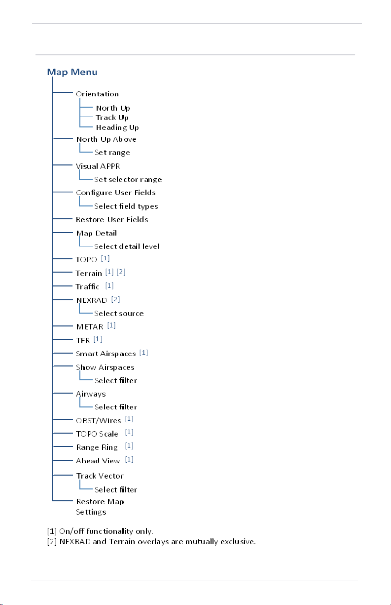
Navigation
3.2 Map Setup
Map setup options allow you to customize
the display of aeronautical information.
Tap Menu when you need to:
• Change map orientation settings
• Configure user fields
• Adjust the map detail level
• Enable map overlays
• Select a NEXRAD source
• Filter airspace data according to
altitude
• Specify airway types and range values
• Expand the forward-looking view for
improved situational awareness
RESTORE MAP SETTINGS
With the exception of user fields, this key
restores all original factory map settings.
3-12 GPS 175/GNX 375 Pilot’s Guide 190-02207-02 Rev. 1
Page 87

3.2.1 Configure User Fields
Navigation
DEFAULT USER FIELDS
• DIS - Distance
• TRK - Track
• GS - Ground Speed
• DTK - Desired Track
Tap any key and select from the list of available data types.
Displayed units change based on selection.
Displays the Map page in configuration
mode, allowing you to customize the
display of data in each corner of the
Map page.
User fields are useful during time
sensitive and work load intense
phases of flight.
In configuration mode:
• All four data fields change to
selectable keys
• All other map elements are
inactive
Selecting “OFF” removes the
corresponding user field from the
map page.
User Field
Absent
Tapping Restore User Fields returns all fields to their default settings.
190-02207-02 Rev. 1 GPS 175/GNX 375 Pilot’s Guide 3-13
Page 88

Navigation
LABEL FIELD TYPE LABEL FIELD TYPE
BRG Bearing to waypoint MSA Minimum safe altitude
DIS/BRG
APT
DIS Distance to waypoint OAT (total)
DIS to Dest
DTK Desired track
ESA En route safe altitude TKE Track angle error
ETA Estimated time of arrival Trip Timer Timer display
ETA at Dest ETA at destination TRK Track
ETE Estimated time en route VSR Vertical speed required
ETE to Dest ETE to destination Wind Wind speed and direction
Generic
Timer
GS GPS ground speed OFF Do not display data field
GSL GPS altitude
Distance/bearing from
destination airport (i.e.,
the straight line distance)
Distance to destination
(i.e., the distance along
the flight plan)
Timer display XTK Cross track error
OAT (static)
Time Current time
Time to
TOD
Outside static air
temperature
Outside total air
temperature
Time to top of descent
“Destination” refers to the missed approach point (if an approach is loaded) or
the final airport in the flight plan.
3.2.2 Map Orientation
Sets the orientation of the map display.
Options include North Up, Track Up, or Heading Up.
Label below the North indicator shows the current orientation.
This label is absent when the info banner is active.
North Up is useful when zoomed out to view the entire route or a frontal system
on a NEXRAD display.
3-14 GPS 175/GNX 375 Pilot’s Guide 190-02207-02 Rev. 1
Page 89

Navigation
3.2.3 North Up Above
Sets the range at which map orientation changes to North Up.
Using the North Up Above feature causes the screen to switch at certain zoom
levels. This is useful as a shortcut to quickly increase situational awareness.
3.2.4 Visual Approach
Sets the distance from the
destination airport at which the
Visual Approach selector key
becomes active.
Visual Approach
Key
To reduce page clutter, the key moves to the upper
left corner of the display when the info banner is
active.
3.2.5 TOPO Scale
Displays a topographical elevation
scale.
190-02207-02 Rev. 1 GPS 175/GNX 375 Pilot’s Guide 3-15
Page 90

Navigation
3.2.6 Range Ring
3.2.7 Track Vector
FEATURE LIMITATIONS
• Indication absent when aircraft velocity is < 30 kt
Provides a more precise indication
of distance between the aircraft
and map objects.
Indicates the current ground track.
Arrow tip represents aircraft position
at the specified time interval
(if the aircraft maintains current
ground track during that time).
Track vector length options display as a dashed line and arrow extending from
the aircraft icon, showing current track and distance the aircraft will travel in the
selected time.
If the track vector is placed over a point on the map, and no data is entered into
the system, the unit indicates a wind-corrected GPS track to that point. This is
useful for intercepting airways and radials, making small but positive lateral
corrections during approaches, and in setting up for arrivals in the terminal area.
3.2.8 Ahead View
FEATURE LIMITATIONS
• Not available when page orientation is North Up
Repositions ownship near the
bottom of the page to expand the
view ahead.
3-16 GPS 175/GNX 375 Pilot’s Guide 190-02207-02 Rev. 1
Page 91
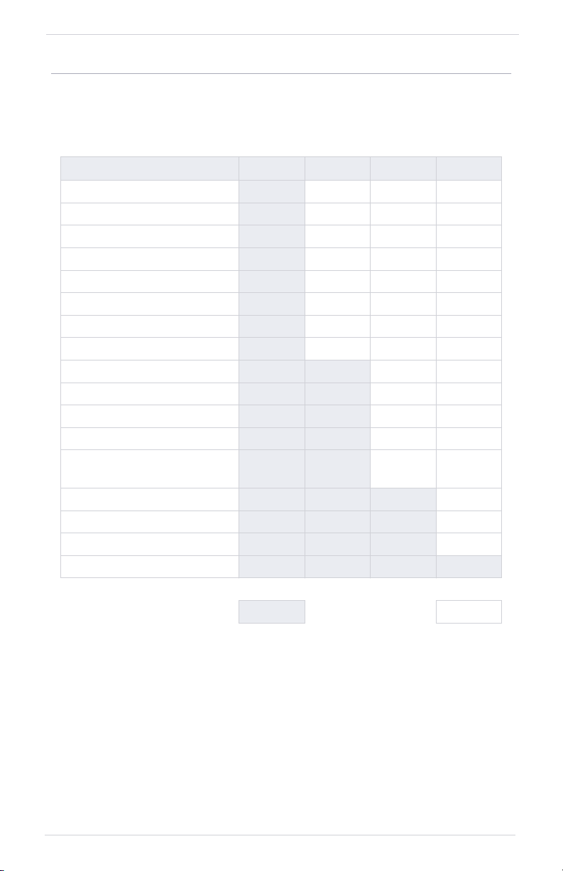
3.2.9 Map Detail
Changes to the map detail level take effect immediately. Options include:
• Full • High • Medium • Low
FEATURE FULL HIGH MEDIUM LOW
Small Cities
Medium Cities
Large Cities
Freeways
Highways
Roads
Railroads
Basemap Labels
VORs
NDBs
Line Obstacles
Point Obstacles
Airspaces that are not
prohibited or restricted
Waypoints
SafeTaxi
Restricted Airspaces
Prohibited Airspaces
Navigation
Present Removed
190-02207-02 Rev. 1 GPS 175/GNX 375 Pilot’s Guide 3-17
Page 92
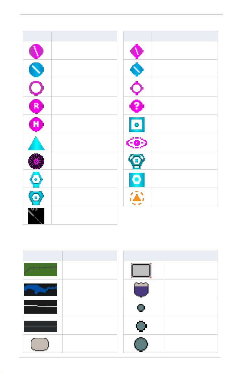
Navigation
AVIATION DATA SYMBOLS
SYMBOL DESCRIPTION SYMBOL DESCRIPTION
Non-towered,
non-serviced airport [1]
Towered, non-serviced
airport [1]
Soft surface, non-serviced
airport
Restricted (private) airport Unknown airport
Heliport ILS/DME or DME only
Intersection LOM
NDB TACAN
VOR VOR/DME
VORTAC VRP
Runway extension
Non-towered, serviced
airport [1]
Towered, serviced airport
[1]
Soft surface, serviced
airport
[1]Symbol depicts orientation of longest runway.
LAND DATA SYMBOLS
SYMBOL DESCRIPTION SYMBOL DESCRIPTION
Railroad National Highway
River/Lake Freeway
State/Province Border Small City
Local Road Medium City
Local Highway Large City
3-18 GPS 175/GNX 375 Pilot’s Guide 190-02207-02 Rev. 1
Page 93

3.3 Map Overlays
Navigation
OVERLAY SELECTIONS
• TOPO
• Terrain
• Traffic
• NEXRAD
• METAR
• TFR
• Airspaces
• Airways
• Obstacles &
Wires
3.3.1 Overlay Controls
Control keys enable the specified overlay function only and
do not activate interfaced equipment. Control keys remain
active even in the absence of required data.
Overlay controls reside in the Map menu.
TOPO
Overlay data controls reside in the
Map menu. Changes to an overlay
setting take effect immediately.
NEXRAD and Terrain overlays are
mutually exclusive. Enabling one
automatically disables the other.
NEXRAD and Traffic overlays are
optional.
• Overlays topographical data
and ground elevation scale
• Depictions are similar to a VFR
sectional
• Pilot-selectable topographical
elevation scale available
TERRAIN
• Overlays terrain map data
• Color shading depicts terrain
elevation relative to the
aircraft’s altitude
190-02207-02 Rev. 1 GPS 175/GNX 375 Pilot’s Guide 3-19
Page 94

Navigation
TRAFFIC
NEXRAD
METAR
• Overlays traffic information
• Filter selection on the Traffic
page determines altitude range
• Feature optional for GPS 175
• Overlays datalink precipitation
weather information
• Options include: CONUS,
Regional, or off (none)
• Feature optional for GPS 175
• Overlays graphical METARs
• Tapping flag icon displays
information on current and
forecast conditions
• Available only in areas covered
by the active navigation
database
• Feature optional for GPS 175
TFR
• Overlays graphical TFRs
• Tapping this airspace symbol
displays details regarding the
restricted area
• Feature optional for GPS 175
3-20 GPS 175/GNX 375 Pilot’s Guide 190-02207-02 Rev. 1
Page 95

AIRSPACES
AIRWAYS
OBSTACLES & WIRES
Navigation
• Overlays airspace boundaries
with altitude labels
• Filter selection determines
altitude range
• Overlays the selected airway
type(s) with identifier labels
• Options include: low, high, all,
or off (none)
• High altitude airways are green,
low altitude airways are gray
• Overlays obstacle and wire data
• Color shading depicts an
object’s elevation relative to the
aircraft’s altitude
190-02207-02 Rev. 1 GPS 175/GNX 375 Pilot’s Guide 3-21
Page 96
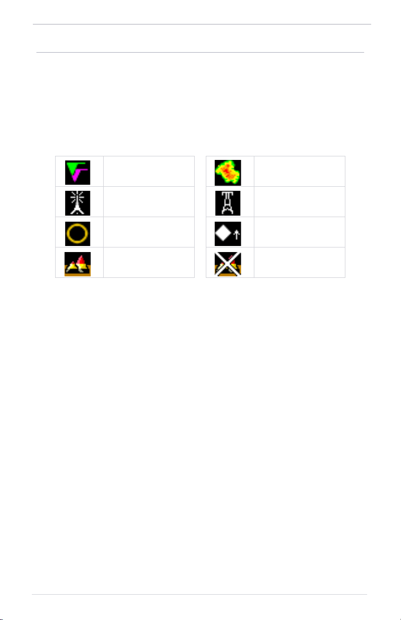
Navigation
3.3.2 Overlay Status Icons
Icons indicate which overlays are present at the current map range. A crossed out
icon means the overlay is active, but data is unavailable due to a failure, test, or
standby condition (where relevant).
The absence of an overlay icon means one of two possible conditions:
1. Overlay not present at the current detail level or zoom setting.
2. Overlay control is off.
METAR NEXRAD
Obstacle Power Line
TFR Traffic
Terrain Data not available
3-22 GPS 175/GNX 375 Pilot’s Guide 190-02207-02 Rev. 1
Page 97

3.3.3 Smart Airspace
Smart Airspace Off
Non-pertinent
Airspace
Smart Airspace On
SMART AIRSPACE CRITERIA
AIRCRAFT ALTITUDE
Sea level >1,000 ft
>10,000 ft 2,000 ft
Navigation
Garmin’s Smart Airspace feature
automatically de-emphasizes
non-pertinent airspace away from
the aircraft’s current altitude.
When an airspace’s vertical
proximity to the aircraft is
>1,000 ft:
• Its boundary becomes
transparent
• All associated altitude labels
turn gray
This range increases linearly to
2,000 ft as the aircraft ascends to
10,000 ft.
AIRSPACE PROXIMITY
TO AIRCRAFT
[1]
[1]Vertical distance above and below aircraft altitude.
AIRSPACE DATA SYMBOLS
SYMBOL DESCRIPTION SYMBOL DESCRIPTION
Class B Altitude
Label (ceiling/floor)
Class C Altitude
Label (ceiling/floor)
Class D Altitude
Label (ceiling only)
TFR MIL
Class B/TMA Other/ADIZ
190-02207-02 Rev. 1 GPS 175/GNX 375 Pilot’s Guide 3-23
Class C/TCA
Class D
Restricted/Prohibited
Page 98

Navigation
3.3.4 SafeTaxi
SAFETAXI FEATURES
• Airport diagram overlay that includes hot spot information
• Aircraft position relative to taxiways, runways, and airport landmarks
• Pilot selectable range options
SafeTaxi provides greater map detail
and higher image resolution at lower
zoom levels.
Feature labels denote:
• Runways
• Taxiways
• Airport landmarks
SAFETAXI DATA SYMBOLS
SYMBOL DESCRIPTION SYMBOL DESCRIPTION
Runway Taxiway
Helipad Construction Area
Airport Beacon Unpaved Parking
3-24 GPS 175/GNX 375 Pilot’s Guide 190-02207-02 Rev. 1
Page 99

HOT SPOTS
Navigation
SafeTaxi hot spots identify locations on an
airport surface where positional confusion
or runway incursions are likely to occur.
These known problem areas require
heightened attention by pilots.
Selecting the border of a hot
spot displays a brief summary of
the indicated hazard and an
information key.
Tapping this key provides additional location information.
Numbering corresponds to a list on the airport diagram.
The following airport features
may be deemed hot spots by
aviation authorities.
• Intersecting taxiways and
runways
• Complex ramp areas
• Directional limitations
• Limited wing-tip clearance
• Overflight risk
CONSTRUCTION SPOTS
There are no expanded detail keys or notes
associated with construction areas.
Construction Area Border
190-02207-02 Rev. 1 GPS 175/GNX 375 Pilot’s Guide 3-25
Page 100

Navigation
Active Flight Plan
Current flight plan information displays as a scrolling list on the
Active Flight Plan page.
FEATURE REQUIREMENTS
• Active flight plan
FEATURE LIMITATIONS
• Displays up to 100 waypoints for an active flight plan
Active Flight Plan Page
1 Waypoint Identifier Column 5 Selectable Data Field Columns
2 Active Leg Indicator 6 Fix Type Indicator
3 Current Waypoint 7 Leg Data
4 Waypoint Type Icon 8 Add Waypoint Key
3-26 GPS 175/GNX 375 Pilot’s Guide 190-02207-02 Rev. 1
 Loading...