

Page 1
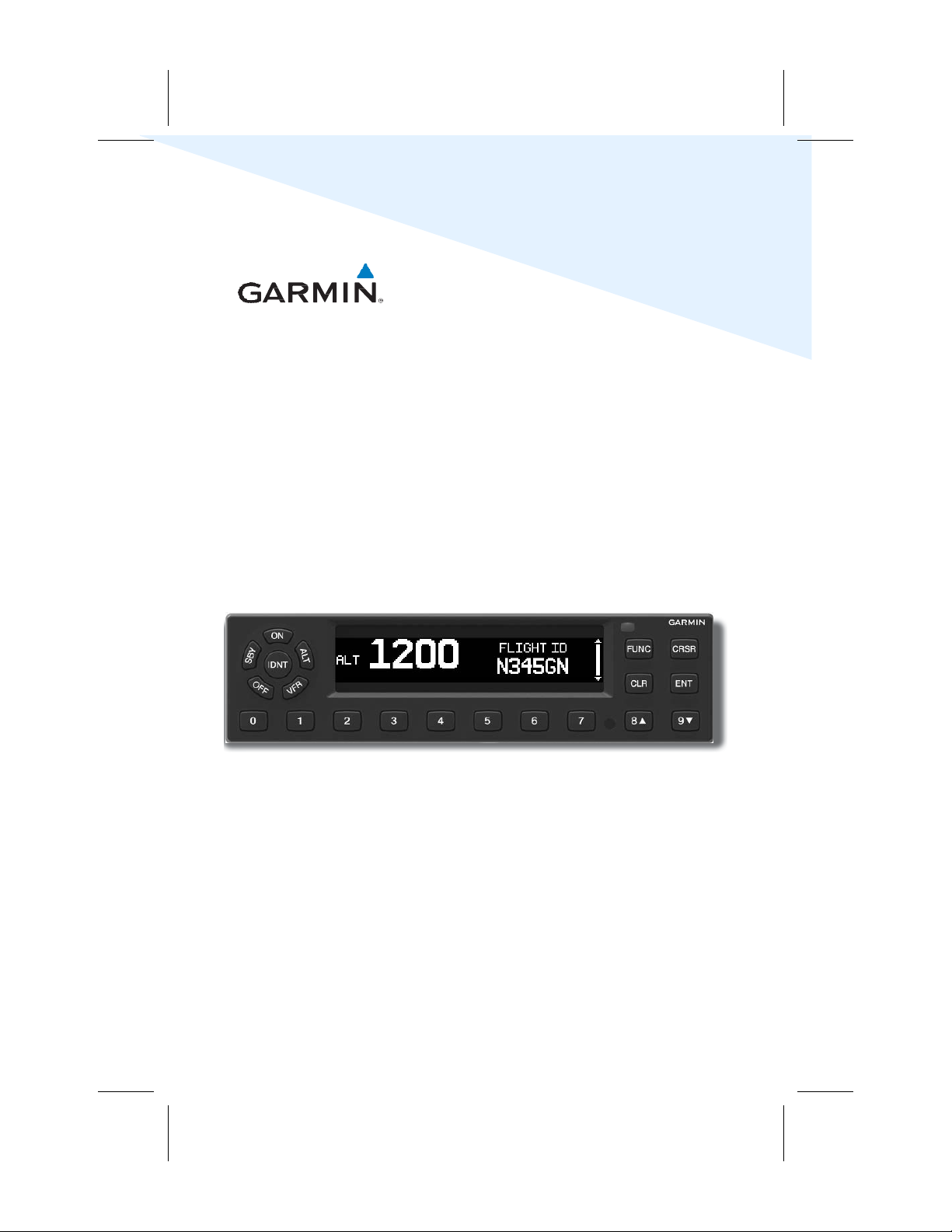
GTX 335/345
All-In-One ADS-B Transponder
Pilot's Guide
Page 2

© 2016-2018 Garmin Ltd. or its subsidiaries. All rights reserved.
This manual reflects the operation of GTX 3X5 transponders.
Except as expressly provided herein, no part of this manual may be reproduced, copied, transmitted, disseminated,
downloaded or stored in any storage medium, for any purpose without the express written permission of Garmin.
Garmin hereby grants permission to download a single copy of this manual and of any revision to this manual onto a
hard drive or other electronic storage medium to be viewed for personal use, provided that such electronic or printed
copy of this manual or revision must contain the complete text of this copyright notice and provided further that any
unauthorized commercial distribution of this manual or any revision hereto is strictly prohibited.
This document complies with Garmin Banned and Restricted Substances document, P/N 001-00211-00.
Bluetooth® word mark and logos are registered trademarks owned by Bluetooth SIG, Inc. and any use of such marks
by Garmin is under license.
For information about the Aviation
Visit flyGarmin.com
for aviation product support.
Limited Warranty refer to Garmin’s website.
Printed in the U.S.A
August 2018 190-01499-00 Rev. E
Page 3

Copyright Information
WARNING
WARNING
WARNING
WARNING
WARNING
WARNING
CAUTION
WARNINGS/CAUTIONS/NOTES
Do not use data link weather information for maneuvering in, near, or around areas of
hazardous weather. Information contained within data link weather products may
not accurately depict current weather conditions.
Do not use the indicated data link weather product age to determine the age of the
weather information shown by the data link weather product. Due to time delays
inherent in gathering and processing weather data for data link transmission, the
weather information shown by the data link weather product may be significantly older
than the indicated weather product age.
This product, its packaging, and its components contain chemicals known to the
State of California to cause cancer, birth defects, or reproductive harm. This
notice is being provided in accordance with California’s Proposition 65. If you have
any questions or would like additional information, please refer to our website at
www.garmin.com/prop65/.
WARNINGS \ CAUTIONS \ NOTES
To reduce the risk of unsafe operation, carefully review and understand all aspects of
the GTX 3X5 Pilot’s Guide. Thoroughly practice basic operation prior to actual use.
The display surface is coated with a special anti-reflective coating that is very
sensitive to skin oils, waxes, and abrasive cleaners. It is very important to clean the
lens using an eyeglass lens cleaner that is specified as safe for anti-reflective
coatings with a clean, lint-free cloth.
Traffic information is provided as an aid in visually acquiring traffic. Pilots must
maneuver the aircraft based only upon ATC guidance or positive visual acquisition
of traffic.
Unauthorized repairs or modifications could result in permanent damage to the
equipment, and void your warranty and your authority to operate this device under
FCC and FAA regulations.
190-01499-00 Rev. E GTX 335/345 Pilot’s Guide i
Page 4
WARNINGS/CAUTIONS/NOTES
NOTE
NOTE
NOTE
The coverage expected for all operations (transponder replies to ATC, ADS-B and FIS-B
reception) from the Garmin GTX 3X5 is limited to line of sight. Low altitude or aircraft
antenna shielding by the aircraft itself may result in reduced range. Range can be
improved by climbing to a higher altitude.
This product does not contain any user-serviceable parts. Repairs should only be
made by an authorized Garmin service center.
WARNINGS \ CAUTIONS \ NOTES
It is the responsibility of the GTX 3X5 owner, residing outside of the U.S., to obtain
proper licensing before using the transponder.
ii GTX 335/345 Pilot’s Guide 190-01499-00 Rev. E
Page 5

PRODUCT REGISTRATION AND SUPPORT
Copyright Information
Product Registration and Support
Help us better support you by completing your online registration. To register, have your
product’s serial number on hand. Visit www.Garmin.com and click the Product
Registration link on the home page. Be sure to record your serial number in the space
provided below.
PRODUCT REGISTRATION AND SUPPORT
Serial Number
This guide is available electronically at: www.garmin.com/manuals
If you have any questions, visit flyGarmin.com
:
Record of Revisions
Part Number Revision Date Description
190-01499-00 A
B
C
D
E
02/12/16
08/12/16
09/09/16
07/11/18
08/02/18
Initial release.
Added rotorcraft information.
Minor edits.
Added FIS-B information.
Minor edits.
190-01499-00 Rev. E GTX 335/345 Pilot’s Guide iii
Page 6

SOURCES AND REFERENCES
INTRODUCTION
Abbreviations and Acronyms
ADS-B
ADS-R
AHRS
ATC
ATCRBS
BLE
FIS-B
ABBREVIATIONS AND ACRONYMS
PED
PIREP
SSR
TAS
TCAS
TFRs
TIS
TIS-B
Automatic Dependant Surveillance-Broadcast
Automatic Dependent Surveillance-Rebroadcast
Attitude and Heading Reference System
Air Traffic Control
Air Traffic Control Radar Beacon System
Bluetooth Low Energy
Flight Information Services-Broadcast
Portable Electronic Device
Pilot Report
Secondary Surveillance RADAR
Traffic Advisory System
Traffic Collision Avoidance System
Temporary Flight Restrictions
Traffic Information Service
Traffic Information Service-Broadcast
Sources and References
Automatic Dependent Surveillance–Broadcast (ADS-B) is an important part of the FAA's
NextGEN effort. ADS-B is a precise GPS-based surveillance system that provides ATC
access to traffic data well beyond the capabilities of RADAR alone. It enables the display of
precise traffic data in cockpits equipped to receive ADS-B.
For more information about ADS-B, visit the Garmin ADS-B Academy website.
www.garmin.com/us/intheair/ads-b/
For more information about ADS-B and other NextGEN programs, visit the FAA NextGEN
website. www.faa.gov/nextgen/
iv GTX 335/345 Pilot’s Guide 190-01499-00 Rev. E
Page 7

Copyright Information
1 GTX 3X5 Series Transponders ....................................................................................... 1-1
1.1 GTX 335 Transponder ................................................................................................... 1-1
1.2 GTX 345 Transponder ................................................................................................... 1-1
2 GTX 3X5 Controls ........................................................................................................... 2-1
2.1 Panel Mount Transponder Controls ............................................................................... 2-1
2.2 Mode Selection Keys ..................................................................................................... 2-1
2.3 Squawk Code Keys ....................................................................................................... 2-3
2.4 Function Keys ................................................................................................................ 2-4
2.5 Remote Transponder Control ........................................................................................ 2-4
3 Display Functions and Settings ..................................................................................... 3-1
3.1 Transponder (XPDR) ...................................................................................................... 3-1
3.2 Timers (TMR) ................................................................................................................. 3-2
3.3 Altitude (ALT) ................................................................................................................ 3-3
3.4 System (SYS) ................................................................................................................. 3-4
3.4.1 Bluetooth Pairing Instructions ............................................................................... 3-5
3.4.2 Bluetooth Paired Device Information ..................................................................... 3-5
4 ADS-B IN Traffic (GTX 345 Only) .................................................................................... 4-1
4.1 Traffic Alerting .............................................................................................................. 4-2
4.2 Helicopter Traffic Alerting ............................................................................................. 4-2
4.2.1 On Scene Mode .................................................................................................... 4-2
4.2.2 No Source of Heading Data .................................................................................. 4-3
4.3 TCAD/TAS/TCAS I GTX 345 Integration ......................................................................... 4-3
5 FIS-B Weather and Flight Information .......................................................................... 5-1
6 Connext Bluetooth ......................................................................................................... 6-1
7 Troubleshooting ............................................................................................................. 7-1
7.1 Transponder Failures ..................................................................................................... 7-1
7.2 Transponder System Messages ...................................................................................... 7-2
List of Figures
Figure 2-1 Squawk Code Entry Field ..................................................................................... 2-3
Figure 3-1 Flight ID Edit Display Page .................................................................................... 3-1
Figure 3-2 Flight ID Editable Display Page ............................................................................. 3-1
Figure 3-3 Bluetooth Page ..................................................................................................... 3-5
Figure 3-4 Bluetooth Pair Request Page ................................................................................ 3-5
Figure 3-5 Paired Device List Page ......................................................................................... 3-5
Figure 3-6 Auto-reconnect Page ........................................................................................... 3-5
Figure 3-7 Unpair Device? Page ............................................................................................ 3-6
Figure 3-8 (Selected) Bluetooth Device Name Page ............................................................... 3-6
Figure 7-1 ADS-B 1090 Failed Screen .................................................................................... 7-1
Figure 7-2 ADS-B 1090 and Transponder Failed Screen ......................................................... 7-1
List of Tables
Table 2-1 Mode Section Key Functions ................................................................................ 2-2
Table 2-2 Squawk Code Key Functions ................................................................................ 2-3
Table 2-3 Squawk Codes ..................................................................................................... 2-3
Table 2-4 Function Keys ...................................................................................................... 2-4
Table 5-1 FIS-B Weather Products ........................................................................................ 5-2
Table 6-1 GTX 345 Connext Features .................................................................................. 6-1
Table 7-1 Troubleshooting .................................................................................................. 7-2
TABLE OF CONTENTS
190-01499-00 Rev. E GTX 335/345 Pilot’s Guide v
Page 8

COPYRIGHT INFORMATION
This page intentionally left blank.
vi GTX 335/345 Pilot’s Guide 190-01499-00 Rev. E
Page 9

1 – GTX 3X5 SERIES XPDR
GTX 3X5 XPDR
1 GTX 3X5 SERIES TRANSPONDERS
The GTX 3X5 Series Transponders are panel mount and remote transponders. Both
models are TSO-C112e (Level 2ens, Class 1) compliant mode S transponders with
TSO-C166b compliant ADS-B Out 1090 MHz Extended Squitter functionality.
1.1 GTX 335 Transponder
GTX 335 Features:
• ADS-B Out
• TIS traffic display output and aural alerting
• Altitude deviation alerting
• Timers: count up, count down, flight, trip
• Static (Outside) air temperature display
• Density and pressure altitude display
• Internal GPS (Optional)
For more information on TIS traffic refer to the display’s operator’s manual and the FAA
Aeronautical Information Manual (AIM), 4-1-17.
1.2 GTX 345 Transponder
The GTX 345 includes ADS-B In functionality, when connected to a suitable display.
GTX 345 Features:
• ADS-B Out
• Dual-band ADS-B In traffic display output and aural alerting
• Integration with TCAD/TAS/TCAS I traffic systems
• FIS-B weather and flight information display output
• Bluetooth interface provides traffic, FIS-B, and other air data to a Portable Elec
Device (PED)
• Altitude deviation alerting
• Timers: count up, count down, flight, trip
• Static (Outside) air temperature display
• Density and pressure altitude display
• Internal GPS (Optional)
tronic
1 - GTX 3X5 SERIES XPDR
190-01499-00 Rev. E GTX 335/345 Pilot’s Guide 1-1
Page 10

1 – GTX 3X5 SERIES XPDR
This page intentionally left blank.
1-2 GTX 335/345 Pilot’s Guide 190-01499-00 Rev. E
Page 11

1 – GTX 3X5 SERIES XPDR
NOTE
GTX 3X5 XPDR
2 GTX 3X5 CONTROLS
2.1 Panel Mount Transponder Controls
The GTX 3X5 series transponders have an auto-dimming display and keypad layout. The
keys access the transponder’s controls and features.
ON
Powers on, disables altitude reporting.
ALT
Powers on, enables altitude reporting.
VFR
Changes to the preprogrammed squawk code for VFR.
OFF
Powers off.
SBY
Powers on or changes into standby mode.
IDNT
Activates the Ident function.
2.2 Mode Selection Keys
2 - GTX 3X5 CONTROLS
The transponder system no longer supports a pilot selectable GND mode. The
transponder should always be in ALT mode prior to moving on the airport surface.
It must be in ALT mode when operating in certain controlled airspace, in
accordance with 14 CFR 91.215. For guidance on transponder operation, refer to
the FAA Aeronautical Information Manual (AIM), 4-1-20(a)(3).
When on the ground or in the air always operate the transponder in ALT mode, unless
otherwise requested by ATC. It is acceptable to go directly from OFF to ALT mode. It is not
necessary to place in SBY mode for a “warm up” period. The transponder automatically
determines whether the aircraft is in the air or on the ground and sends that information
to other aircraft and ATC.
Automatic ALT Mode Switching
If the unit is configured for Automated Airborne Determination and senses a transition
from on ground to in air, the unit automatically switches from SBY to ALT mode.
190-01499-00 Rev. E GTX 335/345 Pilot’s Guide 2-1
Page 12
◦
ON
ALT
2 - GTX 3X5 CONTROLS
VFR
IDENT
SBY
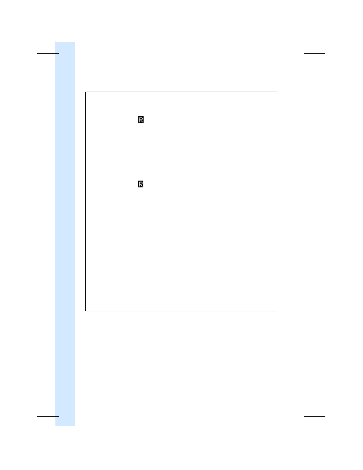
The ON key selects the on mode.
◦
The transponder replies to interrogations.Replies do not include pressure
altitude.
◦
The Reply ( ) symbol on the display indicates the transponder is
responding.
◦
The
ALT
key selects the alt mode.
◦
Always use Alt mode while
otherwise requested by ATC.
◦
All aircraft air/ground state transmissions are handled via the GTX 3X5
transponder and require no pilot action.
◦
The transponder replies to identification and altitude interrogations.
◦
The Reply ( ) symbol indicates the transponder is responding.
◦
The GTX 3X5 transmissions include pressure altitude.
◦
The
VFR
key sets the transponder code to the preprogrammed VFR
code.This is factory set to 1200, but.may be changed during installation
configuration.
◦
To restore the previous identification code, press the
◦
To toggle between these two codes, continue to press the
◦
The
IDENT
transponder apart from others on the air traffic controller’s screen.
◦
During this time the word “IDENT” will appear in the upper left corner of
the display.
◦
The
SBY
key selects the standby mode.
◦
The transponder will not reply to any interrogations or transmit ADS-B Out.
◦
If BT functions are enabled, BT functionality remains operational.
◦
The GTX 345 will continue to receive ADS-B In information, but will not be a
TIS-B participant.
Table 2-1 Mode Section Key Functions
in the air and on the ground
key activates the IDENT function for 18 seconds. This sets the
, unless
VFR
key a second time.
VFR
key.
2-2 GTX 335/345 Pilot’s Guide 190-01499-00 Rev. E
Page 13
1 – GTX 3X5 SERIES XPDR
GTX 3X5 XPDR
2.3 Squawk Code Keys
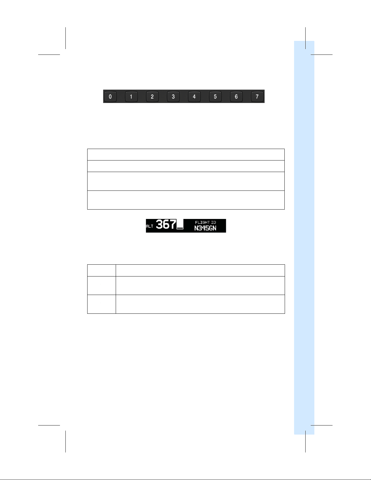
There are eight squawk code entry keys (0 – 7). They provide access to all ATCRBS codes.
Pressing one of the squawk code entry keys begins the code selection sequence. Digits
that are not yet entered appear as underscored blanks. When the fourth digit is entered
the new code is activated.
Table 2-2 Squawk Code Key Functions
2 - GTX 3X5 CONTROLS
Press the
Press and hold the
Pressing the
the code entry, retaining the last code entered.
P
ressing the
entry. The last code entered is retained.
7600 Enter code if there is a loss of communication. “LOST COMM” displays
7700
CLR
key to move the cursor back to the previous digit.
CLR
key to move the cursor back to the
CLR
key when the cursor is on the first digit removes the cursor and cancels
CRSR
key when entering the code removes the cursor and cancels the code
Figure 2-1
Code Description
under the squawk field.
Enter code if there is a general emergency. “EMERGENCY” displays under
the squawk field.
Squawk Code Entry
Table 2-3 Squawk Codes
first digit
Field
.
190-01499-00 Rev. E GTX 335/345 Pilot’s Guide 2-3
Page 14

2.4 Function Keys
Table 2-4 Function Keys
FUNC
ENT
CRSR
2 - GTX 3X5 CONTROLS
CLR
8
9
The
FUNC
key cycles through four menu groups shown on the right-hand side
of the display. Menu groups include:
◦
Transponder (XPDR)
◦
Timers (TMR)
◦
Altitude (ALT)
◦
System (SYS)
The
ENT
key acknowledges the selection of menu items and pilot data entry
fields.
The
CRSR
key activates the cursor to select items in menus and on pages.
The
CLR
key clears selected entry and exits the menus.
The key enters the number eight in the Flight ID or Count Down timer.
It navigates up
The key enters the number nine in the Flight ID or Count Down timer.
It navigates down and between the functions and settings within a menu
group.
and between the functions and settings within a menu group.
2.5 Remote Transponder Control
The GTX 3X5 transponder functions are controllable from connected, Garmin certified
displays (e.g., GTN) or G1000 integrated flight deck. When the GTX 3X5 is installed in a
location other than the cockpit instrument panel, remote control from a display is the only
GTX 3X5 flight crew interface available.
Remote transponder control includes:
◦
Squawk code
◦
IDENT
◦
Transponder mode
◦
ADS-B transmit control*
◦
Flight ID*
*When allowed by installation configuration.
Refer to the display's pilot guide for transponder control operation that is specific to each
display.
2-4 GTX 335/345 Pilot’s Guide 190-01499-00 Rev. E
◦
TIS traffic enable/disable (GTX 335 only)
Page 15
1 – GTX 3X5 SERIES XPDR
Press
FUNC
key
Press
FUNC
key
Press
FUNC
key
Press
FUNC
key
GTX 3X5 XPDR
3 DISPLAY FUNCTIONS AND SETTINGS
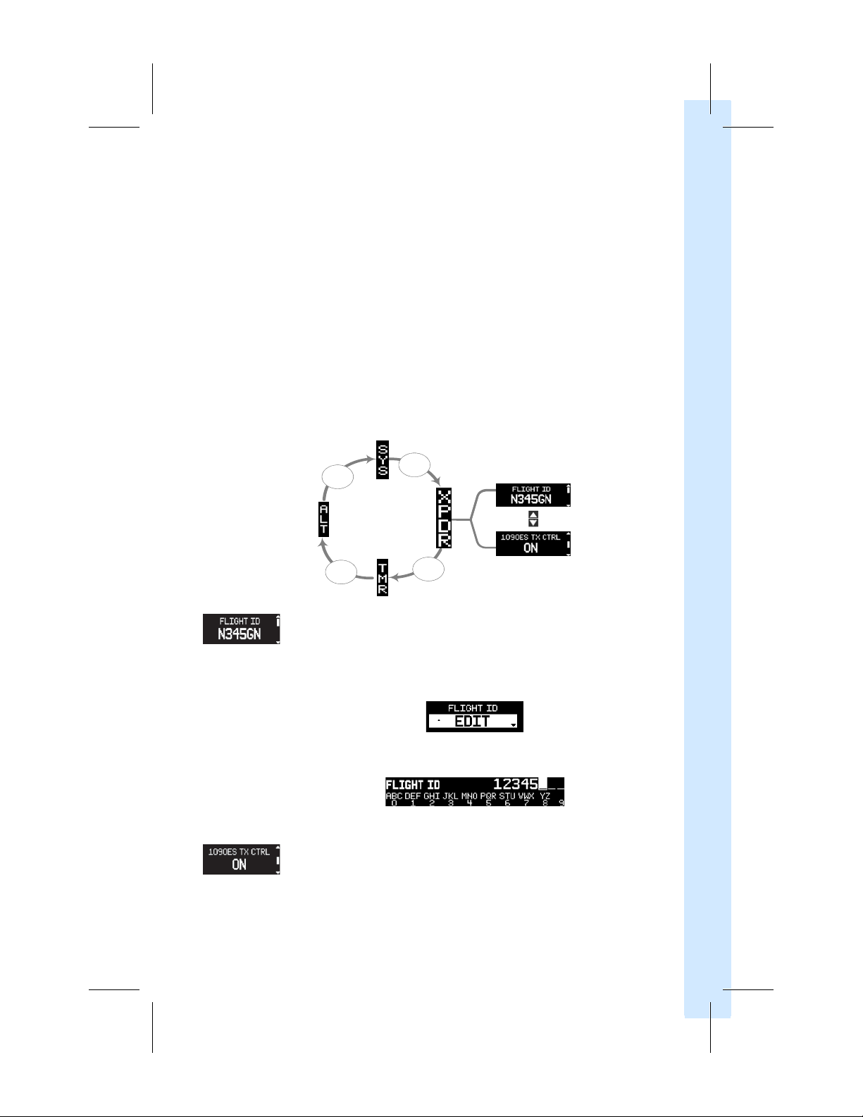
The GTX 3X5 is organized into four menu groups shown on the right-hand side of the
display. Each menu group contains a set of functions and settings. Menu groups include:
◦
Transponder (XPDR)
1. To navigate between the menu groups, press the
2. To navigate up or down and between the functions and settings within a current
menu group, press the
When enabled by installation configuration, the menu group last selected and the
functions last used within that menu group are saved and restored at system power on.
Otherwise, function navigation resets to the default state at system power on.
3.1
Transponder
◦
Timers (TMR)
8
(XPDR)
or
9
keys.
◦
Altitude (ALT)
FUNC
key.
◦
System (SYS)
3 - DISPLAY FUNCTIONS AND SETTINGS
FLIGHT ID – This page displays the active Flight ID. Unless configured, the
Flight ID is not editable. If configured, the Flight ID Edit prompt displays,
ENT
and
CLR
as shown in figure 3-1. To edit the Flight ID use the
For an example of the editable Flight ID page refer to
figure 3-2.
keys.
Figure 3-1 Flight ID Edit Display Page
Figure 3-2 Flight ID Editable Display Page
1090ES TX CTRL
– This page displays the current ON/OFF state of the
1090ES ADS-B Out function. Access to pilot control of the 1090ES
ADS-B Out function is through this page when allowed by system
configuration.
190-01499-00 Rev. E GTX 335/345 Pilot’s Guide 3-1
Page 16
3.2 Timers (TMR)
Press
FUNC
key
Press
FUNC
key
Press
FUNC
key
Press
FUNC
key
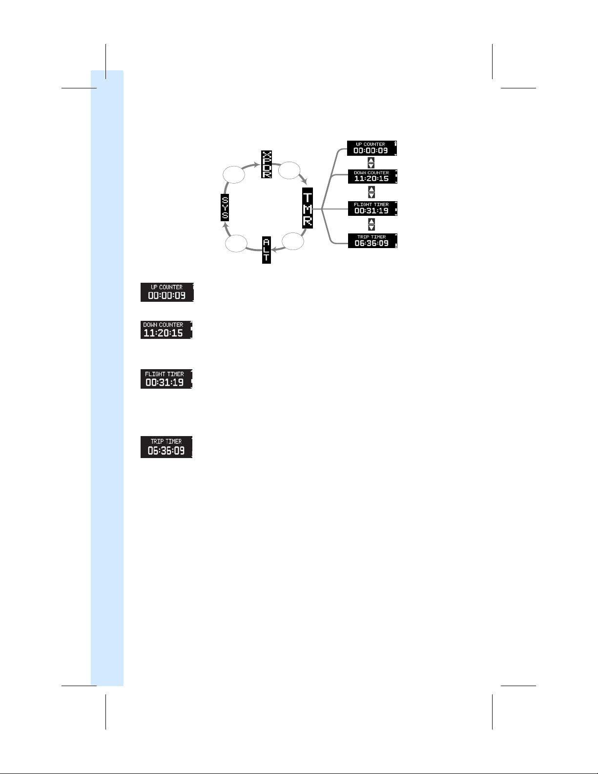
UP COUNTER – This page provides a stopwatch style counter. Manual
start/stop/reset controls are via the
ENT
and
CLR
keys.
DOWN COUNTER
– This page provides notification in a count down style
timer when the timer expires. Manual start/stop/set/reset controls are via
ENT
and
CLR
the
3 - DISPLAY FUNCTIONS AND SETTINGS
FLIGHT TIMER – This page provides an airborne flight timer that
automatically starts and stops with the GTX automatic airborne
keys.
determination. The timer measures the elapsed airborne time since the
last on ground-to-airborne transition. Manual start/stop/reset controls
ENT
and
CLR
are via the
keys.
TRIP TIMER – This page provides an airborne flight timer that
au tomatically starts and stops with the GTX automatic airborne
determination. The timer measures the elapsed airborne time since the
last manual reset of the timer. Manual start/stop/reset controls are via the
ENT
and
CLR
keys.
3-2 GTX 335/345 Pilot’s Guide 190-01499-00 Rev. E
Page 17
3.3
Press
FUNC
key
Press
FUNC
key
Press
FUNC
key
Press
FUNC
key
Altitude
(ALT)
1 – GTX 3X5 SERIES XPDR
GTX 3X5 XPDR
3 - DISPLAY FUNCTIONS AND SETTINGS
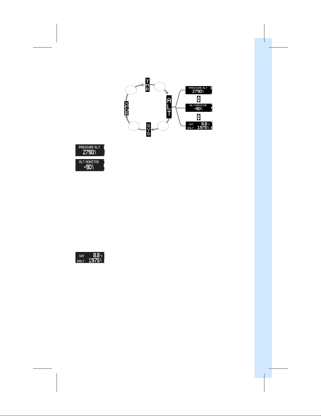
PRESSURE ALT
– This page displays the current pressure altitude.
ALT MONITOR – This page displays the current altitude deviation from
the altitude chosen to maintain. When the altitude monitor is turned on it is
automatically set to the current altitude.
Example: If the monitor is turned on at 9,500 ft, the monitor will trip
when at 9,250 ft. or 9,750 ft., unless the installer configured the
deviation limit to something other than the default value of 250 ft.
If deviation is greater than the deviation limit (default is 250 ft.), the GTX
will display “LEAVING ALTITUDE” for two seconds. It will then switch to
the altitude monitor page. If the altitude alert is configured to
“Message” or “Message + Chime,” the GTX will aurally alert “leaving
altitude.” The GTX will reset the monitor when the aircraft’s altitude
returns within the deviation limit.
CRSR
and
ENT
ON/OFF controls are via the
keys.
SAT/DALT – This page displays the current static air temperature (SAT) and
density altitude (DALT), when available.
190-01499-00 Rev. E GTX 335/345 Pilot’s Guide 3-3
Page 18
3.4 System (SYS)
NOTE
Press
FUNC
key
Press
FUNC
key
Press
FUNC
key
Press
FUNC
key
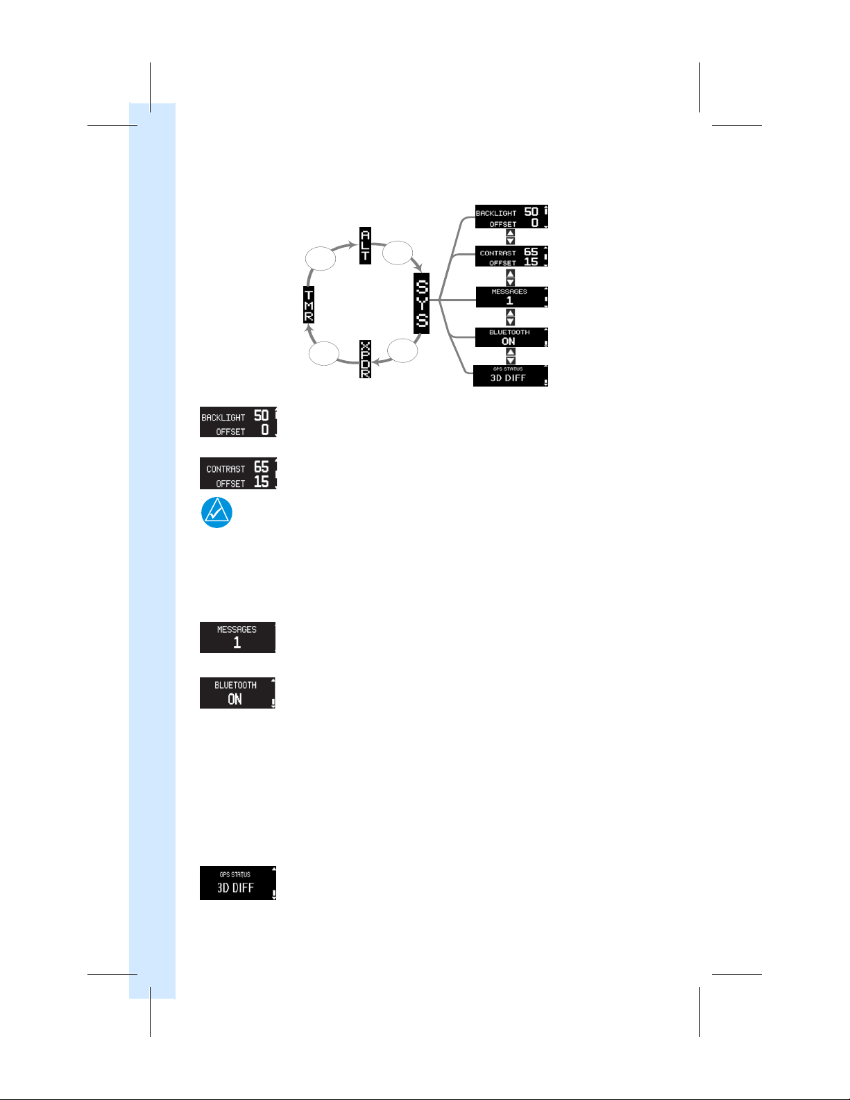
BACKLIGHT –
This page displays the current backlight level and backlight level
offset. The backlight level offset is via the
CONTRAST –
This page displays the current contrast level and contrast level
offset. The contrast level offset is via the
3 - DISPLAY FUNCTIONS AND SETTINGS
Messages are not high priority. Their purpose is to provide additional
information on abnormal system behavior. They do not require immediate pilot
action. Any transponder failure will immediately display an alert with no pilot
action necessary to view the alert. For troubleshooting failure messages, refer
to section 7.
MESSAGES – This page displays the number of active system messages.
Viewing active system messages is via the
BLUETOOTH (GTX 345) –
This page displays the status of the GTX 345
Bluetooth function. This page will not display when the GTX 345 connects to
a GX000 or GTN over HSDB. The Bluetooth function is automatically placed
into pairing mode when this page is displayed. Pairing must be initiated by
the PED and then confirmed on the GTX 345. The last 13 paired PEDs and 6
Bluetooth Low Energy (BLE) devices are saved. At system power on, the GTX
345 automatically connects to any available and previously saved paired PEDs.
PEDs that are currently connected and paired are viewed/deleted via the
8 and
and
9
keys. For instructions on Bluetooth pairing refer to
section 3.4.1. For information on Connext Bluetooth features, refer to
section 6.
GPS STATUS –
This page displays the status of all configured GPS sources. The
GPS position fix details are viewed via
CRSR
and 8
CRSR
and 8
CRSR
CRSR
key selection.
and
9
and
9
key selection.
keys
keys.
.
CRSR
3-4 GTX 335/345 Pilot’s Guide 190-01499-00 Rev. E
Page 19
1 – GTX 3X5 SERIES XPDR
GTX 3X5 XPDR
3.4.1 Bluetooth Pairing Instructions
For first time activation of Bluetooth devices:
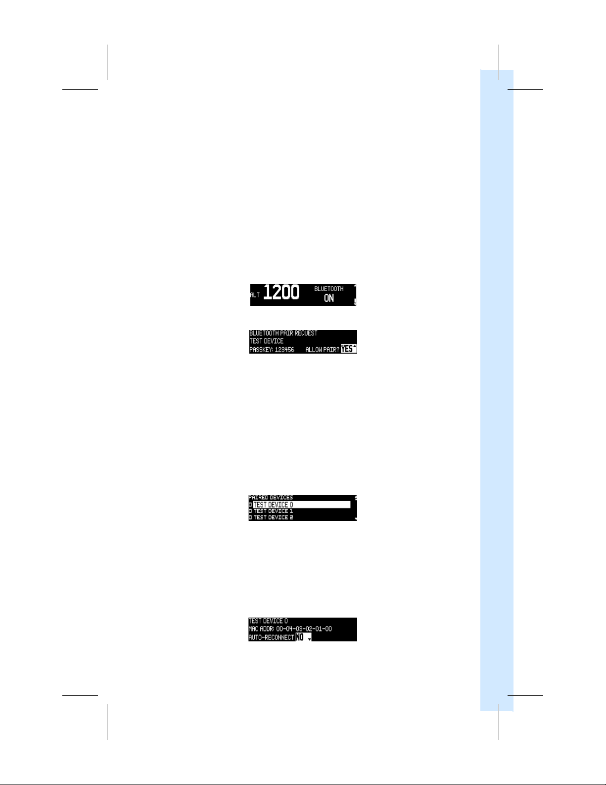
1. Go to the GTX 345 Bluetooth page to enable pairing mode. Refer to figure 3-3. If
connected to a GTN or GX000 via HSDB, refer to the display’s pilot’s guide.
Enable Bluetooth on the PED.
2.
3. Select “GTX 345” from the list of available devices on the PED. Refer to
manufacturer’s information for pairing instructions.
4. When a PED sends a pairing request the Bluetooth Pair Request page will display
the device name and passkey. Refer to figure 3-4.
Press
ENT
5.
on the GTX 345 and accept the pairing request on PED.
Figure 3-3 Bluetooth Page
Figure 3-4 Bluetooth Pair Request Page
3.4.2 Bluetooth Paired Device Information
3 - DISPLAY FUNCTIONS AND SETTINGS
To view the paired device list:
CRSR
1. Press the
To view the menu and pairing status:
1. Press the
2. Then press the
The Paired Devices list page will display. Refer to figure 3-5.
More information about each paired device and applicable settings can be found by doing
the following steps:
To set the auto-reconnect status:
1. Highlight the paired device.
2. Then press
190-01499-00 Rev. E GTX 335/345 Pilot’s Guide 3-5
key.
8 and
9
keys, respectively.
ENT
key.
Figure 3-5 Paired Device List Page
ENT
key. Refer to figure 3-6.
Figure 3-6 Auto-reconnect Page
Page 20
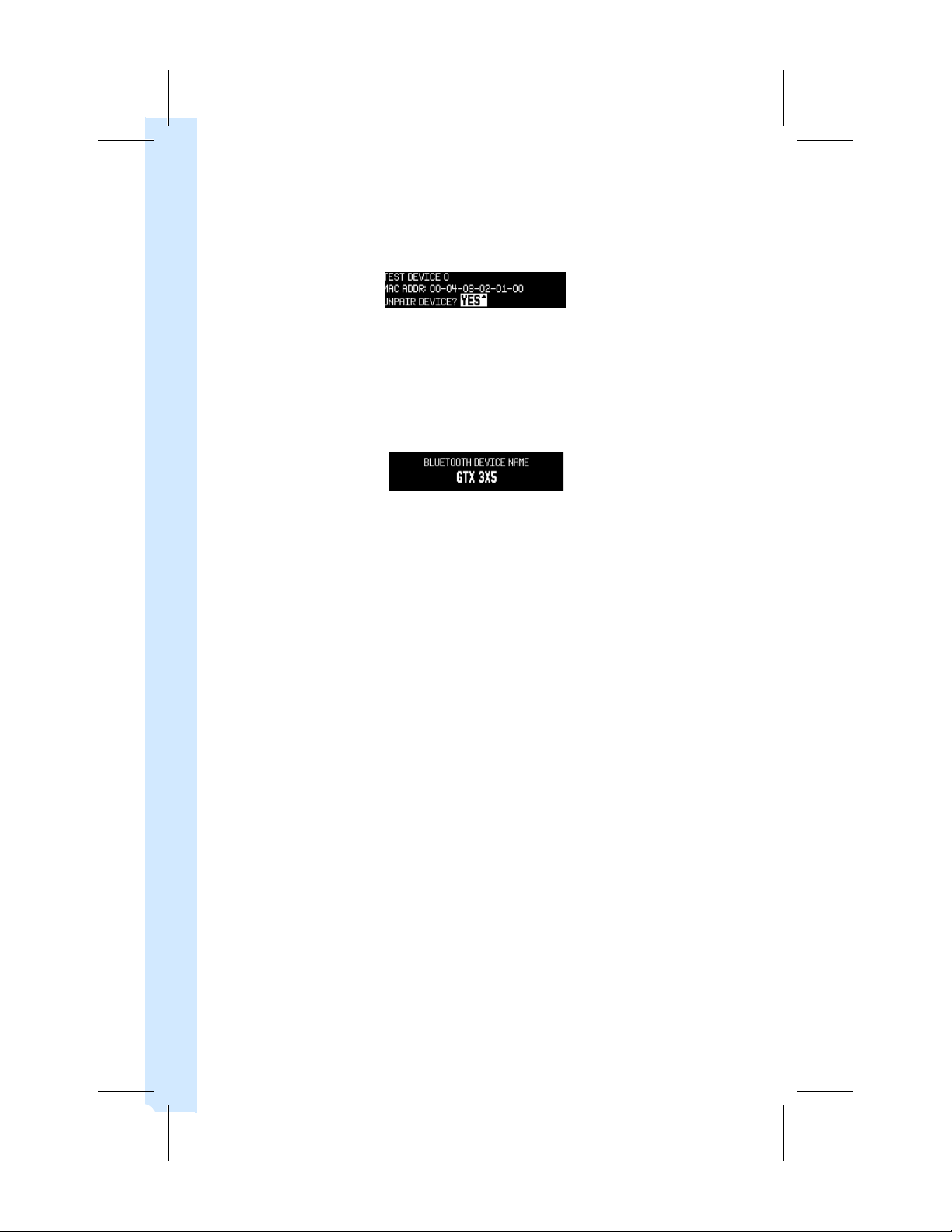
To unpair a device:
1. Highlight the device to be unpaired.
ENT
2. Then press the
To view the device name on the Bluetooth page:
1. Press the
ENT
key. Refer to figure 3-7.
Figure 3-7 Unpair Device? Page
key.
2. Use the
3. Then press the
8 and
9
keys, highlight the device’s name to view.
ENT
key. Refer to figure 3-8.
Figure 3-8 (Selected) Bluetooth Device Name Page
3 - DISPLAY FUNCTIONS AND SETTINGS
3-6 GTX 335/345 Pilot’s Guide 190-01499-00 Rev. E
Page 21
1 – GTX 3X5 SERIES XPDR
NOTE
NOTE
GTX 3X5 XPDR
4 ADS-B IN TRAFFIC (GTX 345 ONLY)
Inherent inaccuracies exist in TIS-B and TAS/TCAS traffic position data. Because
of this the GTX 345 may at times be unable to correlate targets from multiple
sources for the same aircraft. When this occurs, a single aircraft is tracked and
displayed as two co-located targets.
The GTX 345 will continue to receive ADS-B In information when in standby
mode.
The GTX has two modes:
1. Airborne Situational Awareness (AIRB). AIRB is in operation in the en route
environment, outside of five NM from, and 1,500 feet above, the nearest airport.
2. Surface Situation Awareness (SURF). SURF is in operation within the terminal
environment, within five NM and less than 1,500 feet above field elevation. When
SURF is running airport map data and ground targets may be displayed as an aid
to situational awareness.
4 - ADS-B IN TRAFFIC
ADS-B:
ADS-R:
TIS-B:
The GTX 345 receives ADS-B traffic data (ADS-B, ADS-R, TIS-B) through the UAT
(978 MHz) and the 1090 MHz receivers. The GTX 345 may also receive traffic data from
configured TAS/TCAS/TCAD. Traffic data is received, processed, and outputted to a
connected display without pilot interaction. Traffic data may also be displayed on a PED
(e.g., tablet) via the built-in Bluetooth interface or connected Flight Stream 110/210.
Data transmitted directly from other aircraft.
Ground station rebroadcast of ADS-B data after data link translation (UAT to
1090 MHz or 1090 MHz to UAT). This function aids aircrafts only
operating one frequency.
For more information about ADS-B refer to the FAA Aeronautical
Information Manual (AIM), 4-5-7.
Ground station broadcast of secondary surveillance radar (SSR) derived traffic.
190-01499-00 Rev. E GTX 335/345 Pilot’s Guide 4-1
Page 22

4.1 Traffic Alerting
To enhance situational awareness, the GTX 345 provides traffic alerting for ADS-B, ADSR, and TIS-B targets. An aural message issues when an alert becomes active.
For example, “Traffic! Two O’clock, Low, Two Miles.”
Alerting parameters provide enough time after an alert is generated to acquire the target
and maneuver the aircraft away from the conflicting traffic. The alerting parameters
consider:
1. Closure rate of each aircraft (ownship and target)
2. Altitude separation and trend
3.
Speed
4. Angle
To minimize nuisance alerts, traffic alerting sensitivity is adaptive based on altitude above
ground level. In fixed winged aircraft no aural alerts are given below 500 feet.
4.2 Helicopter Traffic Alerting
4 - ADS-B IN TRAFFIC
A helicopter with a GTX 345 connected to a Garmin navigator or radar altimeter offers
additional traffic alerting for helicopter operations. Traffic alerting volumes are tailored to
minimize nuisance alerts when operating in an airport environment at less than 200 feet
AGL, and less than 60 knots groundspeed, while still providing alerts from airborne ADS-B
equipped aircraft.
When in the airport environment alerting envelope, aural traffic alerts are shortened to
“Traffic.” Bearing, distance, and relative altitude information is omitted. There are no
traffic alerts when groundspeed is less than 10 knots and within 50 feet of the ground.
4.2.1 On Scene Mode
On Scene Mode is pilot selectable. It changes traffic alerting volumes for other ADS-B
equipped rotorcraft traffic. This allows helicopters to operate in closer proximity to each
other without excessive nuisance alerts. The pilot must manually select the on and off
mode for On Scene Mode. For information about controls and indications refer to the
display’s pilot guide.
4-2 GTX 335/345 Pilot’s Guide 190-01499-00 Rev. E
Page 23

1 – GTX 3X5 SERIES XPDR
GTX 3X5 XPDR
4.2.2 No Source of Heading Data
Due to helicopter maneuverability, ground track may not correspond to heading at low
speeds. Limitations apply to GTX 345 installations with no source of heading data
provided.
ADS-B traffic will not display when operating at less than 15 knots groundspeed. Aural
traffic alerts will issue, appropriately. If a TAS/TCAS is interfaced to the GTX 345 then:
• TAS/TCAS traffic targets will continuously display at all speeds.
• If in excess of 15 knots in backward or sideway flight, TAS/TCAS and ADS-B
targets may not correlate. Two targets may appear on the display for each
actual target being received over both ADS-B and TAS/TCAS.
4.3
TCAD/TAS/TCAS
To optimize situational awareness the GTX 345 correlates TCAD/TAS/TCAS with
ADS-B In traffic, combining data from all sources. This creates the most accurate and
comprehensive traffic picture. When a correlation is made the most relevant target is
displayed. There are no duplicates. Any active traffic system, or ADS-B traffic that is
correlated, will
When a GTX 3X5 and TAS/TCAS system integrate, the GTX 3X5 controls the operating
mode of the TAS/TCAS system. It does this by using both its own air/ground logic and the
available mode controls from the interfaced display. The GTX 345 provides all traffic aural
alerts.
also display.
I GTX 345 Integration
not
4 - ADS-B IN TRAFFIC
190-01499-00 Rev. E GTX 335/345 Pilot’s Guide 4-3
Page 24

1 – GTX 3X5 SERIES XPDR
This page intentionally left blank.
4-4 GTX 335/345 Pilot’s Guide 190-01499-00 Rev. E
Page 25

1 – GTX 3X5 SERIES XPDR
GTX 3X5 XPDR
5 FIS-B WEATHER AND FLIGHT INFORMATION
The GTX 345 Flight Information Services–Broadcast (FIS-B) function is capable of receiving
weather and flight information. FIS-B is a subscription-free service that is broadcast over
the UAT (978 MHz) data link. Reception of FIS-B data requires the aircraft to be within
range and line-of-sight of a ground station. Because terrain may obstruct the signal, it
may be necessary to gain altitude in order to receive the broadcast.
For information about FIS-B, and Aviation Weather Services and products, refer to the FAA
Aeronautical Information Manual (AIM), 4-5-9 and AC 00-45, Aviation Weather Service.
For information about weather data display and the associated symbology, refer to the
display operator’s guide. Table 5-1 lists FIS-B weather products and the timing associated
with each.
Transmission Interval is the time between the broadcast of a FIS-B product from a ground
station. Update Interval is how often the FIS-B product updates with information from the
data source provider.
5 - FIS-B WEATHER AND FLIGHT INFORMATION
190-01499-00 Rev. E GTX 335/345 Pilot’s Guide 5-1
Page 26
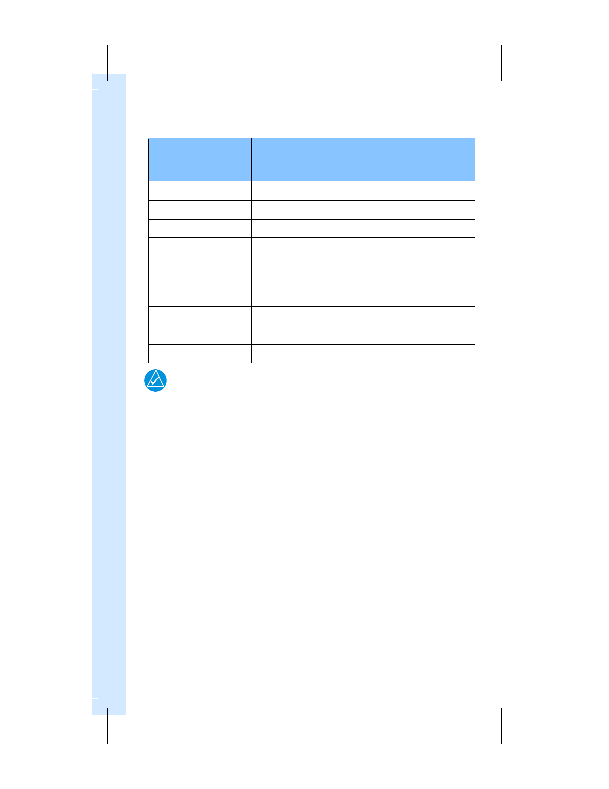
Table 5-1 FIS-B Weather Products
NOTE
Transmission
Weather Product
CONUS
NEXRAD
NEXRAD
Regional
AIRMETs
SIGMETs
METARS
Winds
and
Temperatures
Weather
Pilot
TAFs
NOTAMs (includes TFRs)
Report
Some Temporary Flight Restrictions (TFRs) may not appear, or the information
may be incomplete. TFR Information shown is only advisory in nature. To
determine accurate TFR information, verify with official sources, i.e., preflight
planning or flight service center.
Aloft
(PIREP)
Interval
(Minutes)
15 15 minutes
2.5 5 minutes
5 6 hours or as needed
5
5
10 6 hours
10 As available.
10 6 hours. As available for amended TAFs.
10 As available.
As available.
Every hour for convective SIGMETs.
15 minutes to 1 hour (METAR station dependent)
Update Interval
5 - FIS-B WEATHER AND FLIGHT INFORMATION
5-2 GTX 335/345 Pilot’s Guide 190-01499-00 Rev. E
Page 27

1 – GTX 3X5 SERIES XPDR
GTX 3X5 XPDR
6 CONNEXT BLUETOOTH
The GTX 345 Connext interface allows communication with applications
(i.e., Garmin Pilot and ForeFlight Mobile), while running on a PED. Connext works via
the Bluetooth data link to provide up-to-date, wireless information throughout the
cockpit. Refer to section 3.4 for Bluetooth pairing instructions. Up to two Bluetooth
connections are supported by the GTX 345. Table 6-1 lists the GTX 345 Connext
features.
Table 6-1 GTX 345 Connext Features
GTX 345 CONNEXT FEATURES
GPS Position and Velocity
• GPS position and velocity information used by the GTX 345's certified ADS-B
functionality is made available to PEDs.
ADS-B In Traffic
• ADS-B In traffic data that is provided to certified traffic displays is made
available to PEDs. This traffic is also combined with TCAD/TAS/TCAS traffic
when the systems are integrated during installation.
FIS-B Weather and Flight Information
• FIS-B weather and flight information that is provided to certified displays is
made available to PEDs.
Pressure Altitude
• Uncorrected barometric pressure altitude used by the GTX 345's certified
transponder and ADS-B functionality is made available to PEDs.
6 - CONNEXT BLUETOOTH
Attitude and Heading Reference System (AHRS)
• When the GTX 345 is installed as part of an integrated flight deck
(e.g., G500/G600, G1000), AHRS data from an AHRS source is made
available to PEDs.
When the GTX 345 is installed as a stand-alone device, a built-in sensor
•
provides AHRS data to PEDs via Connext. Attitude data is not output to other
installed avionics.
• The internal AHRS sensor is for use in fixed-wing aircraft only and is disabled in
helicopter installations. All internal AHRS functions are automatic and no pilot
action is required.
190-01499-00 Rev. E GTX 335/345 Pilot’s Guide 6-1
Page 28

1 – GTX 3X5 SERIES XPDR
This page intentionally left blank.
6-2 GTX 335/345 Pilot’s Guide 190-01499-00 Rev. E
Page 29
1 – GTX 3X5 SERIES XPDR
GTX 3X5 XPDR
7 TROUBLESHOOTING
The GTX 3X5 display system sends messages to the flight crew when trouble or otherwise
abnormal conditions are detected. Table 7-1 outlines troubleshooting actions the flight
crew may take to attempt to resolve each system message. If the actions taken do not
resolve the message, or if there are any questions, the Garmin Product Support
department is available Monday through Friday, 7:00 AM to 7:00 PM Central Time.
US: 913-397-8200
US Toll Free: 1-866-739-5687
Canada Toll Free: 1-866-429-9296
www.fly.garmin.com
To expedite your call, please have the following information ready.
1. System configuration (products, antennas, mounting location, etc.)
2. Model number, part number, and serial number
3. Software version(s)
4.
Description of the problem
5. Efforts made to isolate/solve the problem
7.1 Transponder Failures
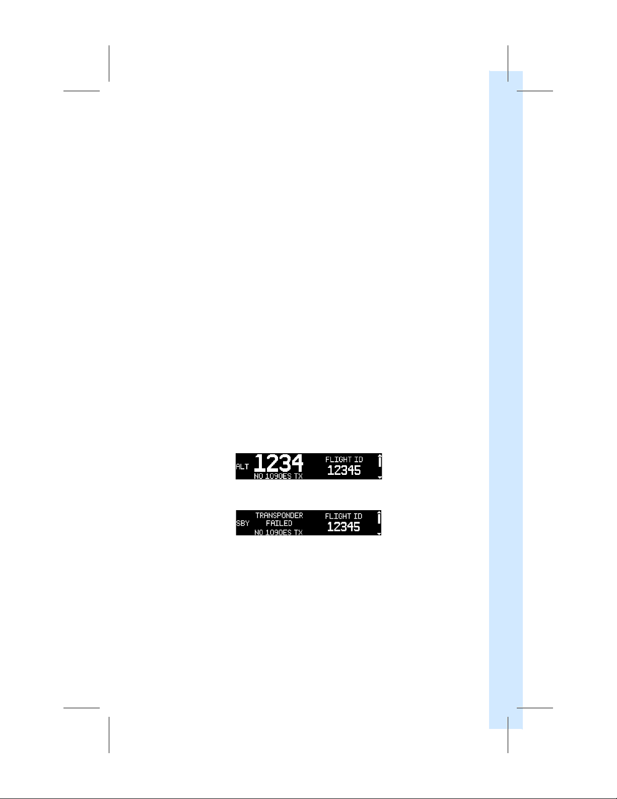
The screen in figure 7-1 shows when ADS-B is not transmitting and the aircraft may not
be compliant with 14 CFR 91.225. However, the transponder is still operating. The screen
in figure 7-2 shows if both the transponder and ADS-B are not transmitting and the
aircraft may not be compliant with 14 CFR 91. 215 and 14 CFR 91.225.
7 - TROUBLESHOOTING
Figure 7-1 ADS-B 1090ES Failed Screen
Figure 7-2 ADS-B 1090ES and Transponder Failed Screen
190-01499-00 Rev. E GTX 335/345 Pilot’s Guide 7-1
Page 30

7.2 Transponder System Messages
NOTE
Messages are not high priority. Their purpose is to provide additional
information on abnormal system behavior. They do not require immediate pilot
action. Any transponder failure will immediately display an alert with no pilot
action necessary to view the alert.
Depending on configuration, active messages display in the bottom left hand corner of
the screen either as a flashing or solid MSG. If the MSG text is configured to flash, the text
stops flashing when all active messages are read.
To view new messages:
1. Press
FUNC
key to SYS group.
2. Press
SYSTEM MESSAGE EXPLANATION FLIGHT CREW ACTION
CRSR
then
ENT
key to view message.
Table 7-1 Troubleshooting
1090 ADS-B In Failed The GTX 3X5 has detected a
1090 receiver fault. Traffic
picture may not be complete.
1090 ADS-B Out Failed The unit cannot transmit ADS-B
messages.
Note:
This message is present
regardless of whether 1090 ES is
on or off.
7 - TROUBLESHOOTING
ADS-B In Failed The GTX 3X5 has detected a
fault in both 1090 and UAT
receivers. ADS-B IN traffic
and FIS-B will not be available.
ADS-B In Traffic
Alerting Failed
The GTX 3X5 does not have
enough information to
provide traffic alerting on
ADS-B targets.
Contact dealer for service.
Contact dealer for service.
Contact dealer for service.
1. Check power and/or circuit breaker
for the GPS position source
(e.g., GTN or GNS).
2. Make sure the GPS antenna has a
clea
r view of the sky a
ugh time for the GPS position
eno
source to obtain a position fix.
Extended periods between use or
GPS position source disconnection
from the aircraft battery could
cause a longer than normal GPS
satellite acquisition time. If
problem persists, contact dealer for
service.
nd provide
7-2 GTX 335/345 Pilot’s Guide 190-01499-00 Rev. E
Page 31

1 – GTX 3X5 SERIES XPDR
GTX 3X5 XPDR
SYSTEM MESSAGE EXPLANATION FLIGHT CREW ACTION
ADS-B
Position Input Failed
Demo Mode The unit is operating in a
The unit is not receiving GPS.
mode intended for demonstration purposes.
1. Check power and/or circuit breaker
for the GPS position source
(e.g., GTN or GNS).
2. Make sure the GPS antenna has a
clear view of the sky and provide
enough time for the GPS position
source to obtain a position fix.
Extended periods betwee
GPS position source disconnection
from the aircraft battery could
cause a longer than normal GPS
satellite acquisition time.
1. Restart the unit.
2. If problem persists, cycle avionics
master power.
3. If problem persists, contact dealer
for service.
n use or
7 - TROUBLESHOOTING
FIS-B Weather Failed The FIS-B receiver has failed. The
display of FIS-B products may be
unavailable.
Ground Test The unit is operating in a
mode intended for ground
testing.
Maximum
Temperature Exceeded
Minimum
Temperature Exceeded
Pressure Altitude Failed The GTX 3X5 has lost
Service Soon GTX 3X5 has detected an
TAS/TCAS Failed TAS/TCAS is reporting failed
The unit is too hot. The
transponder will not transmit
until it has cooled.
The unit is too cold.
The transponder will not
transmit until it has warmed up.
communication with the
pressure altitude source.
internal fault but the unit will
continue to function.
or the GTX 3X5 has lost
communicating with the
TAS/TCAS.
Contact dealer for service.
Restart the unit.
Use alternate transponder as the
active transponder, if available, to
allow the GTX 3X5 to cool.
Allow time for the GTX 3X5 to warm
up to ensure proper operation.
Check power and/or circuit breaker
for the pressure altitude source
(e.g., altitude encoder, ADC, etc.).
Contact dealer for service.
Check power and/or circuit breaker
for the TCAD/TAS/TCAS I System.
190-01499-00 Rev. E GTX 335/345 Pilot’s Guide 7-3
Page 32

SYSTEM MESSAGE EXPLANATION FLIGHT CREW ACTION
Traffic Processing Failed The unit cannot process traffic
because the unit isn't receiving
enough information or the unit
has an internal fault.
1. Check power and/or circuit breaker
for the GPS position source
(e.g., GTN or GNS).
2. Make sure the GPS antenna has a
clear view of the sky and provide
enough time for the GPS position
source to obtain a position fix.
Extended periods betwee
GPS position source disconnection
from the aircraft battery could
cause a longer than normal GPS
satellite acquisition time.
3. Check Power and/or circuit breaker
for the TCAD/TAS/TCAS I system.
n use or
UAT ADS-B In Failed The GTX 3X5 has detected a
UAT receiver fault. Traffic
picture may not be complete.
7 - TROUBLESHOOTING
Contact dealer for service.
7-4 GTX 335/345 Pilot’s Guide 190-01499-00 Rev. E
Page 33

Page 34

© 2018 Garmin Ltd. or its subsidiaries
Part Number: 190-01499-00 Rev. E
 Loading...