


GTS 8XX/GPA 65
Installation Manual
(Includes the GA 58 Antenna)
190-00587-00 April, 2009 Revision 4TP
© Copyright 2009
Garmin Ltd. or its subsidiaries
All Rights Reserved
Except as expressly provided herein, no part of this manual may be reproduced, copied, transmitted,
disseminated, downloaded or stored in any storage medium, for any purpose without the express prior
written consent of Garmin. Garmin hereby grants permission to download a single copy of this manual
and of any revision to this manual onto a hard drive or other electronic storage medium to be viewed and
to print one copy of this manual or of any revision hereto, provided that such electronic or printed copy of
this manual or revision must contain the complete text of this copyright notice and provided further that
any unauthorized commercial distribution of this manual or any revision hereto is strictly prohibited.
Garmin International, Inc.
1200 E. 151
st
Street
Olathe, KS 66062 USA
Telephone: 913-397-8200
Aviation Dealer Technical Support Line (Toll Free): (888) 606-5482
www.garmin.com
Garmin (Europe) Ltd
Liberty House
Bulls Copse Road
Hounsdown Business Park
Southampton, SO40 9RB, UK
Telephone: +44 (0) 8708501241
RECORD OF REVISIONS
Revision
1TP 08/06/08 1TP Release
2TP 9/17/08 Updated manual with various engineering changes
3TP 2/18/09 Updated manual with various engineering changes
4TP Updated manual with various engineering changes
Revision
Date
Description
DOCUMENT PAGINATION
Section Page Range
Table of Contents i – vi
Section 1 1-1 – 1-10
Section 2 2-1 – 2-16
Section 3 3-1 – 3-20
Section 4 4-1 – 4-14
Appendix A A-1 – A-14
Appendix B B-1 – B-18
Page A GTS 8XX/GPA 65 Installation Manual
Revision 4TP 190-00587-00

This manual reflects the operation of software version X.XX. Some differences in operation may be
observed when comparing the information in this manual to earlier or later software versions.
INFORMATION SUBJECT TO EXPORT CONTROL LAWS
This document may contain information which is subject to the Export Administration Regulations
(“EAR”) issued by the United States Department of Commerce (15 CFR, Chapter VII Subchapter C) and
which may not be exported, released or disclosed to foreign nationals inside or outside the United States
without first obtaining an export license. The preceding statement is required to be included on any and
all reproductions in whole or in part of this manual.
NOTE
Throughout this document references made to the GTS 8XX shall equally apply to the
GTS 800, 820, and 850 except where specifically noted.
WARNING
This product, its packaging, and its components contain chemicals known to the State of
California to cause cancer, birth defects, or reproductive harm. This Notice is being
provided in accordance with California's Proposition 65. If you have any questions or
would like additional information, please refer to our web site at
www.garmin.com/prop65
.
GTS 8XX/GPA 65 Installation Manual Page i
190-00587-00 Revision 4TP

This page intentionally left blank
Page ii GTS 8XX/GPA 65 Installation Manual
Revision 4TP 190-00587-00

TABLE OF CONTENTS
PARAGRAPH PAGE
1 GENERAL DESCRIPTION..............................................................................................................1-1
1.1 Introduction........................................................................................................................................1-1
1.2 Equipment Description......................................................................................................................1-1
1.3 Interface Summary.............................................................................................................................1-1
1.4 Technical Specifications....................................................................................................................1-2
1.5 Certification.......................................................................................................................................1-4
1.6 Reference Documents........................................................................................................................1-8
1.7 Limited Warranty...............................................................................................................................1-9
2 INSTALLATION OVERVIEW........................................................................................................2-1
2.1 Introduction........................................................................................................................................2-1
2.2 Installation Considerations ................................................................................................................2-3
2.3 Electrical Bonding .............................................................................................................................2-5
2.4 Cabling and Wiring............................................................................................................................2-5
2.5 Cooling Requirements .....................................................................................................................2-15
2.6 Mounting Requirements ..................................................................................................................2-16
3 INSTALLATION PROCEDURE......................................................................................................3-1
3.1 Unpacking Unit..................................................................................................................................3-1
3.2 Wiring Harness Installation...............................................................................................................3-1
3.3 QMA Connector Insertion and Removal...........................................................................................3-3
3.4 Backshell, Pigtail Circular Connector, and Configuration Module Assemblies................................3-5
3.5 Unit Installation .................................................................................................................................3-5
3.6 GA 58 Antenna Installation.............................................................................................................3-19
3.7 GPA 65 PA/LNA Installation..........................................................................................................3-20
3.8 Continued Airworthiness.................................................................................................................3-20
4 SYSTEM INTERCONNECTS..........................................................................................................4-1
4.1 GTS 8XX Pin Function List ..............................................................................................................4-1
4.2 GPA 65 Pin Function List..................................................................................................................4-6
4.3 Power.................................................................................................................................................4-7
4.4 Serial Data .........................................................................................................................................4-9
4.5 Configuration...................................................................................................................................4-12
4.6 Analog/Discrete...............................................................................................................................4-12
4.7 Mutual Suppression Bus..................................................................................................................4-14
APPENDIX A: OUTLINE & INSTALLATION DRAWINGS..............................................................A-1
APPENDIX B: INTERCONNECT EXAMPLE...................................................................................... B-1
GTS 8XX/GPA 65 Installation Manual Page iii
190-00587-00 Revision 4TP

LIST OF ILLUSTRATIONS
FIGURE PAGE
2-1 GTS 800 Installation with Top and Bottom Directional Antennas....................................................2-7
2-2 GTS 800 Installation with Top and Bottom Monopole Antennas.....................................................2-8
2-3 GTS 800 Installation with Top Directional Antennas and no Bottom Antenna................................2-8
2-4 GTS 820/GTS 850 Installation Top and Bottom Directional Antennas............................................2-9
2-5 GTS 820/GTS 850 Installation with Top Directional and Bottom Monopole Antenna..................2-10
2-6 GTS 820/GTS 850 Installation with Top Directional and no Bottom Antenna...............................2-10
2-7 RG-400/RG-142 Coaxial Cable Stripping Dimensions...................................................................2-14
2-8 Ferrule and Crimp Die Positioning..................................................................................................2-14
2-9 Heat Shrink Positioning...................................................................................................................2-15
2-10 GTS 8XX Vertical Installation Rack (Garmin P/N 115-00781-00) ................................................2-16
2-11 GTS 8XX Horizontal Installation Rack (Garmin P/N 115-00784-00)............................................2-16
3-1 Engaging QMA Connectors...............................................................................................................3-3
3-2 Disengaging QMA Connectors..........................................................................................................3-4
3-3 GTS 8XX Install Tool – Normal Tab................................................................................................3-7
3-4 GTS 8XX Install Tool – Configuration Tab (GTS 800)....................................................................3-8
3-5 GTS 8XX Install Tool – Configuration Tab (GTS 820 and GTS 850)..............................................3-9
3-6 GTS 8XX Install Tool – Upload Tab...............................................................................................3-12
3-7 Self Test...........................................................................................................................................3-15
3-8 Ground Test .....................................................................................................................................3-16
A-1 GTS 8XX Vertical Outline Drawing ................................................................................................A-1
A-2 GTS 8XX Vertical Installation Drawing ..........................................................................................A-3
A-3 GTS 8XX Horizontal Outline Drawing............................................................................................A-5
A-4 GTS 8XX Horizontal Installation Drawing......................................................................................A-7
A-5 GPA 65 Outline Drawing .................................................................................................................A-9
A-6 GPA 65 Installation Drawing .........................................................................................................A-11
A-7 GA 58 Antenna Outline Drawing...................................................................................................A-13
B-1 Notes................................................................................................................................................. B-1
B-2 GTS 820/850/GPA 65 Example Interconnect ................................................................................... B-3
B-3 GTS 800 Example Interconnect........................................................................................................ B-5
B-4 GTS 8XX G1000 Example Interconnect ..........................................................................................B-7
B-5 GTS 8XX GNS 4XX/GNS 5XX/GMX 200 Example Interconnect.................................................B-9
B-6 GTS 8XX/GMA/Altimeter Example Interconnect ......................................................................... B-11
B-7 GTS 8XX Dongle Cable (Non-G 1000 Installations Only).............................................................B-13
B-8 GTS 8XX Discrete Interconnects ................................................................................................... B-15
B-9 GTS 8XX Config Module Example Interconnect .......................................................................... B-17
Page iv GTS 8XX/GPA 65 Installation Manual
Revision 4TP 190-00587-00

LIST OF TABLES
TABLE PAGE
2-1 GPA 65 Minimum Wiring Requirements..........................................................................................2-6
2-2 Cable Types and QMA Connectors.................................................................................................2-11
2-3 Recommended Coaxial Length........................................................................................................2-12
2-4 Coaxial Cable Set Length Tolerance ...............................................................................................2-13
3-1 Socket and Pin Contact part Numbers...............................................................................................3-1
3-2 Socket Contact MIL SPEC M39029/5-115 Crimp Tooling...............................................................3-1
3-3 Pin Contact GPN 336-00021-00 MIL SPEC M39029/58-360 Crimp Tooling .................................3-2
3-4 Pin Socket Contacts GPN 336-00022-00 MIL SPEC M39029/63-368 and GPN 336-00023-00 Crimp
Tooling...............................................................................................................................................3-2
3-5 Self Test...........................................................................................................................................3-15
GTS 8XX/GPA 65 Installation Manual Page v
190-00587-00 Revision 4TP

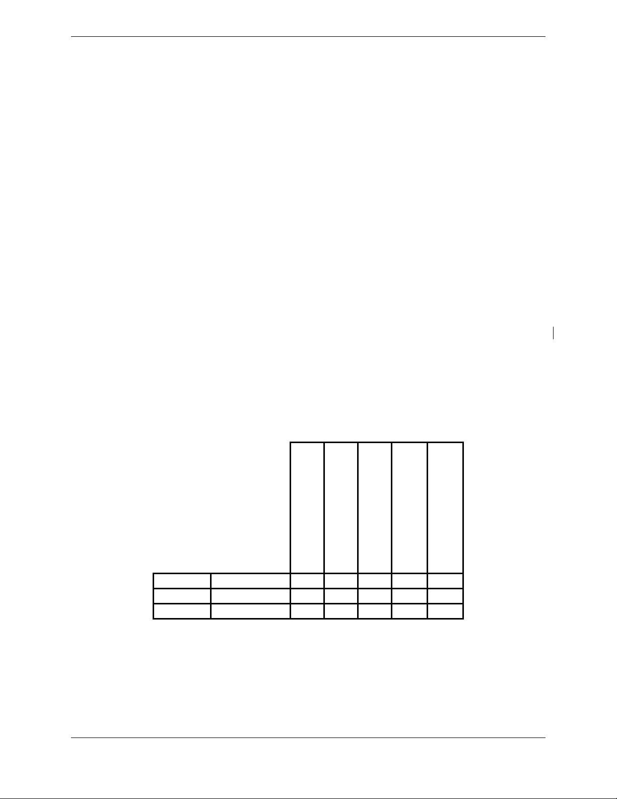
GTS 8XX HARDWARE MOD LEVEL HISTORY
The following table identifies hardware modification (Mod) Levels for the GTS 8XX. Mod Levels are
listed with the associated service bulletin number, service bulletin date, and the purpose of the
modification. The table is current at the time of publication of this manual (see date on front cover) and is
subject to change without notice. Authorized Garmin Sales and Service Centers are encouraged to access
the most up-to-date bulletin and advisory information on the Garmin Dealer Resource web site at
www.garmin.com
APPLICABLE
LRU PART
NUMBER
using their Garmin-provided user name and password.
MOD
LEVEL
SERVICE
BULLETIN
NUMBER
SERVICE
BULLETIN
DATE
PURPOSE OF
MODIFICATION
Page vi GTS 8XX/GPA 65 Installation Manual
Revision 4TP 190-00587-00
(
)
1 GENERAL DESCRIPTION
1.1 Introduction
This manual presents mechanical and electrical installation requirements for installing the
GTS 8XX/GPA 65 Traffic Advisory System (TAS) and Traffic Collision Avoidance System (TCAS I).
1.2 Equipment Description
The GTS 8XX is a microprocessor-based Line Replaceable Unit (LRU) that uses active interrogations of
Mode S (GTS 820 and GTS 850 only) and Mode C transponders to provide Traffic Advisories to the
pilot. The GTS 820 and GTS 850 include a GPA 65 power amplifier/low-noise amplifier (PA/LNA)
module, which allows for up to 40 nm of active surveillance range as well as Mode S interrogation
capability. When installed with a 1090 MHz ADS-B transmit class of equipment the GTS 8XX also
utilizes passive surveillance. Traffic is displayed on an external MFD via ARINC 429 and/or Ethernet
High Speed Data Bus (HSDB). An aural alert is also provided to inform the crew a traffic advisory (TA)
will be displayed.
A top-mounted directional antenna is used to derive bearing of the intruder aircraft, which is displayed
with relative altitude to own aircraft. Top antenna transmitted interrogations are directional, reducing the
number of transponders that receive the interrogation thus reducing potential garble on the 1090 MHz
band. Optional bottom antenna transmit interrogations are omni directional, using a monopole antenna
(recommended for fixed gear installations) or a directional antenna (recommended for retractable gear
installations). A bottom directional antenna installation gives the benefit of intruder bearing visibility for
targets that are shaded from the top directional antenna.
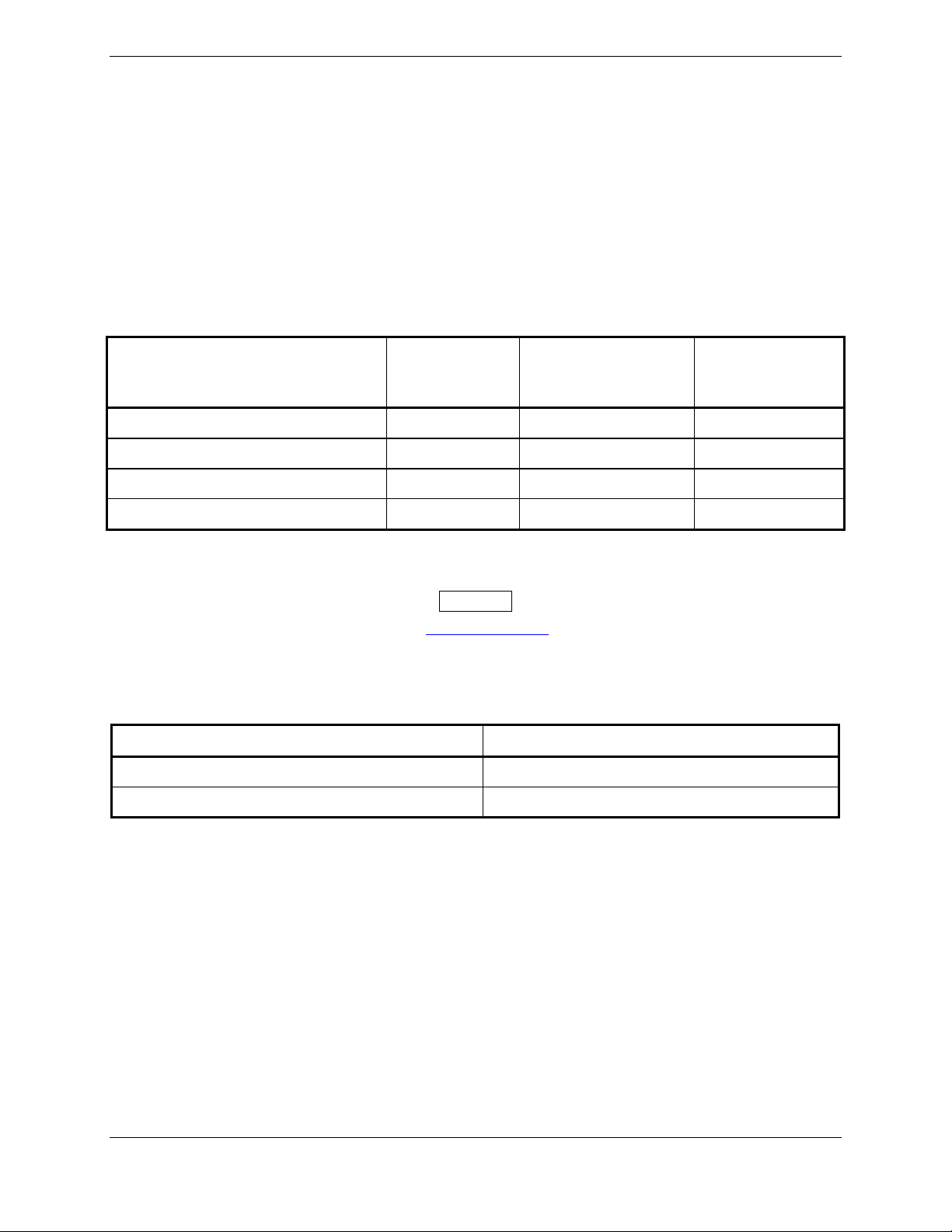
1.2.1 GTS 8XX Model Differences
The following table summarizes the differences between the various GTS 8XX models documented in
this manual.
GTS 800 011-01356-00
GTS 820 011-01446-00
GTS 850 011-01553-00
(TAS)
Traffic Advisory System
X X 40
X X X 200
X X X 200
TCAS I
Receiver
Traffic Collision
1090 ES ADS-B
Avoidance System
GPA 65
PA/LNA
(Watts)
Transmit Power
1.3 Interface Summary
The GTS 8XX is designed as an open architecture system that uses typical ARINC 429, RS-232, and
Ethernet communications interfaces.
GTS 8XX/GPA 65 Installation Manual Page 1-1
190-00587-00 Revision 4TP

1.4 Technical Specifications
1.4.1 Environmental Qualification Form
It is the responsibility of the installing agency to obtain the latest revision of the GTS 8XX/GPA
Environmental Qualification Form. This form is available directly from Garmin under the following part
number:
GTS 8XX Environmental Qualification Form, Garmin part number 005-00323-02
GPA 65 PA/LNA Environmental Qualification Form, Garmin part number 005-00323-22
GA 58 Antenna Environmental Qualification Form, Garmin part number 005-00232-23
To obtain a copy of this form, see the dealer/OEM portion of the Garmin web site (www.garmin.com
).
1.4.2 Physical Characteristics
Characteristics Specifications
GTS 8XX Width 2.81 inches (7.14 cm)
GTS 8XX Height 6.94 inches (17.63 cm)
GTS 8XX Depth w/Connector Kit 14.78 inches (37.54 cm)
GPA 65 Width 4.25 inches (10.80 cm)
GPA 65 Height 1.00 inches (2.54 cm)
GPA 65 Depth Not Including
Connector And Cable
GPA 65 Depth w/Connector And
Cable Fully Extended
GTS 8XX Unit Weight w/out
Connector Kit
GTS 8XX Unit Weight with
Connector Kit/w Vertical Rack
GTS 8XX Unit Weight with
Connector Kit/w Horizontal Rack
GPA 65 PA/LNA Unit Weight with
Pigtail Connector Kit*
GA 58 TAS/TCAS Antenna
w/screws and o-ring
QMA straight connector kit, 4 pcs 0.10 lbs. (0.05 kg)
QMA straight connector kit, 1 pc 0.03 lbs. (0.01 kg)
QMA right angle connector kit,
4 pcs
QMA right angle connector kit, 1 pc 0.05 lbs. (0.02 kg)
QMA termination connector kit 0.07 lbs. (0.03 kg)
*Used with the GTS 820 and 850.
7.96 inches (20.22 cm)
16.83 inches (42.75 cm)
9.0 lbs. (4.08 kg)
10.7 lbs. (4.85 kg)
11.5 lbs. (5.22 kg)
1.9 lbs. (0.86 kg)
0.82 lbs. (0.37 kg)
0.18 lbs. (0.08 kg)
Page 1-2 GTS 8XX/GPA 65 Installation Manual
Revision 4TP 190-00587-00

1.4.3 General Specifications
The table below contains general specifications. For detailed environmental specifications, see the
Environmental Qualification Form.
Characteristics Specifications
Operating Temperature Range -55°C to +70°C.
Humidity 95% non-condensing
Altitude Range -1,500 ft to 55,000 ft
Software Compliance RTCA/DO-178B levels B, C, and D
Hardware Compliance RTCA/DO-254 Level C
Environmental Compliance RTCA/DO-160E
1.4.4 Power Requirements
Characteristics Specifications
GTS 8XX Power Requirements 14/28 Vdc. See the Environmental Qualification Form for
details on surge ratings and minimum/maximum operating
voltages.
GTS 800 Power Consumption 1.1 +/- 0.2 A typical 1.5 A max operating @ 28 Vdc
2.2 +/- 0.2 A typical 2.6 A max operating @ 14 Vdc
GTS 820/850 Power Consumption 1.3 +/- 0.2 A typical 1.6 A max operating @ 28 Vdc
2.7 +/- 0.3 A typical 3.2 A max operating @ 14 Vdc
GTS 8XX Boot-up Current Draw 4.0 A @ 28 Vdc for 70 ms
5.6 A @ 14 Vdc for 100 ms
GTS 8XX/GPA 65 Installation Manual Page 1-3
190-00587-00 Revision 4TP

1.5 Certification
The conditions and tests required for TSO approval of this article are minimum performance standards. It
is the responsibility of those installing this article either on or within a specific type or class of aircraft to
determine that the aircraft installation conditions are within the TSO standards. TSO articles must have
separate approval for installation in an aircraft. The article may be installed only if performed under 14
CFR part 43 or the applicable airworthiness requirements.
The following table provides a list of applicable TSO/ETSOs for the GTS 8XX/GPA 65.
1.5.1 TSO/ETSO Compliance
Applicable
LRU
GTS 850
GPA 65
GTS 800
GTS 820
GPA 65
GTS 800
GTS 820
GTS 850
Function TSO/ETSO Category
Traffic Alert and Collision
Avoidance System (TCAS I)
Airborne Equipment
Traffic Advisory System
(TAS) Airborne Equipment
Extended Squitter Automatic
Dependent Surveillance –
Broadcast (ADS-B) and
Traffic Information Service –
Broadcast (TIS-B)
Equipment Operating on the
Radio Frequency of 1090
Megahertz (MHz)
TSO-C118
ETSO-C118
TSO-C147
ETSO-C147
TSO-C166a
Applicable
LRU SW Part
Numbers
006-B0551-()
Class A 006-B0551-()
Class
A0/Type 1
Receiving
Only*
Class
A1/Type 1
Receiving
Only*
006-B0551-() 006-C0081-()**
Applicable
CLD Part
Numbers
006-C0081-()**
006-C0092-()***
006-C0081-()**
006-C0092-()***
* Equipment is Class A0 when installed with a single antenna, Class A1 when installed with diversity
antennas.
**GTS 8XX only
***GPA 65 only
Page 1-4 GTS 8XX/GPA 65 Installation Manual
Revision 4TP 190-00587-00

1.5.2 TSO/ETSO Deviations
1.5.2.1 GTS 800
TSO/ETSO Deviation
TSO-C147 1. Garmin was granted a deviation from TSO-C147 section 1.c to use RTCA DO-160E, instead of
RTCA DO-160D as the standard for Environmental Conditions and Test Procedures for Airborne
Equipment.
RTCA DO-197A
RTCA DO-185A
RTCA DO-260A
1. Garmin was granted a deviation from RTCA DO-197A section 2.2.3.2.1 to use the Interrogations
Spectrum requirement of RTCA DO-185A section 2.2.3.3 instead of the requirement of RTCA DO197A section 2.2.3.2.1
3. Garmin was granted a deviation from RTCA DO-197A section 2.2.9.1 to realize the bearing
estimation function using a direction finding antenna augmented by tracked correlated ADS-B data
when such data is available and of sufficient integrity.
4. Garmin was granted a deviation from RTCA DO-197A section 2.2.11 to use the suppression
pulse on the aircraft suppression bus specified by RTCA DO-185A section 2.2.3.12 (70 +/-1 µs from
top antenna and 90 +/-1 µs from bottom antenna) instead of 100 +/-5 µs.
1. Garmin was granted a deviation to use DO-185A as modified by Appendix 1 of TSO-C119B and
‘RWG Recommended Modification 2.0 to TSO-C119B.’
2. Garmin was granted a deviation from RTCA DO-185A section 2.2.3.8.2 Mode S signal definition.
3. Garmin was granted a deviation from RTCA DO-185A section 2.2.4.4.2.2.b to use the Enhanced
Preamble Detection method of RTCA DO-260A Appendix I section I.4.1.
4. Garmin was granted a deviation from RTCA DO-185A section 2.2.4.4.2.2.c to use the Baseline
Multi-sample bit and confidence declaration technique of RTCA DO-260A Appendix I section
I.4.2.3.1.
5. Garmin was granted a deviation from RTCA DO-185A section 2.4.2.1.1.4.
1. Garmin was granted a deviation from RTCA DO-260A section 2.2.4.3.4.7.3.b to use the
Conservative and Brute Force error correction techniques specified by RTCA DO-260A section
2.2.4.4.3.1 instead of section 2.2.4.4.2.2.d and Appendix A, Section 3 of RTCA DO-185A.
2. Garmin was granted a deviation from RTCA DO-260A section 2.2.4.4.2 to use the Conservative
and Brute Force error correction techniques specified by RTCA DO-260A section 2.2.4.4.3.1
instead of section 2.2.4.4.2.2.d and Appendix A, Section 3 of RTCA DO-185A.
3. Garmin was granted a deviation from RTCA DO-260A section 2.2.4.5.b to use the Conservative
and Brute Force error correction techniques specified by RTCA DO-260A section 2.2.4.4.3.1
instead of section 2.2.4.4.2.2.d and Appendix A, Section 3 of RTCA DO-185A.
GTS 8XX/GPA 65 Installation Manual Page 1-5
190-00587-00 Revision 4TP

1.5.2.2 GTS 820
TSO/ETSO Deviation
TSO-C147
RTCA DO-197A
RTCA DO-185A
RTCA DO-260A
1. Garmin was granted a deviation from TSO-C147 section 1.c to use RTCA DO-160E, instead of
RTCA DO-160D as the standard for Environmental Conditions and Test Procedures for Airborne
Equipment.
2. Garmin was granted a deviation from TSO-C147 Appendix 1 section 1.6 to use selective Mode S
interrogations as specified by RTCA DO-185A section 2.2.3.8.1 and 2.2.3.9 following all the
applicable protocols for Mode-S surveillance interrogations in the NAS as stated in DO-1 85A and
DO-181C.
1. Garmin was granted a deviation from RTCA DO-197A section 2.2.3.2.1 to use the Interrogations
Spectrum requirement of RTCA DO-185A section 2.2.3.3 instead of the requirement of RTCA DO197A section 2.2.3.2.1
2. Garmin was granted a deviation from RTCA DO-197A section 2.2.3.5 to use the “Mode C Only
All-Call” format specified by RTCA DO-185A section 2.2.3.8.1 instead of the “Mode C” format for
ATCRBS interrogations.
3. Garmin was granted a deviation from RTCA DO-197A section 2.2.9.1 to realize the bearing
estimation function using a direction finding antenna augmented by tracked correlated ADS-B data
when such data is available and of sufficient integrity.
4. Garmin was granted a deviation from RTCA DO-197A section 2.2.11 to use the suppression
pulse on the aircraft suppression bus specified by RTCA DO-185A section 2.2.3.12 (70 +/-1 µs from
top antenna and 90 +/-1 µs from bottom antenna) instead of 100 +/-5 µs.
1. Garmin was granted a deviation to use DO-185A as modified by Appendix 1 of TSO-C119B and
‘RWG Recommended Modification 2.0 to TSO-C119B.’
2. Garmin was granted a deviation from RTCA DO-185A section 2.2.3.8.2 Mode S signal definition.
3. Garmin was granted a deviation from RTCA DO-185A section 2.2.4.4.2.2.b to use the Enhanced
Preamble Detection method of RTCA DO-260A Appendix I section I.4.1.
4. Garmin was granted a deviation from RTCA DO-185A section 2.2.4.4.2.2.c to use the Baseline
Multi-sample bit and confidence declaration technique of RTCA DO-260A Appendix I section
I.4.2.3.1.
5. Garmin was granted a deviation from RTCA DO-185A section 2.4.2.1.1.4.
1. Garmin was granted a deviation from RTCA DO-260A section 2.2.4.3.4.7.3.b to use the
Conservative and Brute Force error correction techniques specified by RTCA DO-260A section
2.2.4.4.3.1 instead of section 2.2.4.4.2.2.d and Appendix A, Section 3 of RTCA DO-185A.
2. Garmin was granted a deviation from RTCA DO-260A section 2.2.4.4.2 to use the Conservative
and Brute Force error correction techniques specified by RTCA DO-260A section 2.2.4.4.3.1
instead of section 2.2.4.4.2.2.d and Appendix A, Section 3 of RTCA DO-185A.
3. Garmin was granted a deviation from RTCA DO-260A section 2.2.4.5.b to use the Conservative
and Brute Force error correction techniques specified by RTCA DO-260A section 2.2.4.4.3.1
instead of section 2.2.4.4.2.2.d and Appendix A, Section 3 of RTCA DO-185A.
Page 1-6 GTS 8XX/GPA 65 Installation Manual
Revision 4TP 190-00587-00

1.5.2.3 GTS 850
TSO/ETSO Deviation
TSO-C118
RTCA DO-197A
RTCA DO-185A
RTCA DO-260A
1. Garmin was granted a deviation from TSO-C118 section a.(2) to use RTCA DO-160E, instead of
RTCA DO-160B as the standard for Environmental Conditions and Test Procedures for Airborne
Equipment.
1. Garmin was granted a deviation from RTCA DO-197A section 2.2.3.2.1 to use the Interrogations
Spectrum requirement of RTCA DO-185A section 2.2.3.3 instead of the requirement of RTCA DO197A section 2.2.3.2.1.
2. Garmin was granted a deviation from RTCA DO-197A section 2.2.3.5 to use the “Mode C Only
All-Call” format specified by RTCA DO-185A section 2.2.3.8.1 instead of the “Mode C” format for
ATCRBS interrogations.
3. Garmin was granted a deviation from RTCA DO-197A section 2.2.6 to use selective Mode S
interrogations following all the applicable protocols for Mode-S surveillance interrogations in the
NAS as stated in DO-185A and DO-181C.
4. Garmin was granted a deviation from RTCA DO-197A section 2.2.9.1 to realize the bearing
estimation function using a direction finding antenna augmented by tracked correlated ADS-B data
when such data is available and of sufficient integrity.
5. Garmin was granted a deviation from RTCA DO-197A section 2.2.11 to use the suppression
pulse on the aircraft suppression bus specified by RTCA DO-185A section 2.2.3.12 (70 +/-1 µs from
top antenna and 90 +/-1 µs from bottom antenna) instead of 100 +/-5 µs.
1. Garmin was granted a deviation to use RTCA DO-185A as modified by Appendix 1 of TSOC119B and ‘RWG Recommended Modification 2.0 to TSO-C119B’.
2. Garmin was granted a deviation from RTCA DO-185A section 2.2.3.8.2 Mode S signal definition.
3. Garmin was granted a deviation from RTCA DO-185A section 2.2.4.4.2.2.b to use the Enhanced
Preamble Detection method of RTCA DO-260A Appendix I section I.4.1.
4. Garmin was granted a deviation from RTCA DO-185A section 2.2.4.4.2.2.c to use the Baseline
Multi-sample bit and confidence declaration technique of RTCA DO-260A Appendix I section
I.4.2.3.1.
1. Garmin was granted a deviation from RTCA DO-260A section 2.2.4.3.4.7.3.b to use the
Conservative and Brute Force error correction techniques specified by RTCA DO-260A section
2.2.4.4.3.1 instead of section 2.2.4.4.2.2.d and Appendix A, Section 3 of RTCA DO-185A.
2. Garmin was granted a deviation from RTCA DO-260A section 2.2.4.4.2 to use the Conservative
and Brute Force error correction techniques specified by RTCA DO-260A section 2.2.4.4.3.1
instead of section 2.2.4.4.2.2.d and Appendix A, Section 3 of RTCA DO-185A.
3. Garmin was granted a deviation from RTCA DO-260A section 2.2.4.5.b to use the Conservative
and Brute Force error correction techniques specified by RTCA DO-260A section 2.2.4.4.3.1
instead of section 2.2.4.4.2.2.d and Appendix A, Section 3 of RTCA DO-185A.
GTS 8XX/GPA 65 Installation Manual Page 1-7
190-00587-00 Revision 4TP

1.6 Reference Documents
The following publications are sources of additional information for installing the GTS 8XX. Before
installing the GTS 8XX, the technician should read all referenced materials along with the manual.
Part Number Document
190-00313-11 Jackscrew Backshell Installation Instructions
190-00303-00 G1000 System Installation Manual
190-00303-04
190-00903-00 G1000 System Maintenace Manual LJ/VLJ
190-00907-00
G1000 Line Maintenance and Configuration
Manual
G1000 System Maintenance Manual Standard
Piston/Turboprop Aircraft
Page 1-8 GTS 8XX/GPA 65 Installation Manual
Revision 4TP 190-00587-00

1.7 Limited Warranty
This Garmin product is warranted to be free from defects in materials or workmanship for two years from
the date of purchase. Within this period, Garmin will at its sole option, repair or replace any components
that fail in normal use. Such repairs or replacement will be made at no charge to the customer for parts or
labor, provided that the customer shall be responsible for any transportation cost. This warranty does not
cover failures due to abuse, misuse, accident or unauthorized alteration or repairs.
THE WARRANTIES AND REMEDIES CONTAINED HEREIN ARE EXCLUSIVE AND IN LIEU OF
ALL OTHER WARRANTIES EXPRESS OR IMPLIED OR STATUTORY, INCLUDING ANY
LIABILITY ARISING UNDER ANY WARRANTY OF MERCHANTABILITY OR FITNESS FOR A
PARTICULAR PURPOSE, STATUTORY OR OTHERWISE. THIS WARRANTY GIVES YOU
SPECIFIC LEGAL RIGHTS, WHICH MAY VARY FROM STATE TO STATE.
IN NO EVENT SHALL GARMIN BE LIABLE FOR ANY INCIDENTAL, SPECIAL, INDIRECT OR
CONSEQUENTIAL DAMAGES, WHETHER RESULTING FROM THE USE, MISUSE, OR
INABILITY TO USE THIS PRODUCT OR FROM DEFECTS IN THE PRODUCT. Some states do not
allow the exclusion of incidental or consequential damages, so the above limitations may not apply to
you.
Garmin retains the exclusive right to repair or replace the unit or software or offer a full refund of the
purchase price at its sole discretion. SUCH REMEDY SHALL BE YOUR SOLE AND EXCLUSIVE
REMEDY FOR ANY BREACH OF WARRANTY.
To obtain warranty service, contact your local Garmin Authorized Service Center. For assistance in
locating a Service Center near you, call Garmin Customer Service at one of the numbers shown below.
Products sold through online auctions are not eligible for rebates or other special offers from Garmin.
Online auction confirmations are not accepted for warranty verification. To obtain warranty service, an
original or copy of the sales receipt from the original retailer is required. Garmin will not replace missing
components from any package purchased through an online auction.
Garmin International, Inc. Garmin (Europe) Ltd.
1200 E. 151st Street Liberty House
Olathe, KS 66062, U.S.A. Bulls Copse Road
Phone: 800/800.1020 Hounsdown Business Park
FAX: 913/397.0836 Southampton, SO40 9RB, UK
Telephone: 44 (0) 8708501241
GTS 8XX/GPA 65 Installation Manual Page 1-9
190-00587-00 Revision 4TP

This page intentionally left blank
Page 1-10 GTS 8XX/GPA 65 Installation Manual
Revision 4TP 190-00587-00
2 INSTALLATION OVERVIEW
2.1 Introduction
This section provides hardware equipment information for installing the GTS 8XX/GPA 65 and related
hardware. Installation of the GTS 8XX/GPA 65 should follow the aircraft TC or STC requirements.
Cabling is fabricated by the installing agency to fit each particular aircraft. The guidance of FAA
advisory circulars AC 43.13-1B and AC 43.13-2A, where applicable, may be found useful for making
retro-fit installations that comply with FAA regulations.
2.1.1 Unit Configurations
The GTS 8XX and GPA 65 are available under the following part numbers:
Applicable
Item
GTS 800, (011-01356-00) 006-B0551-() 006-C0081-() 010-00519-00
GTS 820, (011-01446-00) 006-B0551-() 006-C0081-() 010-00562-00
GTS 850, (011-01553-00) 006-B0551-() 006-C0081-() 010-00563-00
GPA 65, (011-01347-00) 006-B0551-() 006-C0092-() 010-10721-00
LRU Software
Part Numbers
Applicable Custom
Logic Device
Part Numbers
Garmin P/N
2.1.2 Required Accessories
NOTE
Refer to the Dealer’s Only portion of www.garmin.com for instructions on determining
what accessories are needed.
Each of the following accessories are provided separately from the GTS 8XX and GPA 65 unit and are
required to install the unit.
Installation Racks* Garmin P/N
GTS 8XX Vertical Installation Rack 115-00781-00
GTS 8XX Horizontal Installation Rack 115-00784-00
* Only one is required.
GTS 8XX/GPA 65 Installation Manual Page 2-1
190-00587-00 Revision 4TP

For a GTS 800 installation with a single GA 58 directional antenna, two QMA Connector Kits (4 pieces,
either straight or right angle) are required.
For a GTS 800 installation with dual GA 58 directional antennas, four QMA Connector Kits (4 pieces,
either straight or right angle) kits are required.
For a GTS 800 installation with a single GA 58 directional antenna and a monopole antenna, two QMA
Connector Kits (4 pieces, either straight or right angle) and one QMA Connector Kit (1 piece, either
straight or right angle) are required.
For GTS 820 and 850 installations, add two QMA Connector Kits (4 pieces, either straight or right angle)
for the GPA 65 connections.
One QMA Termination Connector Kit (4 pieces) is required for single antenna installations.
Connector Kits Garmin P/N
QMA Right Angle Connector Kit (4 pieces) 011-01364-00
QMA Straight Connector Kit (4 pieces) 011-01364-01
QMA Right Angle Connector Kit (1 piece) 011-01364-02
QMA Straight Connector Kit (1 piece) 011-01364-03
QMA Termination Connector Kit (4 pieces) 011-01364-04
GTS 8XX Connector Kit 011-01360-00
GPA 65 Circular Connector Kit 011-01365-00
USB-B Pigtail (non-G1000 installations only) 011-01782-00
Antennas Garmin P/N
GA 58 Directional Antenna, (011-01346-00) 010-10720-00*
Monopole Antenna 010-10160-00 or
L-Band Monopole Antenna that meets
TSO-C74c
*010-10720-00 includes mounting screws and o-ring, unless specifically requested to exclude.
Configuration Module Garmin P/N
Configuration Module (non-G1000 installations
only)
011-00979-20
Page 2-2 GTS 8XX/GPA 65 Installation Manual
Revision 4TP 190-00587-00

2.2 Installation Considerations
Fabrication of a wiring harness is required. Sound mechanical and electrical methods and practices are
required for installation of the GTS 8XX/GPS 65.
2.2.1 Antenna Considerations
Antenna installations on pressurized cabin aircraft require FAA approved installation design and
engineering substantiation data whenever such antenna installations incorporate alteration (penetration) of
the cabin pressure vessel by connector holes and/or mounting arrangements. For needed engineering
support pertaining to the design and approval of such pressurized aircraft antenna installations, it is
recommended that the installer proceed according to any of the following listed alternatives:
1. Obtain approved antenna installation design data from the aircraft manufacturer.
2. Obtain an FAA approved STC, pertaining to, and valid for the antenna installation.
3. Contact the FAA Aircraft Certification Office in the appropriate Region and request identification
of FAA Designated Engineering Representatives (DERs) who are authorized to prepare and
approve the required antenna installation engineering data.
4. Obtain FAA Advisory Circular AC-183C and identify a DER from the roster of individuals in it.
5. Contact an aviation industry organization such as the Aircraft Electronics Association for
assistance.
For all composite aircraft, antenna installation requires that a ground plane be fabricated on the internal
surface of the aircraft directly under the antenna. The TAS/TCAS antenna pattern is dependent upon a
ground plane under the antenna. The minimum recommended antenna ground plane dimensions are
18” x 18” for composite aircraft.
A fabricated doubler plate assembly supplied by the installing agent or antenna vendor may be required
inside the fuselage to complete the antenna hardware installation.
NOTE
For all GTS 8XX installations, a monopole antenna is recommended if installing an
optional bottom mounted antenna on a fixed-gear aircraft, while retractable-gear aircraft
may use either a monopole or a directional bottom mounted antenna. The target bearing
accuracy may be degraded for bottom directional antenna installations on aircraft with
fixed gear.
GTS 8XX/GPA 65 Installation Manual Page 2-3
190-00587-00 Revision 4TP

2.2.1.1 TAS/TCAS Antenna Location
To achieve proper interrogation and surveillance volumes the following GTS 8XX antenna installation
guidelines should be followed.
The GTS 8XX requires a top-mounted directional antenna. An optional bottom mounted directional or
L-band monopole antenna can be installed in conjunction with the top-mounted directional antenna.
Antenna locations are critical to maintain the surveillance coverage across all azimuth and elevation
angles. Locations shall be chosen so the top mounted and bottom mounted antenna will represent same
range and bearing to an intruder. The mounting location, geometry, and surroundings of the antenna can
affect the system performance. The following guidance provides information to aid the installer in
ensuring that the most optimum location is selected for the installation of the antenna. Because meeting
all of these installations guidelines may not be possible on all aircraft, these guidelines are listed in order
of importance to achieve optimum performance. The installer must use best judgment to balance the
installation guidelines.
Installations must be thoroughly tested to verify that performance degradation as a result of antenna
placement is not an issue for the TAS/TCAS system as well as other systems.
1. As far as physically possible, the top directional antenna shall be mounted at the most forward
location.
2. The TAS/TCAS antenna(s) shall be mounted on the aircraft skin so that the horizontal base is
horizontal to within +/-5° in longitudinal and lateral axes when the aircraft is in level flight.
3. The TAS/TCAS antenna(s) shall be mounted on a flat section of the fuselage to reduce the gap
formed between the base plate and the fuselage when normal mounting torque is applied.
4. It is recommended that all antennas be mounted at least 20 inches away (measured from center to
center) from the TAS/TCAS antenna(s).
5. Ground plane considerations shall include minimization of any discontinuities such as overlapped
un-riveted airframe skins, cowlings, or hatches. It is recommended that all such discontinuities be
at least 18 inches from the nearest edge of the TAS/TCAS antenna.
6. For installations using a bottom mounted antenna, it is recommended that the top and bottom
antennas be located near the same vertical line through the aircraft such that they represent the
same range and bearing to an intruder.
7. The top and bottom mounted TAS/TCAS Antenna shall be as close as possible to the aircraft
centerline.
8. It is recommended that no antenna be mounted in front of the TAS/TCAS antenna(s).
Page 2-4 GTS 8XX/GPA 65 Installation Manual
Revision 4TP 190-00587-00

2.3 Electrical Bonding
Electrical equipment, supporting brackets, and racks should be electrically bonded to the aircraft’s main
structure. Refer to SAE ARP 1870 section 5 when surface preparation is required to achieve electrical
bond. The electrical bond should achieve direct current (DC) resistance less than or equal to 2.5
milliohms to local structure to where the equipment is mounted. Compliance should be verified by
inspection using a calibrated milliohm meter. An equivalent OEM procedure may also be substituted.
There may be OEM-specific reasons for electrically isolating equipment or having a higher bond
resistance. These reasons should be rationalized upon installation approval. In general, Garmin
recommends that all GTS 8XX equipment be electrically bonded.
The antenna ground plane and doubler plate must be electrically bonded to the antenna baseplate. The
electrical bond must achieve direct current (DC) resistance less than or equal to 2.5 milliohms.
For composite aircraft, the antenna baseplate must be electrically bonded to the common ground of other
installed equipment for lightning purposes. This can be achieved through the antenna mounting screws.
2.4 Cabling and Wiring
Use #24 AWG or larger diameter wire for all connections unless otherwise specified. The minimum
diameter wire size for all GTS 8XX installation wiring is #24 AWG, except in the case of Aircraft Power
and Aircraft Ground and both shall be a minimum of #18 AWG. Refer to Table 2-1 for GPA 65 wiring
specifications.
A single circuit breaker shall be dedicated to the GTS 8XX unless specifically approved by the
manufacturer on a case by case basis, or allowed by the STC. Do not attempt to combine more than one
unit on the same circuit breaker unless it is specified on an aircraft manufacturer approved drawing, or
STC documentation, for the specific installation requiring a combined configuration.
The current rating for each standard density 37-pin D-sub connector pin is 5 Amps, and the current rating
for each high density 78-pin D-sub connector pin is 2 Amps. A 14 Vdc installation requires a minimum
of two Aircraft Power and two Aircraft Ground wires in the harness. A 28 Vdc installation requires a
minimum of one Aircraft Power and one Aircraft Ground wires in the harness.
It is the responsibility of the installing agency to take into account wire sizing based on the length and
number of wires, current draw of the unit, D-sub connector pin current rating, and the unit’s internal
protection requirements.
NOTE
GTS 8XX/GPA 65 Installation Manual Page 2-5
190-00587-00 Revision 4TP
The maximum wiring length from the GTS 8XX to the GPA 65 is 45 feet.
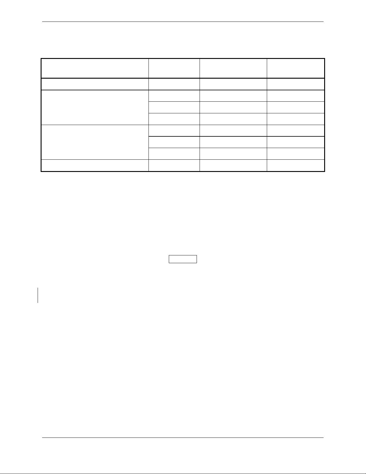
Table 2-1. GPA 65 Minimum Wiring Requirements
Line
Number of
Pins/Wires
Length of Wire
Wire Gauge
Specification
+35V 2 Up To 45' #24 AWG
2 Up To 45' #24 AWG
+6V
1 Up To 30' #22 AWG
1 Up To 20' #24 AWG
2 Up To 45' #24 AWG
-5V
1 Up To 30' #22 AWG
1 Up To 20' #24 AWG
Ground 3 Up To 45' #24 AWG
The contacts used to facilitate the use of #18 AWG wire for Aircraft Power and Aircraft Ground have
expanded-diameter barrels that extend out from the back of the standard D-sub connector body to
accommodate the larger diameter wire. Appropriate heat shrink tubing should be utilized to provide
sufficient insulation from surrounding contacts.
Ensure that routing of the wiring does not come in contact with sources of heat, RF or EMI interference.
Check that there is ample space for the cabling and mating connectors. Avoid sharp bends in cabling and
routing near aircraft control cables.
NOTE
All appliance to antenna cabling shall bundle top channels as a group and bottom
channels as a group to prevent incorrect wiring between top and bottom channels.
A visual inspection shall be performed to verify that all coaxial cables are connected properly, before
attempting to operate the equipment.
Page 2-6 GTS 8XX/GPA 65 Installation Manual
Revision 4TP 190-00587-00
2.4.1 Coaxial Cable
The GTS 800 requires two sets of coaxial cable assemblies and the GTS 820/850 requires three sets of
coaxial cable assemblies when a directional GA 58 antenna (or other Garmin approved antenna) is used
for both top and bottom. Each set consists of four coaxial cable assemblies.
Each set of four cables must be assembled using the same type of coaxial cable in order to meet phase and
attenuation matching requirements. In order for the system to operate in compliance with manufacturer
specifications, the coaxial cable assemblies must not exceed the attenuation specifications as stated in this
document. This section explains in further detail the coaxial cable and termination requirements.
2.4.1.1 GTS 800 Installations
NOTE
A monopole antenna is required if installing an optional bottom mounted antenna on all
fixed-gear aircraft. Retractable-gear aircraft can use either a monopole or a directional
bottom mounted antenna.
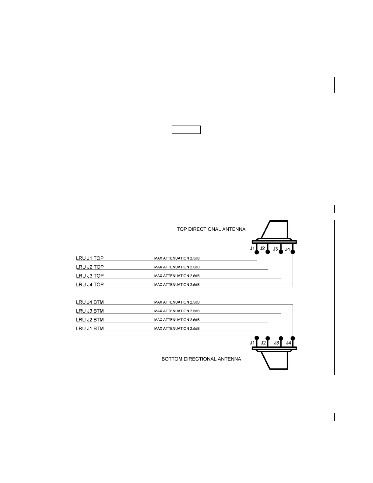
A GTS 800 installation with both top and bottom mounted directional antennas uses one set of coaxial
cables for the four GTS 800 TOP jacks (J1 TOP, J2 TOP, J3 TOP, J4 TOP) that are connected to the
corresponding top antenna jacks J1, J2, J3 and J4. A second set of coaxial cables are used for the four
GTS 800 BTM jacks (J1 BTM, J2 BTM, J3 BTM, J4 BTM) that are connected to the corresponding
bottom antenna jacks J1, J2, J3 and J4. Each cable assembly shall not exceed the maximum attenuation
of 2.5dB at 1090MHz as shown in Figure 2-1.
Figure 2-1. GTS 800 Installation with Top and Bottom Directional Antennas
If an optional bottom mount monopole antenna is installed, a single coaxial cable must be used to connect
the GTS 800 bottom jack J1 BTM to the monopole antenna jack. The coaxial cable assembly shall not
exceed the maximum attenuation of 2.5dB at 1090MHz as shown in Figure 2-2 and stated in Table 2-4.
Each of the remaining GTS 800 bottom jacks (J2 BTM, J3 BTM, J4 BTM) are to be terminated using a
QMA 2 watt termination as specified in Table 2-2.
GTS 8XX/GPA 65 Installation Manual Page 2-7
190-00587-00 Revision 4TP
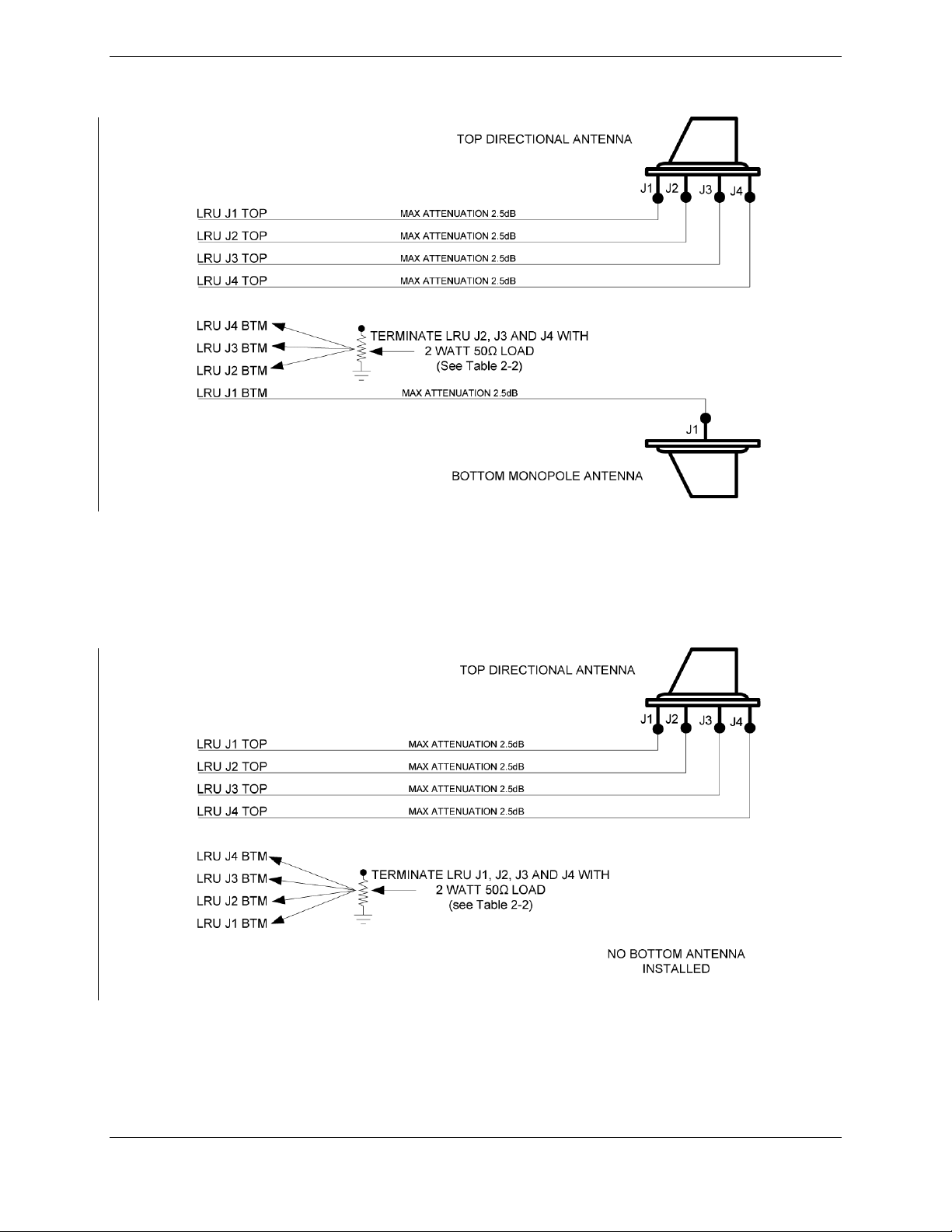
Figure 2-2. GTS 800 Installation with Top and Bottom Monopole Antennas
If no bottom mount antenna is installed, each of the GTS 800 bottom jacks (J1 BTM, J2 BTM, J3 BTM
and J4 BTM) must be terminated with a QMA 2 watt termination as specified in Table 2-2 and shown in
Figure 2-3.
Figure 2-3. GTS 800 Installation with Top Directional Antennas and No Bottom Antenna
Page 2-8 GTS 8XX/GPA 65 Installation Manual
Revision 4TP 190-00587-00
 Loading...