

Garmin 0104400, 0104450 Users Manual
GNS 430(A) Pilot’s Guide and Reference
190-00140-00 Rev. P
12-11
SECTION 12
ADDITIONAL FEATURES
12.2 TRAFFIC ADVISORY SYSTEMS (TAS)
Introduction
All information in this section pertains to the display
and control of the Garmin GNS 430/GTS 800 interface.
NOTE: This section assumes the user has
experience operating the GNS 430 and the
GTS 800.
NOTE: References to the GTS 800 throughout
this document refer equally to the GTS 820 and
GTS 850 unless otherwise noted.
System Description
The GNS 430 provides an optional display interface for
the GTS 800 Trafc Advisory System (TAS). The GTS 800
monitors the airspace surrounding an aircraft, and advises
the ight crew where to look for transponder-equipped
aircraft that may pose a collision threat.
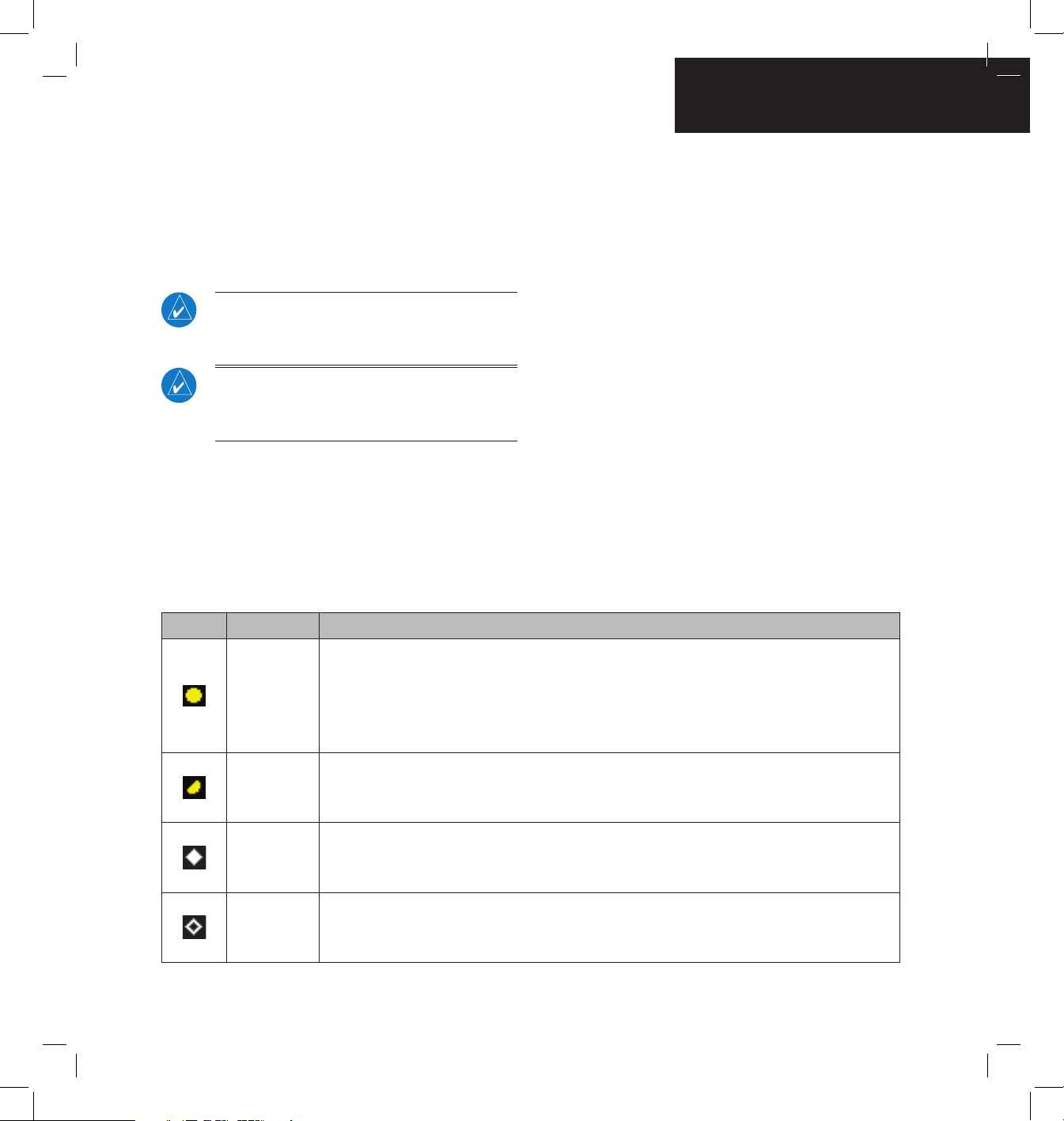
Symbol Traffic Type Description
Traffic
Advisory (TA)
A TA (Traffic Advisory) is generated when the GTS 800 predicts that an intruder aircraft may
pose a collision threat. A solid yellow circle represents an intruder aircraft that is on a course
that projects to intercept (defined by a 0.5 nm horizontal radius and a relative altitude of
± 500 ft) the pilot’s current course within 34 seconds. A TA consists of the traffic symbol and
an aural alert (e.g., “traffic, 12 o’clock, high, 3 miles”).
Out-ofRange Traffic
Advisory
This solid yellow half circle appears (on the outer range ring) under the same conditions and
has the same urgency as a TA. Its appearance differs from the TA only to signify that the
intruder is outside of the current range of the Traffic Page.
Proximity
Advisory (PA)
Proximity Advisories (PA) are displayed as solid white diamonds. PAs are defined as traffic
within the 6.0-nm range, within ±1200 ft. of altitude separation, and are not a traffic advisory
(TA).
Other Traffic
Symbol
This symbol (hollow white diamond) represents traffic detected within the selected display
range that does not meet the criteria for a TA or a PA and does not pose an immediate collision
threat.
Table 12-4 TAS Symbology
The GTS 800 is an active trafc advisory system that
operates as an aircraft-to-aircraft interrogation device.
When the GTS 800 receives replies to its interrrogations, it
computes the responding aircraft’s range, bearing, relative
altitude, and closure rate; it then plots the traffic location
and predicts collision threats.
Traffic Symbology
Trafc information from the GTS 800 is displayed on
the GNS 430 unit using TAS symbology (Table 12-4) on
a dedicated Trafc page, and on the moving Map Page.
The displayed traffic information generally includes the
relative range, bearing, and altitude of intruder aircraft.
The GTS 800 also generates aural announcements heard
on the cockpit audio system.
GNS 430(A) Pilot’s Guide and Reference
190-00140-00 Rev. P
12-12
SECTION 12
ADDITIONAL FEATURES
Altitude deviation (Figure 12-20) from own aircraft
altitude is displayed (in hundreds of feet) for each target
symbol. If traffic is above own aircraft altitude the
deviation is shown above the target next to a ‘+’ symbol.
If traffic is below own aircraft altitude the deviation is
shown below the target next to a ‘-’ symbol.
Altitude trend (Figure 12-20) is displayed as an up
arrow (> +500 fpm), down arrow (< -500 fpm), or no
symbol if less than 500 fpm rate in either direction.
Figure 12-20 Traffic Symbol Components
Altitude
Deviation
Altitude
Trend
Traffic
Type
Aural Alerts
A TA consists of a displayed trafc symbol (solid yellow
circle) and an aural alert. The aural alert announces
“traffic”, followed by the intruder aircraft’s position,
altitude relative to own aircraft (“high”, “low”, or “same
altitude”), and distance from own aircraft; e.g. “trafc, 12
o’clock, high, 3 miles”.
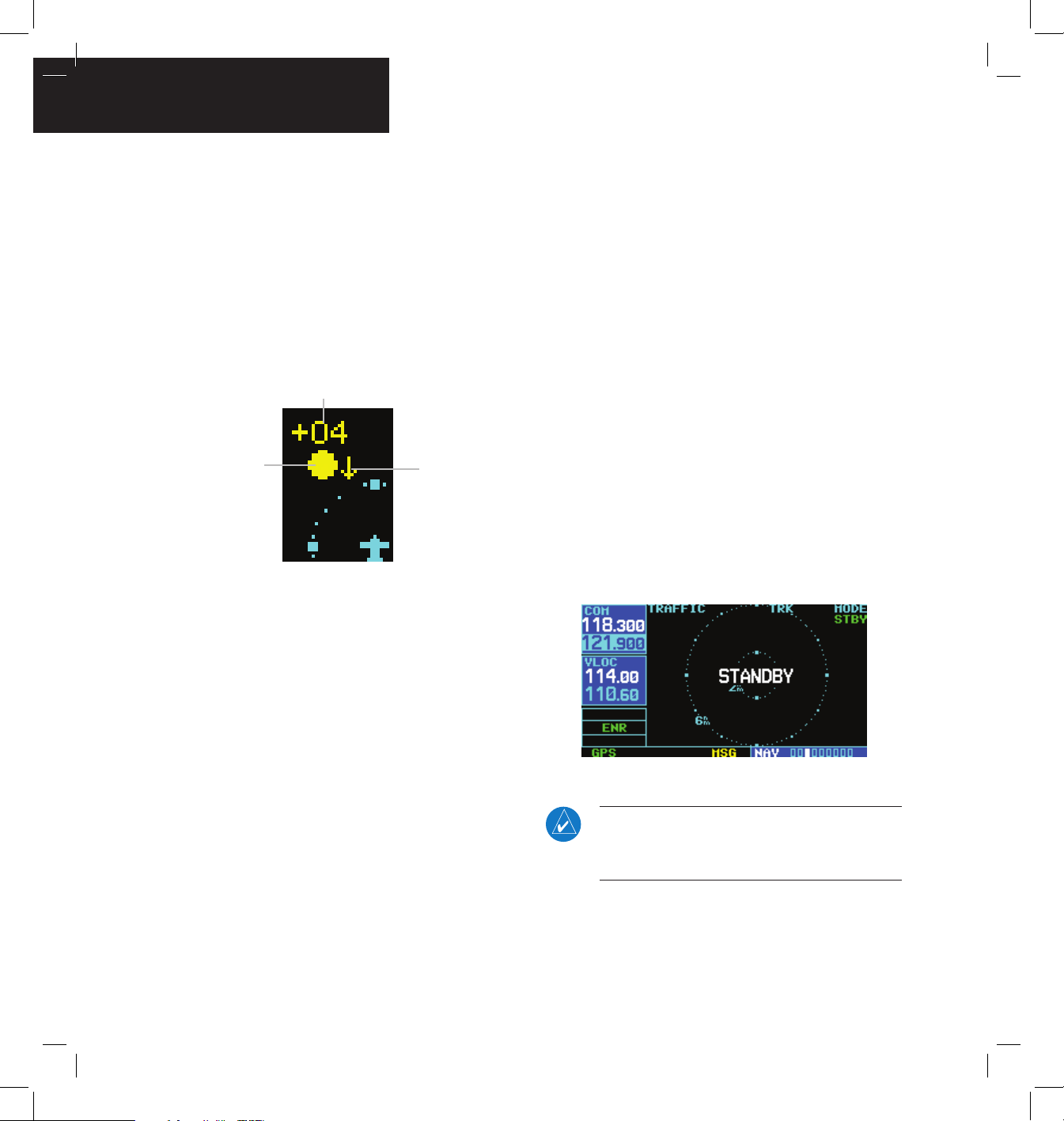
Power-up Self-Test
Check for the following test criteria on the Trafc Page
during power-up:
• If the GTS 800 passes the power-up test; and
the aircraft both has a squat switch and is on the
ground, the Standby Screen is displayed (Figure
12-21).
• If the GTS 800 passes the power-up test and the
aircraft both has a squat switch and is airborne,
the Trafc Page is displayed on the 6-nm display
range and in the normal altitude display mode.
• If the GTS 800 passes the power-up test and the
aircraft does not have a squat switch, the Standby
Screen is displayed (Figure 12-21).
• If the GTS 800 fails the power-up test (as
indicated by a FAILED screen), the GTS 800 is
inoperable, see the GTS 800 Installation Manual
for detailed information on Failure Response.
Figure 12-21 Standby Mode
NOTE: When the system is in standby, the
GTS 800 does not transmit, interrogate, or track
intruder aircraft.

GNS 430(A) Pilot’s Guide and Reference
190-00140-00 Rev. P
12-13
SECTION 12
ADDITIONAL FEATURES
Tracking intruder aircraft
1) Press the small right knob to activate the
cursor and highlight ‘STBY’.
2) Turn the small right knob to select ‘OPER’.
3) Press the ENT Key to confirm operating mode
and begin tracking intruder aircraft.
NOTE: The FAILED message is displayed when
the system detects an error that prohibits further
traffic display operation.
User-initiated Test
In addition to the power-up test, the GTS 800
performs self-tests during normal operation. A self-test
is performed once per minute to verify that the antenna
is connected. Also, a calibration is performed at varying
intervals based on time and temperature. A user-initiated
test of the GTS 800 interface can also be performed.
NOTE: A user-initiated test can only be performed
when in standby or failed mode.
Performing a user-initiated test:
1) Turn the small right knob to select the Traffic
Page.
2) From the Traffic Page, press the MENU Key to
display the Page Menu.
3) Turn the small right knob to select ‘Self
Test?’.
4) Press the ENT Key.
Switching Between Standby and Operating
Modes
The unit must be in operating mode for traffic to be
displayed. The ability to switch out of standby into operating
mode on the ground is especially useful for scanning the
airspace around the airport before takeoff. Operating Mode
is conrmed by the display of ‘OPER’ in the upper righthand corner of the Trafc Page (Figure 12-22).
Switching to Operating Mode from Standby
Mode:
1) Press the small right knob to activate the
cursor and highlight ‘STBY’.
2) Turn the small right knob to select ‘OPER?’.
3) Press the ENT Key to confirm and place the
GTS 800 in operating mode, the GTS 800
switches out of standby into the 6-nm display
range.
NOTE: If the aircraft has a squat switch and the
pilot does not manually switch out of standby, the
GTS 800 will automatically switch out of standby
8 to 10 seconds after takeoff.
Switching to Standby Mode from the Traffic
Page:
1) Press the small right knob to activate the
cursor and highlight ‘OPER’.
2) Turn the small right knob to select ‘STBY?’.
3) Press the ENT Key to confirm and place the
GTS 800 in standby mode.
NOTE: If the aircraft has a squat switch, STBY is
not displayed while the aircraft is airborne but
will go into standby 24 seconds after landing.
This delay allows the GTS 800 to remain out of
standby during a touch-and-go maneuver.
 Loading...