

Page 1

Sonalysts Combat Simulations
Dangerous Waters™
User Manual
Page 2

The software and documentation are © 2004 Sonalysts, Inc. All rights
reserved. Sonalysts and “Sonalysts Combat Simulations – Dangerous
Waters” are trademarks or registered trademarks of Sonalysts, Inc. The
Naval Institute Guide to Combat Fleets of the World © 2002 by the U.S.
Naval Institute, Annapolis, Maryland, All rights reserved and the Naval
Institute Guide to World Naval Weapons Systems © 1997 by the U.S. Naval
Institute, Annapolis, Maryland, All rights reserved are trademarks of the
U.S. Naval Institute and may be registered in certain countries. All other
trademarks are the property of their respective owners.
Page 3

MANUAL SECTIONS
This manual is divided into sections. Each section contains its
own Table of Contents.
Section 1: Install Guide 1-1
Section 2: Welcome/Getting Started 1-2
Section 3: Main Menu 3-1
Section 4: Multiplayer 4-1
Section 5: Training 5-1
Section 6: Navigation Station 6-1
Section 7: FFG Stations 7-1
Section 8: MH-60R Stations 8-1
Section 9: P-3C Orion Stations 9-1
Section 10: Kilo Stations 10-1
Section 11: Akula Stations 11-1
Section 12: Seawolf Stations 12-1
Section 13: 688(I) Stations 13-1
Appendices
Appendix A: Acronyms A-1
Appendix B: Terms B-1
Appendix C: Submarine Max and Mins C-1
Appendix D: In-Game Sensors D-1
Appendix E: Credits E-1
i
Page 4

LICENSE
This License does not provide you with title to or ownership of the software
program “Sonalysts Combat Simulations – Dangerous Waters”, (the
“Software”) but only a right of limited use of the Software, and ownership of
the media on which a copy of the Software is reproduced. The Software,
including its source code, is, and shall remain, the property of Sonalysts, Inc.
You may make one copy of the Software solely for back-up purposes,
provided that you reproduce all proprietary notices (e.g., copyright, trade
secret, trademark) in the same form as in the original and retain possession
of such back-up copy. The term "copy" as used in this License means any
reproduction of the Software, in whole or in part, in any form whatsoever,
including without limitation, print-outs on any legible material, duplication in
memory devices of any type, and handwritten or oral duplication or
reproduction. The manual may not be copied, photographed, reproduced,
translated, or reduced to any electrical medium or machine-readable form,
in whole or in part, without prior written consent from Sonalysts. All rights
not specifically granted in this Agreement are reserved by Sonalysts.
You shall not, in any way, modify, enhance, decode, or reverse engineer the
Software. User-created scenarios may be distributed free of charge, but shall
not be sold, licensed, or included as part of any package or product that is
sold or licensed, without the prior written consent of Sonalysts. You may not
rent or lease the Software or related materials.
You may permanently transfer the Software and related written materials if
you retain no copies, and the transferee agrees to be bound by the terms of
this License. Such a transfer terminates your License to use the Software and
related materials.
LIMITED WARRANTY
Sonalysts and Battlefront.com warrant to the original purchaser that the
media on which the Software is recorded is free from defects in workmanship
and material under normal use and service for 90 days from the date of
delivery of the Software. This warranty does not cover material that has been
lost, stolen, copied, or damaged by accident, misuse, neglect, or
unauthorized modification.
Sonalysts’ and Battlefront.com’s entire liability and your exclusive remedy
shall be, at Battlefront.com’s option, either return of the price paid, or
replacement of the media which does not meet the limited warranty described
above. The media must be returned to Battlefront.com with a copy of your
purchase receipt. Any replacement Software media shall be subject to this
same limited warranty for the remainder of the original warranty period, or
thirty days, whichever is longer.
LIMITATION OF LIABILITY
SONALYSTS AND BATTLEFRONT.COM MAKE NO OTHER WARRANTY OR
REPRESENTATION, EXPRESS, IMPLIED, OR ANY WARRANTY ARISING FROM
A COURSE OF DEALING, TRADE USAGE, OR TRADE PRACTICE WITH
RESPECT TO THE SOFTWARE OR RELATED MATERIALS, THEIR QUALITY,
PERFORMANCE, MERCHANTABILITY, NON-INFRINGEMENT, OR FITNESS FOR
A PARTICULAR PURPOSE. AS A RESULT, THE SOFTWARE AND RELATED
ii
Page 5

MATERIALS ARE LICENSED “AS IS.” IN NO EVENT WILL SONALYSTS OR
BATTLEFRONT.COM BE LIABLE FOR ANY SPECIAL, INCIDENTAL, OR
CONSEQUENTIAL DAMAGES RESULTING FROM POSSESSION, USE, OR
MALFUNCTION OF THE SOFTWARE AND RELATED MATERIALS. SOME
STATES DO NOT ALLOW LIMITATION AS TO HOW LONG AN IMPLIED
WARRANTY LASTS AND/OR EXCLUSIONS OR LIMITATION OF INCIDENTAL OR
CONSEQUENTIAL DAMAGES SO THE ABOVE LIMITATIONS AND/OR
EXCLUSION OF LIABILITY MAY NOT APPLY TO YOU. THIS WARRANTY GIVES
YOU SPECIFIC RIGHTS AND YOU MAY ALSO HAVE OTHER RIGHTS WHICH
VARY FROM STATE TO STATE.
iii
Page 6

iv
Page 7
SECTION 1
INSTALLATION GUIDE
Section 1: Installation Guide
1-1
Page 8

1: INSTALLATION GUIDE
S
YSTEM REQUIREMENTS
MINIMUM SPECIFICATIONS
Windows 98SE/ME/2000/XP
550Mhz processor
128 MB RAM
Eight-speed CD-ROM drive
Direct 3D compliant Video Card with 32MB RAM, (with DirectX 9.0b
compatible drivers)
Sound Card with DirectX 9.0b compatible drivers
Desktop Resolution of 800x600 @ 16-bit color depth
590MB hard-drive space for installation
Internet or LAN connection required for multiplayer
RECOMMENDED SYSTEM
The following upgrades from the minimum specifications are
recommended:
1GHz+ processor
256 MB RAM
Direct 3D compliant Video Card with 64MB RAM, (with DirectX 9.0b
compatible drivers)
1GB hard-drive space for installation
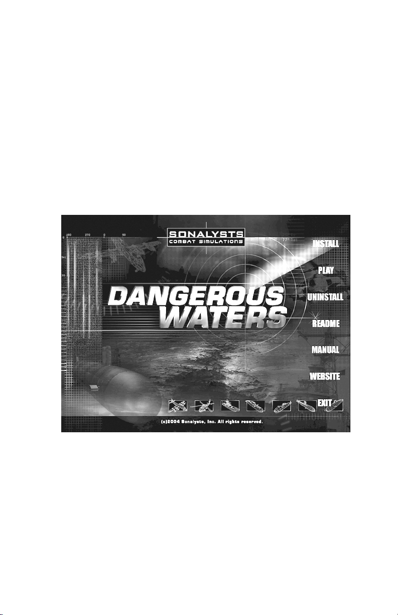
TO INSTALL S.C.S. – DANGEROUS WATERS
1. Insert S.C.S. - Dangerous Waters CD disk #1 in your CD-ROM drive.
When the install wizard appears, click INSTALL.
2. The Dangerous Waters Setup Wizard appears. Click NEXT to proceed
to the next step. (You can click CANCEL at any point to exit the Setup
Wizard.)
3. The Choose Destination Location window appears. Click NEXT to
install the game to the default location or select BROWSE to select and
alternative location, then click NEXT.
4. The Setup Type window appears. You must select FULL or TYPICAL
before you can proceed. Click NEXT.
5. The Select Program Folder window appears. Click NEXT to install the
game to the default Program File location or click BROWSE to select
an alternate location, then click NEXT.
Section 1: Installation Guide
1-2
Page 9

6. The Start Copying Files Window appears providing you with an
opportunity to review your selections for type and locations before
starting the copy process. To change your selections, click BACK. Click
NEXT to continue.
7. A progress bar appears indicting that the files are being copied to your
hard drive. Partway through this process you are prompted to insert
disk #2. Remove disk #1, insert disk #2 then click OK.
8. Near the completion of the copy process you are prompted to insert
disk # 1 again. Remove disk #2, insert disk#1 then click OK.
9. You are prompted to add an icon to the desktop. Click YES or NO as
desired.
10. The Adobe Acrobat Reader information window appears. Click YES.
11. You are prompted to install Voice Command Recognition software.
Click YES or NO as desired.
12. You are prompted to install DirectX 9 if it is not installed. You must
install DirectX 9 to run S.C.S. – Dangerous Waters. You are informed if
DirectX 9 is already installed. Click OK.
13. The Initial Skill Level selection window appears. You must select
Novice or Advanced settings as described in the wizard to continue.
Click NEXT.
14. The InstallShield Wizard Complete window appears. Click FINISH.
Section 1: Installation Guide
1-3
Page 10

Section 1: Installation Guide
1-4
Page 11
SECTION 2
WELCOME
GETTING STARTED
Section 2: Welcome / Getting Started
2-1
Page 12

2: WELCOME/GETTING STARTED .............................................................2-3
CONTROLLABLE PLATFORMS .................................................................2-3
U.S. PLATFORMS ............................................................2-3
Oliver Hazard Perry (FFG-7) Class.........................2-3
MH-60R Multi-mission Helicopter ........................... 2-4
P3-C Orion.............................................................. 2-4
Seawolf (SSN 21) Class ......................................... 2-4
Los Angeles Improved (SSN 688(I)) Class .............2-5
RUSSIAN PLATFORMS ......................................................2-5
Kilo SS & Kilo Improved SS Classes ...................... 2-5
Akula 1 Improved SSN & Akula II SSN Classes .....2-5
CHINESE PLATFORMS (PROC)......................................... 2-5
Kilo SS & Kilo Improved SS Classes ...................... 2-5
HOW TO USE THIS MANUAL ...................................................................2-6
ASSUMPTIONS IN MANUAL................................................. 2-7
Specific Options Settings ........................................ 2-7
Terms defined......................................................... 2-9
GAMEPLAY OVERVIEW..................................................................... 2-11
GAMEPLAY ................................................................... 2-11
Getting Started......................................................2-12
Autocrew............................................................... 2-13
Damage ................................................................ 2-13
Task Bar ............................................................... 2-13
Navigation Station (Brief Overview) ...................... 2-14
Voice Commands .................................................2-15
System Menu........................................................ 2-16
PLAYING FROM THE NAVIGATION STATION........................ 2-17
Section 2: Welcome / Getting Started
2-2
Page 13

2: WELCOME/GETTING STARTED
Now you can command a surface, subsurface or air platform all in one
game! S.C.S. - Dangerous Waters allows you to engage the enemy below
as the commander of an Oliver Hazard Perry Class Guided Missile Fast
Frigate, its MH-60R multi-mission helicopter or a P-3C Orion ASW/ASUW
aircraft. Prowl the ocean depths in a U.S. Seawolf or Improved Los Angeles
Class Nuclear Submarine or seek out enemy targets in a Russian Akula I
Improved or Akula II Nuclear Submarine or an ultra quiet Russian or
Chinese Kilo diesel sub!
Play the campaign from either the Blue (U.S. or U.S. and Russian alliance)
or Red vantage point (Chinese or Chinese and Russian alliance).
Multiplayer missions pit you against players commanding the most capable
submarines at sea or a deadly submarine hunter.
Multiplayer Multi-Station mode allows you to man a specific station aboard
a ship, plane or sub with other players taking the role of other
crewmembers on the same platform! See the Multiplayer section of this
manual.
As the Commander of your platform you can relinquish control of various
stations to your Autocrew or man all stations yourself. Give orders to your
crew via voice commands, use the handy menu commands from the Task
Bar or mouse commands in the Navigation Station. The Task Bar allows
you to perform many maneuvering tasks from any station.
Create your own missions in S.C.S. - Dangerous Waters powerful Mission
Editor. Information from the United States Naval Institute is available on all
military ships and planes modeled in the game.
CONTROLLABLE PLATFORMS
Controllable platforms include sub classes from three countries and U.S.
Navy ASW surface and air platforms. The following classes are controllable
in S.C.S. - Dangerous Waters.
U.S. PLATFORMS
Oliver Hazard Perry (FFG-7) Class
Small, sleek and fast, Oliver Hazard Perry class guided missile frigates
(FFGs) are uniquely capable warships, commonly referred to as a "Fleet
work horse," to protect shipping, with particular emphasis as an AntiSubmarine Warfare (ASW) combatant. This ship class was designed to be
cost efficient and therefore lacks a true multi-mission capability.
Nonetheless, these frigates are a tough ship capable of withstanding
considerable damage as demonstrated by the USS Stark surviving a hit by
two Exocet cruise missiles and the survival of USS Samuel B. Roberts after
suffering a mine detonation. A significant combat upgrade for these ships
came about from embarking multi-mission helicopters to extend the combat
reach in terms of both weapons and sensor capabilities. This surface
Section 2: Welcome / Getting Started
2-3
Page 14

combatant is capable of engaging and destroying targets on land, in the air,
and on the sea; remaining at sea for extended periods of time, and
continuing to operate in very rough sea conditions.
MH-60R Multi-mission Helicopter
The MH-60R is an advanced multi-mission helicopter equipped with state of
the art electronics and sonar including Multi-Mode Radar, Electronic
Support Measures, and AQS-22 airborne low frequency dipping sonar
(ALFS). Its Penguin missiles can engage surface combatants and its
Hellfire missiles make it a threat to small surface craft and land targets
alike! With its dipping sonar and the latest in sonobuoy processing the MH60R can quickly detect, localize and attack enemy submarines with Mk 46
or Mk 50 torpedoes!
Its up to date sensors and its mission specific weapon loadouts make this
an excellent combat asset that greatly expands the range of its host surface
combatant.
The MH-60 R is a controllable platform and is embarked on the Perry class
(FFG-7) and other U.S. ships in S.C.S. - Dangerous Waters.
P3-C Orion
While its primary mission was originally anti-submarine warfare (ASW) and
maritime patrol, the four-engine turboprop P-3C Orion has increasingly
become a multi-mission platform as evidenced by its invaluable support of
Operation Iraqi Freedom where it provided battlefield surveillance! Utilizing
its long-range and the ability to remain on station for long periods of time,
the P-3C patrolled the battlespace and provided instantaneous reports to
troops on the ground.
Mission roles for the P-3C in addition to ASW now include anti-surface
warfare (ASUW), carrier battle group support, over-the-horizon (OTH)
surveillance and targeting, interdiction operations, and littoral warfare. To
assist in its anti-surface role, new equipment has been installed including
imaging radar and electro-optic sensors. ASW equipment in the P-3C
includes magnetic anomaly detection (MAD) and sonobuoys including
directional frequency and ranging (DIFAR) capability.
The P-3C can carry a variety of weapons depending on its assigned
mission. Weapons include Mk 46 and Mk 50 torpedoes, and SLAM-ER and
Maverick missiles for strike warfare. Mines can also be carried.
Seawolf (SSN 21) Class
Countering the threat of the ultra-quiet non-nuclear subs acquired by third
world countries is now a primary mission of U.S. nuclear attack submarines.
This state-of-the-art U.S. attack submarine is the quietest nuclear powered
submarine currently deployed by any country. With its superior stealth, a
tactical speed higher than any other U.S. submarine, and its hardened sail,
Seawolf stands ready to tackle missions as varied as the insertion of
Special Forces to attacking threats under the polar ice cap. Her Tomahawk
missiles make her a threat to inland targets up to 1,400 nm away and her
Mk 48 ADCAP torpedoes are lethal to subs and ships alike.
Section 2: Welcome / Getting Started
2-4
Page 15

Los Angeles Improved (SSN 688(I)) Class
The “backbone of the fleet”, the 688(I) class sub is one of the quietest
submarines in operation today and is armed with state-of-the-art weaponry
including Tomahawk land attack missiles and Mk 48 ADCAP torpedoes. Its
hardened sail and bow planes make it available for missions under the ice.
688(I) class subs are available in sufficient numbers to ensure availability
for missions around the world.
RUSSIAN PLATFORMS
Kilo SS & Kilo Improved SS Classes
Dubbed “The Black Hole” by NATO personnel for its uncanny ability to
disappear, the ultra quiet Kilo and its crew stand poised to protect littoral
water from intrusion by enemy submarines and surface ships. Its six
torpedo tubes can be loaded out with the latest in Russian wire-guided and
wake homing torpedoes as well as anti-sub, anti-ship and land attack
missiles making it a deadly opponent. With its anechoic hull coating, two
120-cell batteries providing 9.700 kw/hr and an air regeneration system
providing enough breathable atmosphere for 260 hours of operations with a
full crew, this is not your grandfather’s World War II diesel submarine!
Akula 1 Improved SSN & Akula II SSN Classes
Russia’s counterpart to the U.S. Los Angeles Class, the Improved Akula-I
Class submarine is nearly as quiet as the 688(I). With six additional tubes
external to the pressure hull, it is capable of carrying additional weapons or
decoys.
Quieter than the Akula I Improved the Akula II is the quietest nuclear
powered Russian submarine in existence. At low speed it is reported to be
as quiet or quieter than the United States Improved Los Angeles class
submarine. Also armed with six additional external tubes for weapons or
countermeasures, the Akula-II is a formidable opponent.
CHINESE PLATFORMS (PROC)
Kilo SS & Kilo Improved SS Classes
Uniquely suited for operations in the South China and East China Seas, five
Russian built Kilo submarines significantly enhance the People’s Liberation
Army Navy (PLAN’s) attack submarine fleet. One of the quietest
submarines in operation when operating on battery, it is capable of
detecting an enemy sub at a range far greater than the range at which it
can be detected itself. This extremely capable sub with its loadout of antisub and anti-surface torpedoes and Russian built missiles stands ready to
confront hostile naval forces and deny them access to sea lanes, and costal
and naval facilities!
Section 2: Welcome / Getting Started
2-5
Page 16

HOW TO USE THIS MANUAL
This manual is divided into the following sections. (A separate Mission
Editor manual is found in electronic format on S.C.S. – Dangerous Waters
CD 1 in the Manual folder.
Install Guide: Provides minimum and suggested system requirements and
step-by-step instructions for installing S.C.S. – Dangerous Waters.
Welcome/Getting Started: This is the section you are reading now. This
section defines terms as used in the manual and outlines game settings
assumed in the manual. If your settings do not match those assumed, your
experience will be different than those described in here. This
provides a very brief overview of the game, how to get started and an
overview of game elements that are common across all controllable
platforms. You are also directed to the location of full explanations for game
elements when appropriate.
Main Menu: Main Menu options with the exception of Mission Editor and
Multiplayer are described in full here. Mission Editor is fully explained in a
separate manual included on your game CDs. Multiplayer is described in its
own section in this manual.
Multiplayer: How to host or join a multiplayer game is explained. Playing
the game in Multi-Station mode is also described. In Multi-Station mode
several players work together within a single platform, with each person
manning a specific station or suite of stations.
Training: This section provides background needed to effectively use sonar
sensors and the TMA station.
Sonar School: An introduction to sound transmission and sonar terms
and concepts. A description of how to use the Sonobuoy Display
windows (Grams) is found here.
TMA Basics: The principles of Target Motion Analysis (TMA) and how
it works to create a firing solution are covered here.
Navigation Station: The game starts in the Navigation Station regardless
of the platform you are commanding. The Navigation Station functions
virtually the same regardless of Ownship selection. The basics of
Navigation Station functionality are covered here. All other stations are
covered separately according to platform.
FFG Stations: Explains all FFG stations and functionality.
MH-60R Stations: Explains all MH-60R stations and functionality
P-3C Orion Stations: Explains all P-3C Orion stations and functionality
Kilo Stations: Explains all Kilo stations and functionality.
Akula Stations: Explains all Akula stations and functionality.
section also
Section 2: Welcome / Getting Started
2-6
Page 17

Seawolf Stations: Explains all Seawolf (SSN 21 Class) stations and
functionality.
688(I) Stations: Explains all 688(I) stations and functionality
Appendix A: Acronyms
Appendix B: Terms
Appendix C: Submarine Max and Mins
Appendix D: Ownship Sensor Names
Appendix E: Credits: A list of the people who created and contributed to
the production of S.C.S. – Dangerous Waters
Mission Editor: S.C.S. – Dangerous Waters ships with the robust Mission
Editor used to create the campaign and all missions in the game. The S.C.S
– Dangerous Waters Mission Editor User Manual is provided in electronic
(pdf) format in the Manual Directory on S.C.S – Dangerous Waters CD #1.
ASSUMPTIONS IN MANUAL
This section defines terms as used in the manual. The writer assumes
specific Options settings are selected in the Options>Game and Crew
screens. If different Game and Crew options are selected, the descriptions
seen here may not match your experience.
Specific Options Settings
You were forced to select Advanced or Novice Settings when you installed
S.C.S. – Dangerous Waters. While learning the game neither mode is
perfect. This manual assumes the specific settings for Game and Crew
Options as noted below.
Crew Options Settings
This manual describes what the player must do to use each station;
therefore, it assumes all Autocrew are off. If you have turned on any of your
Autocrew your experience will not be what is described within this manual.
From the Main Menu click Options then Crew. Click the square in
front of the type of platform you are commanding to select the
Autocrew options for that Platform. Click Defaults (Advanced).
This turns off all Autocrew for that platform.
Note: There is no Autocrew option for Auto Pilot for the P-3C and the
MH-60R. Because flying is never your primary tasking in air
platforms, Auto Pilot is on by default. When you fly the P-3C or MH60R with a joystick you must switch the Auto Pilot to OFF; however,
the Auto Pilot continues to work until you move the joystick. As soon
as you leave that station to attend to your tasking on other screens,
the Auto Pilot reverts to ON. Turn it OFF again when you return to
the Pilot Station. See Main Menu/Options/Crew for information on
Autocrew for each platform.
Section 2: Welcome / Getting Started
2-7
Page 18

Game Options Settings
While many game options can be considered cheats, some reflect realistic
settings. Selecting Novice Game setting can enhance your enjoyment of the
game while learning, by speeding up weapon and aircraft launch times and
reducing the time needed to repair damage.
If you selected Advanced settings at install or have tweaked any of your
Game Options settings we recommend clicking Defaults (Novice) in the
lower left of the Options>Game screen.
The manual assumes the following settings are selected in Options>Game
screen.
Show Dead Platforms ON: When ON destroyed platforms appear in 3D
and on the Nav Map whether you have detected the platform or not. This
feature is a cheat but provides you with feedback that you really have hit
your target when you have no way of knowing otherwise. While you are
learning the game, this feedback is reassuring that you are doing things
correctly. The dead platform is a Truth object. It represents the actual
identity of the platform and its actual location on the Nav Map and in the 3D
view when the symbol is selected. Its symbol is greyed on the Nav Map to
indicate it has been destroyed. You will continue to see the wire frame or
solution representations as detected by your own sensors as well. (See
Navigation Station/2D Navigational Map for in-depth information on the Nav
Map and its symbols.)
Show Truth OFF: When ON, symbols for all objects in the mission display
on the Nav Map, whether you have detected them or not. Each symbol
appears in the contact’s true location and reflects its accurate category and
alliance ID.
Show Allies OFF: When ON this is the equivalent of Show Truth for Allies.
The true locations and platform data for Ownside/friendly platforms appear
on the Nav Map.
Show Link Data ON: Commanders of the FFG, MH-60R and the P-3C will
see the Nav Map (and Geoplot) NTDS symbols for Link participants and all
contacts currently held by Link participants. Submerged subs will not see
Link data on the map at game start. Subs see Link data only when at
comms depth with the radio antenna extended or when the floating wire is
streamed and Ownship is shallow and traveling slow enough to receive
data. Once your sub is out of radio contact Link data are no longer updated.
See Navigation Station/2D Navigational Map section for in-depth
information on the Nav Map, its symbols and Link information.)
Weapon Quick Launch is ON: When OFF weapon reloads reflect realistic
times. When ON weapon reload and launch time units are in seconds
instead of minutes.
Aircraft Quick Launch ON: When OFF the time it takes to launch the
FFG’s helicopter reflects a realistic time interval. When ON, aircraft launch
time units are in seconds instead of minutes. (It takes a full hour to launch
your helo when it is not in Alert 30 if this feature is OFF.)
Section 2: Welcome / Getting Started
2-8
Page 19

Quick Damage Repair ON: When OFF damaged equipment repairs reflect
realistic times. When ON, repair time takes seconds instead of minutes.
Enable Wind OFF: When ON, any Wind Region defined in the mission by
the mission creator affects your Ownship aircraft or FFG navigation. Wind
speed and direction are noted in the Task Bar for aircraft and the FFG. See
Note below.
Enable Currents OFF: Any water region defined for a mission can
influence Ownship sub and ship navigation. There is no way to determine
the direction of currents. See Note Below.
Note: The wind and currents function basically the same. Wind
affects aircraft and surface ships and currents affect subs and ships.
When enabled, crosswinds or currents push Ownship off course.
Opposing winds or currents slow Ownship, while trailing winds or
currents speed it up. If you order an exact speed via the Task Bar,
your crew takes wind and currents into account in maintaining your
ordered speed, but if you give a specific engine order, your actual
speed may vary. Be aware that the speed readout on the Task Bar
shows forward speed through air or water, not speed over the
ground. If you've ordered an exact speed, your indicated speed may
be higher if you're driving into a wind or current, or lower if you're
riding with a trailing wind or current.
Enable Waveriding ON: When OFF, objects in the water in a high sea
state will not follow waves, but will stay straight and level. This may cause
models to submerge or float above the waves in 3D. This option should only
be disabled to lighten CPU load for performance reasons. For further
information on the Game options see Main Menu/Options/Game.
Default Keyboard Controls Settings
This manual assumes the default keyboard control settings are in effect. If
you have changed your hot key assignments in the Options>Controls page,
the keyboard commands listed in the manual will not be accurate. Click
Defaults at the bottom of the Options>Controls page to return any settings
you have changed to those shipped with the game.
Terms defined
In this manual the following terms are used as defined below:
General Terms
Click: Single left mouse button click
Right-click: Single right mouse button click
Platform Terms
Platform: Any ship, sub or aircraft
Controllable Platform: A ship, sub or aircraft that can be player
controlled in the game.
Ownship: Refers to the current controllable platform regardless of
category. (Controllable aircraft are also referred to as Ownship.)
Section 2: Welcome / Getting Started
2-9
Page 20

Ownside: All platforms assigned to your side by the mission creator.
688(I): Any controllable U.S. Improved Los Angeles class nuclear
submarine.
Akula: Any controllable Akula I Improved or Akula II class nuclear
submarine. All Akula game interfaces are the same. Their weapons,
top speed and noise levels differ.
FFG-7 or FFG: Any controllable U.S. Oliver Hazard Perry (FFG-7)
class surface ship.
Kilo: Any controllable Kilo Project 877 or Kilo 636 class (Russian or
Chinese) diesel submarine. All Kilo station interfaces are the same.
Their weapons, top speed and noise levels differ.
MH-60R or Helo: Any controllable U.S. MH-60R helicopter. The FFG’s
embarked MH-60R helo is also referred to as Helo even when it is not
player controlled.
P-3C or P-3: Any controllable U.S. P-3C Orion Update III AIM airplane.
Seawolf: Any controllable U.S. Seawolf (SSN 21) class nuclear
submarine.
VAB: Variable Action Button. Button text and functionality changes
when clicked. The FFG stations contain several VAB panels. The
Seawolf Button Matrix panels are variable action buttons.
In-Game Terms
Category: Refers to a type of platform for example surface,
subsurface, airplane (air) and helicopter (Helo.) Also refers to
stationary (land), weapon (torpedo), missile, and mine.
Confidence: Listed as Low, Medium or High, this refers to how
confident you are that your classification of the contact is accurate.
This is user assigned for contacts detected by Ownship sensors and
Link assigned for Link contacts.
Contact: Anything detected visually or by one of your ship’s sensors. A
contact is sometimes referred to as a track. A contact, or track, should
not be confused with a tracker.
Gram: Any of the small, rectangular display windows found in the FFG-
7, MH-60R or P-3C platforms that display narrowband and SSP data
transmitted from sonobuoys.
Hook: To select a track symbol on the Nav Map or a Geoplot screen.
Clicking on a track symbol “hooks” or selects it.
ID: When seen alone, this word refers to the presumed alliance of a
contact (Friendly, Hostile, Neutral, Unknown etc.)
Link: A network of platforms (ships and aircraft) that provide position
reports and sensor contact information via secure two-way UHF or HF
radio transmissions. This assumes satellite transmission so the entire
battlespace is covered if there are Link platforms in all corners of the
battlespace.
Section 2: Welcome / Getting Started
2-10
Page 21

Link Participant: All platforms (and land bases) reporting in your
current Link network. A Link is also modeled for Chinese and Russian
subs when they are Ownship.
Link Contact: A contact reported by a Link Participant.
Tag: A number automatically assigned by the FFG towed array to
detected frequencies. These numbers are internal to the Towed Array
and are not the same as a Track number (Track ID). (Show Tags in the
Nav Map refers to the assigned name of a platform.)
Track: Anything detected visually or by one of your ship’s sensors. A
track is sometimes referred to as a contact. A contact, or track should
not be confused with a tracker.
Track ID: Each sub interface and the FFG interface refers to
designated contacts with slightly different words. In this manual any
reference to an alphanumeric designation, a Contact ID, or a Track ID
refers to designations assigned when a contact is detected. This is a
letter with a number appended when commanding a sub (e.g. S01,
E01, R01, V01) or a four-digit number when controlling the FFG or
aircraft. Link participants report four-digit Track IDs. All controllable
platforms also have a Track, or Platform, ID.
Tracker: A device used to automatically follow a sonar signal to which
it is assigned. When a tracker is assigned to a sonar contact, called a
track, periodic updates on the contact’s bearing are sent to TMA. A
tracker is not a track, but it ‘tracks’ a track.
GAMEPLAY OVERVIEW
This section contains important information for the player who likes to jump
right in and start playing. If you only read one section of the manual, start
here!
GAMEPLAY
Mission tasking varies depending on the platform you are commanding.
Whether you are tasked to find and destroy an enemy target, drop off
Special Forces, engage or avoid an enemy platform, or track an ultra quiet
submarine, you must be familiar with your platform’s capabilities, sensors
and weapons systems in order to best accomplish the assigned task. The
stations for each platform are covered individually later in this manual.
Regardless of the type of platform you control (submarine, surface ship,
helicopter or maritime patrol plane) your goal is to use that platform’s
various sensors to detect and identify targets. Using the tools at your
disposal, you must classify the contact to determine whether it is a neutral,
enemy or friendly ship, sub or aircraft, or a pod of whales. If you are tasked
with destroying the contact you must determine its location and if
appropriate its course, and engage the target with an appropriate weapon.
Depending on the type of platform you choose to control, your sensors can
include active and passive sonar, sonobuoys or dipping sonar, Electronic
Support Measures (ESM or EW), a periscope or binoculars, Magnetic
Section 2: Welcome / Getting Started
2-11
Page 22

Anomaly Detector (MAD), or Radar, and Link data from other friendly
platforms in your area.
In every mission you are assigned at least one task considered critical. A
critical task must be completed to ensure a satisfactory mission outcome.
These tasks are laid out in the mission brief or assigned in messages
during gameplay and identified as Critical Goals in Mission Status and in
Mission Debrief. Some tasks are secondary in importance. These are
identified as non-critical goals.
You must complete assigned tasks while keeping your platform out of
harm’s way. You can man all stations yourself or, if desired, you can use
the Autocrew to assist you with detecting, classifying and targeting
contacts, but bear in mind they are not infallible.
Getting Started
1. Create a player name from the Sonalysts Combat Simulation –
Dangerous Waters Main Menu screen.
2. Click Missions.
3. Select a Single Mission Title and a controllable platform. Click OK.
See Main Menu/Missions/Platform Selection Window for
information on selecting a controllable platform.
4. Read the brief then select the weapon icon button at the bottom of the
screen.
5. From the Weapons Loadout screen ensure that your loadout is
appropriate for the mission tasking. If not, change it. Click OK
6. Click OK in the Brief screen to load the mission. The Mission opens in
the Navigation Station.
See Navigation Station for a full explanation of Nav Station
functionality. Information on the NTDS Symbols is contained there
along with other information important to gameplay.
7. Once in the mission, press the function keys to view all the stations or
use the pop-up Stations Menu on the far left of the Task Bar. (All
submarines in S.C.S. – Dangerous Waters carry shoulder launched
Surface to Air Missiles. The SAM launcher is accessed from the Sail
[F9] only when the sub is surfaced. The SAM Launcher screen is
unavailable when the sub is submerged.)
See the Task Bar section of the Stations Menu for the platform you
are controlling for full information about Task Bar functionality in
that platform.
8. Learning how the stations work is your first order of business. See the
Station Section of this manual appropriate for the platform you are
commanding.
9. Detect, mark, track and or destroy contacts or complete other tasks as
directed in the Mission Brief.
Section 2: Welcome / Getting Started
2-12
Page 23

10. Press [Esc] then select Mission Status to check your progress in
completing the mission goals.
11. When Mission Goals are complete, press [Esc] and select End Mission.
(To save the mission to complete at a different time select Save or
Save as.)
12. In the Mission Debrief Screen review the complete and incomplete
goals or click REPLAY to see a replay of the mission just completed as
seen from the Nav Map.
13. Click OK to return to the Main Menu. The debrief results for all
missions played by the current Player Name are available in the
Players Log.
Autocrew
Each platform has several Autocrew to assist you. The manual assumes
that all Autocrew are off for the purpose of explaining each station’s
functionality. However while you are learning one station it may be useful to
turn ON the Autocrew for other stations. See Main Menu/Options/Crew for a
brief description of all Autocrew. Each platform’s Autocrew functionality is
explained more fully at the end of each platform’s Stations section.
Damage
On occasion Ownship may incur damage from weapon impact, running
aground, collision or some other means. Depending on the platform, you
may receive a voice message or a text report may appear in the crew
message area.
Whenever damage occurs a ship system may be temporarily or
permanently out of commission depending on the extent of the damage and
the location. The Damage slider in the upper right corner of the station
slides out to reveal a wrench indicating that some portion of that station is
damaged and no longer functioning. A wrench icon replaces the regular
cursor over a button, gauge, switch etc if that portion of the system is
damaged and currently unusable.
Further information is found in the Damage report window in the Task Bar.
Unless instructed on a remedial course of action to repair the damage, for
instance come to Periscope Depth and ventilate, there is nothing you can
do to speed the damage recovery process short of turning on Quick
Damage Repair at game start. If damage can be repaired it occurs
automatically over time. Enabling Quick Damage Repair reduces the
amount of time required to complete the repair.
COMMON STATIONS AND GAME ELEMENTS
Some game stations, elements and functionality are the same regardless of
the platform you choose to command. A brief overview is found below.
Task Bar
The Task Bar is available at the bottom of all stations in the game and
provides a pop-up Stations Menu for switching to other stations and a pop-
Section 2: Welcome / Getting Started
2-13
Page 24

up Orders Menu for issuing common commands. The Task Bar also
provides a means for performing basic maneuvers and viewing a history of
damage reports, crew reports, radio messages and multiplayer chat
messages. Maneuvering shortcuts and a means for accelerating time in the
game are also available in the Task Bar.
Since subs, ships and aircraft have different stations and modes of
maneuvering, the pop-up Stations and Orders Menus and Maneuvering
Shortcuts are slightly different for each type of platform. The layout of the
Task Bar is the same regardless of platform.
See the Stations section for the desired platform for a description of its Task
Bar elements.
Navigation Station (Brief Overview)
The Navigation station is made up of three distinct areas: the 2D Navigation
Map (Nav Map), the 3D View, and the Digital Data Indicator (DDI). The
position of the Nav Map and the 3D View can be swapped or hidden by
using the controls in the upper right corner of the station. For a full
description of all aspects of the Navigation Station see the Navigation
Station section of this manual.
2D Navigation Map
The game opens at the Navigation Station, or the Nav. Here you see the
Nav Map, a 2D map of the battle space. (You must scroll to see the entire
space.)
NTDS Symbols: Once a contact is detected by one of your sensors or the
Link it appears as a Naval Tactical Display System (NTDS) symbol on the
Nav Map and it is assigned a track number used by the ships’ systems
when targeting that contact. Since all sensors report a detected contact and
the Link reports contacts, in some cases two or more symbols may overlay
one another if all reporting sensors agree as to the location. Press [Tab] to
move between the contacts and view the DDI information for each
individual contact. (See Navigation Station/2D Navigation Map/NTDS
Symbols and Navigation Station/2D Navigation Map/Contact Designations
for information on the map symbols and track numbering system used in
S.C.S. – Dangerous Waters.)
Link Data: If you are commanding the FFG or one of the aircraft in the
mission you will initially see Ownship and then all members of your Link and
within a few seconds will also see all contacts reported by the Link. If you
are commanding a submerged submarine you see only the Ownship
symbol. Because you are not in contact with the Link when submerged you
see no Link contacts. To see Link participants and their reported contacts,
come to communications depth and extend the radio mast or stream the
floating wire from the Radio/ESM station. Each sensor that detects a
contact creates a contact symbol on the Nav Map and a contact ID for the
detection, therefore multiple symbols will be present for a contact held by
more than one sensor. In the subs and the FFG contacts detected by some
of Ownship sensors can be merged in TMA to better localize the contact
Section 2: Welcome / Getting Started
2-14
Page 25

and clean up the map. (See Appendix C: Submarine Max and Mins for a
listing of Comms Depth for all subs.)
3D View
The Navigation Station also contains a 3D window, or 3D View, for viewing
a 3D model of a selected or ‘hooked’ contact. Until a contact is classified it
appears only as a wire frame object or Area of Uncertainty (AOU) in the 3D
View. Once you classify the contact (or it has been classified by the Link or
the Autocrew) it then appears in the 3D view as a 3D model of that class.
Because contacts can be detected both by the Link and by your own
sensors it is likely that in some cases two 3D objects will appear close
together in the 3D View. See Navigation Station/3D View for more
information.
DDI
Known information on a selected contact is available in the Digital Data
Indicator (DDI) area of the screen. Complete information on the DDI is
found in Navigation Station/Digital Data Indicator (DDI).
Classify Contact Dialog
Once you have detected a contact it is important to determine its class and
alliance to ensure that you do not target friendly or neutral platforms. By
using the libraries available in various stations on all controllable platforms
you can determine the classification of unknown contacts.
Once you have determined the class of a contact and have a guess as to its
alliance you can designate the contact’s classification from the Nav Map
using the Classify Contact … dialog.
On the Nav Map click the desired contact then right-click on the
contact to display the Contact Menu. Select Classify Contact…
You must determine the correct classification to enter by using information
gathered at other stations. The stations utilized to determine the
classification of a contact differ between platform types. See Navigation
Station/2D Navigation Station/Contact Menu/Classify Contact As… for
complete information on using this feature.
Voice Commands
If you installed the speech recognition software (Microsoft's Speech
Recognition Engine 5.1) when you installed S.C.S. – Dangerous Waters
there are a variety of voice commands available during gameplay for each
controllable platform. The document Voice Commands.doc resides on the
S.C.S. – Dangerous Waters CD and contains a list of voice commands
recognized by the game.
Voice commands that correspond to keyboard commands can only be
used when the keyboard command is appropriate (e.g., they are
ignored when dialogs are visible.)
Voice commands that correspond to the Task Bar’s Orders Menu
commands can be used from any station.
Section 2: Welcome / Getting Started
2-15
Page 26

Voice Commands that correspond to a Nav Map right-click menu only
work when on the Nav Map.
Voice commands are only recognized during gameplay and not when
out-of-game screens such as the Options Menu are accessed during
gameplay.
You can train your speech engine by visiting the speech control panel
accessed via the Speech icon in the Windows 98, Windows 2000, Windows
ME or Windows XP control panel. You can also improve the accuracy of the
speech engine by adjusting the accuracy vs. performance slider in the
speech control panel.
Note: The speech recognition software is not compatible with
Windows 95. If you attempt to install the game on a Windows 95
platform, the option to install the speech recognition software is not
seen.
To utilize voice commands in the game:
1. In the Main Menu select Options>Sound.
2. Under the Speech heading select Enabled and, if desired, Always On.
Always On is only available when Enabled is checked. Both
Options are greyed if you do not have the Speech Engine
installed.
3. When only Enabled is selected on the Options>Sound page press and
hold the speech key while issuing a valid voice command. By default
the speech key is [W].
When the designated speech key is pressed during gameplay,
voice recognition is listening and the speech engine interprets
anything you say. When this key is released, voice recognition is
not listening and it ignores anything you say.
4. When Always On is selected on the Options>Sound page issue a valid
voice command as desired at any point during gameplay.
When the Always On option is checked, the designated speech
key is ignored and the speech engine is always listening to what
you say.
System Menu
The System Menu is available from any in-game station regardless of
platform by pressing [Esc] during gameplay or by selecting System Menu
from the Nav Map Menu. (Click the Nav Map to deselect any contacts then
right-click on the Nav Map surface to display the Nav Map Menu.)
The following options are available:
Resume: Leave the System Menu and resume gameplay.
Options: Displays the Options Menu.
USNI Reference: Displays the USNI Browser
Section 2: Welcome / Getting Started
2-16
Page 27

Mission Status: Displays the Mission Status screen giving you access
to your player name, the mission name, score, elapsed time, the
mission goals and a list of platforms destroyed up to this point in the
game.
Save: Displays the Save Dialog then returns to the game.
Save and Exit: Displays the Save Dialog then exits the mission.
End Mission: Exits the mission without providing an opportunity to
save the mission.
PLAYING FROM THE NAVIGATION STATION
With all Autocrew turned on it is possible to play some aspects of the game
from the Nav Station. Each platform has some elements that require your
presence at specific stations, but with careful planning, and the use of the
Task Bar’s Orders Menu and Maneuver shortcuts, Voice commands and
the Ownship and Contact right-click menus it is possible to attack hostile
platforms and perform a variety of tasks from the Navigation station. See
Navigation Station/Playing From the Nav.
Section 2: Welcome / Getting Started
2-17
Page 28

Section 2: Welcome / Getting Started
2-18
Page 29
SECTION 3
MAIN MENU
Section 3: Main Menu
3-1
Page 30

3: MAIN MENU .........................................................................................3-3
CHOOSE PLAYER NAME ......................................................................3-3
MISSIONS ...........................................................................................3-3
SELECTING A MISSION ..................................................... 3-4
The Platform Selection Window.............................. 3-5
Mission Brief ........................................................... 3-6
Weapon Loadout ....................................................3-7
CAMP AIGN ..................................................................................... 3-11
RUSSIAN REBELLION......................................................3-11
CAMPAIGN ORGANIZATION ............................................. 3-12
MULTIPLAYER ................................................................................... 3-13
QUICK MISSION ............................................................................... 3-13
TO PLAY A QUICK MISSION............................................. 3-13
REPLAYING A QUICK MISSION.........................................3-13
MISSION EDITOR .............................................................................. 3-14
PLAYER’S LOG ................................................................................. 3-14
OPTIONS......................................................................................... 3-15
GAME OPTIONS............................................................. 3-15
3D OPTIONS................................................................. 3-19
CREW OPTIONS ............................................................ 3-19
Sub .......................................................................3-19
Air .........................................................................3-20
Helo ......................................................................3-21
Surface .................................................................3-21
SOUND OPTIONS ........................................................... 3-22
Page 2 of Sound Options:.....................................3-22
CONTROLS OPTIONS .....................................................3-23
Explanation of Controls.........................................3-23
Changing Hot Key Assignments ...........................3-24
Program Joystick to fly P-3C and MH-60R ...........3-24
MULTIPLAYER OPTIONS.................................................. 3-24
SAVING OPTION CHANGES .............................................3-24
RESTORING DEFAULT SETTINGS .....................................3-24
NOVICE AND ADVANCED DEFAULTS ................................. 3-25
Advanced Defaults................................................3-25
Novice Defaults.....................................................3-25
USNI REFERENCE ............................................................................. 3-25
USING THE BROWSER .................................................... 3-26
PLATFORM-SPEC IFIC IN FORMATIO N .................................3-27
EXIT ................................................................................................ 3-27
Section 3: Main Menu
3-2
Page 31

3: MAIN MENU
From S.C.S. - Dangerous Waters Main Menu you can set your player
name, select single, campaign, multiplayer or quick missions, and access
the Mission Editor to create or edit your own scenarios. From here you can
also access the game’s options where you adjust game, sound and 3D
settings, view or reassign hot key designations, and set multiplayer options.
The Main Menu also provides access to your current Play log and the U.S.
Naval Institute information on the ships and weapons available in S.C.S. -
Dangerous Waters.
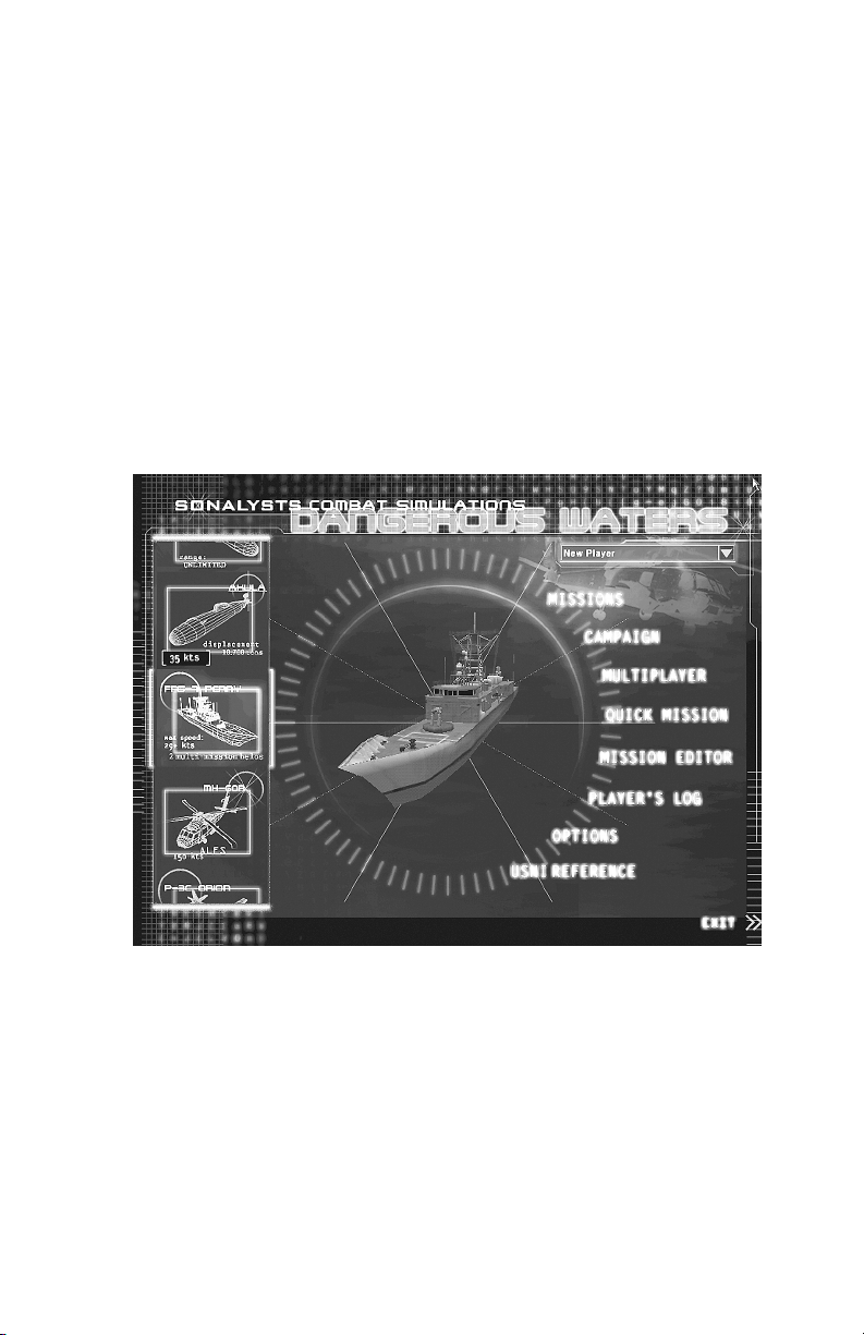
Choose Player
Name
Main Menu
CHOOSE PLAYER NAME
Following the opening video, the Main Menu appears. To skip the opening
video, press the spacebar.
Enter your player name in the Edit box at the upper right of the screen.
Previously created player names appear in the drop-down list. If you have
already created a name, click that name in the list. Your player “careers”
are automatically tracked by the game. See Main Menu/Player Log.
MISSIONS
Click Missions on the Main Menu to view the Missions screen. From here
Single or Saved missions are selected. The components of the Missions
screen are seen below.
Section 3: Main Menu
3-3
Page 32

Select Mission Type Platform Selection Window
Mission Title Selection Window
SELECTING A MISSION
The steps for selecting a Single or Saved mission are identical.
1. In the Missions screen click SINGLE or SAVED. Mission names of that
type appear in the Mission Title Selection Window. Stars preceding the
mission name denote level of difficulty, from one star (easy) to four
stars (most difficult).
2. Click the mission title of your choice. A description of the selected
mission appears in the Mission Description window. The tasking
overview for the default controllable platform appears in the Tasking
window. (Alternate tasking may be assigned to other controllable
platforms when they are available in a mission.)
3. Select an option from the Controllable Platform Selector drop-down.
The drop-down contains the list of Controllable Platforms available in
the selected mission. If the drop-down is greyed out, only one
controllable platform is available in the mission. See Platform Selection
Window below.
4. If the Specific Hull Selector is enabled (green) you can chose to
command any named submarine or FFG in the list. Otherwise the
platform shown is the only platform available in the mission.
5. To see another available mission, select a different mission title.
6. Click CANCEL to return to the Main Menu.
7. Click OK if you want to play the selected mission. The Mission Brief
screen appears and displays complete tasking information. You can
view or adjust the weapons loaded out for the selected platform in the
Section 3: Main Menu
3-4
Page 33

Weapon Loadout Screen accessed via the weapon icon button at the
bottom of the Mission Brief screen.
The Platform Selection Window
The Platform Selection Window contains a graphic of the selected or default
platform class and two drop-down lists. The upper drop-down list is the
Controllable Platform Selector. The lower drop-down list is the Specific Hull
Selector.
Country Indicator Selected Platform Graphic
Controllable Platform Selector Specific Hull Selector
All missions have at least one controllable platform. If the mission designer
has added more than one controllable platform to a mission each
controllable platform can be selected in the Controllable Platform Selector
drop-down.
Controllable Platform Selector
The mission designer decides which of the seven possible controllable
platform classes are controllable in a mission. In some missions the
designer permits some controllable platforms to offer the player a choice of
a specific named hull to command for the task. Asterisks, numbers and
color all indicate additional choices as described below.
Color implications: When the text and drop-down arrow are grey the
platform listed and shown in the graphic is the only type of controllable
platform in the mission. When the Controllable Platform Selector drop-down
arrow is green and the text is not greyed, additional controllable platforms
can be selected.
Asterisks: When an asterisk precedes the Controllable Platform Selector
option, additional options are available as described below:
*Controllable Surface: The Specific Hull Selector is enabled and
allows for the selection of any Oliver Hazard Perry class hull modeled
in the game.
*Controllable Sub: The Specific Hull Selector is enabled and allows
for the selection of any submarine hull regardless of sub class or
Section 3: Main Menu
3-5
Page 34

country. The tasking as written applies to whichever sub is selected,
regardless of country.
*Controllable Air: While it is possible to create a scenario with this
option (via the Player Has Choice of Platform option in the Mission
Editor) no numbered or named ‘hulls’ for aircraft exist in S.C.S. –
Dangerous Waters. Therefore only one option appears in the Specific
Hull Selector when an asterisk appears before Controllable Air.
Numbers: Numbers (#1, #2 etc) sometimes follow the text in the
Controllable Platform Selector.
A number following Controllable Air indicates either a) both types of
Controllable Air platforms have been added to the mission and can be
selected in the Controllable Platform Selector or b) two or more air
platforms of the same type have been added to the mission and can be
selected in the Controllable Platform Selector. Each will have a
different location and possibly different loadouts and/or tasking.
When a number follows Controllable Sub, more than one Sub can be
selected in the Controllable Platform Selector.
When a number follows the FFG more that one FFG can be selected in
the Controllable Platform Selector.
Note: Missions with more than one controllable platform can be
played as Multiplayer Missions. The number of controllable platforms
in a mission determines the number of players that can play that
mission. A number appears in front of Mission titles in the Multiplayer
Missions screen indicating the number of controllable platforms in
each mission. If the game session has been designated as a MultiStation multiplayer game, the number of Platforms appears before
the Mission Title. See the Multiplayer section of this manual.
Specific Hull Selector
The platform name that appears in the Specific Hull Selector when you click
OK is the platform you command in the mission. When the Specific Sub
Selector is enabled you can chose any platform hull in the list. The tasking
overview that appears in the Tasking Window applies to the platform
selected, even if the platform is from a different country.
Mission Brief
The Mission Brief Screen appears when you click OK in the Missions
Screen. The Mission Brief screen provides the complete tasking brief and
an opportunity to change your weapons loadout. This tasking is also
available during gameplay in the Task Bar’s Message History window
accessed by clicking the green square history button.
1. Click the Weapons Loadout icon button at the bottom of the Mission
Brief screen to review or alter your platform’s loadout to better suit your
mission needs. See Weapons Loadout below.
2. Click OK to begin the mission, or click CANCEL to return to the
Mission Selection screen.
Section 3: Main Menu
3-6
Page 35

Complete Mission Brief
Weapons Loadout Icon Button
Weapon Loadout
Depending on the mission tasking you may need to alter your default
weapons loadout. The Weapons Loadout screen is accessed via the
Weapons Loadout icon button in the Mission Brief screen. Here you can
change the weapons loaded in the tubes or the bomb bay or wing pylons,
change the number or type of stored weapons and sonobuoys, and adjust
the loadout of your countermeasures (CMs).
Note: The weapons available for each sub class vary. For instance
only one hull (Improved Kilo Hull # 368) of the Chinese Kilos can
carry the Klub Missile series. Only the weapons available on the
specific sub class appear in the drop-down-lists.
Section 3: Main Menu
3-7
Page 36

Launcher Location or Stores Information Window
Weapon Selection drop-down lists
To View or Change Default Loadout:
In the Mission Brief screen click the Weapons Loadout icon button at the
bottom of the screen. The Weapons Loadout screen appears with the
default (top) weapon location button selected in the upper left.
The buttons along the left side of the screen represent the location
of your controllable platform’s weapon and CM launchers or
pylons, and provide access to your stowed weapons,
countermeasures (CMs) and, when applicable, sonobuoys. These
buttons vary in number and name depending on the platform you
are commanding.
Click each button in turn to view or change the current loadout in
that location.
To Change Tube or Pylon Weapons, External CMs
1. Click a location button at the left side of the screen. Select the desired
weapon location. The loadout for a
represented by a numbered, colored circle or square on a wire frame
representation of the platform. Each number represents a specific
tube/pylon location. The name of the weapon loaded in each location is
seen in a drop-down list associated with each tube or pylon number.
The color of a circle or square on the wire frame coincides with the
color assigned to represent each specific weapon.
tube or pylon/bomb bay is
2. Click the arrow in a weapon drop-down list associated with a specific
location (tube, pylon, etc) and select a different weapon from the list to
change the weapon loaded in that location.
Note: Pylon # 12 on the P-3C in S.C.S. - Dangerous Waters is never
available for loadout. The ESM pod is carried there.
Section 3: Main Menu
3-8
Page 37

The P-3 Bomb Bay has four separate locations and each must be
loaded out individually. Select Bomb Bay in the left side button menu
then click one of the four semi-circles below the plane graphic to select
the loadout for that bomb bay location.
Bomb Bay locations
3. Click OK to implement all of your changes and return to the Mission
Brief screen.
4. Click CANCEL to ignore any changes you make on any of the
Weapons Loadout screens and return to the Mission Brief screen.
Rack Stowed Weapons, Sonobuoys, Munitions
In addition to weapons loaded in tubes or on other launchers, the subs and
the FFG carry a store of weapons to replace expended weapons and CMs
while underway. The controllable aircraft can carry extra sonobuoys and
CMs to load and launch from internal launchers while airborne. To
designate the number and type of items to be stowed, click the following
buttons in the Weapons Loadout screen:
Subs: Stores
FFG: Ship Stores, MK 13
P-3C: Sonobuoys, CMs
MH-60R: Sonobuoys, CMs
1. Click the desired button. A screen showing the type of weapons,
buoys, and/or countermeasures or other munitions that can be carried
on your platform is displayed. In some platforms the number of items of
Section 3: Main Menu
3-9
Page 38

a specific type currently loaded in tubes is visible along with the current
number of weapons of that type in the racks. While some platforms
show both tube and rack loaded items on the same Stores screen, only
rack stowed items can be changed here.
2. Click the right or left facing arrows associated with each item type to
increase or decrease the number of that item stowed.
The slash-separated numbers at the bottom of the Rack Stowed (or
Stowed) column, represent the number of items of that type currently
stowed followed by the total number of items of that type it is possible
to stow. For example if you are commanding a Seawolf class sub the
numbers 48/52 mean that there are currently 48 weapons stowed and
it is possible to stow 52.
In the Kilo, only tubes 5 and 6 allow for wire-guided weapons or the
UUV. These tubes have separate racks to accommodate wire-guided
items. Since the UUV must be wire-guided in order to return sensor
data, the UUV can only be added to Racks 5 or 6 in the Kilo.
In S.C.S. - Dangerous Waters sonobuoys descend to preset depths
designated “Deep” (400 feet) or “Shallow” (90 feet). You can select
sonobuoys of each preset type for your loadout. BT probes have no
depth preset.
Decrease the quantity of this item stowed
Item Type Increase the quantity of this item stowed
Total currently stowed / Maximum that can be stowed
3. Make the desired changes to all loadout screens before clicking OK.
Click OK to implement your changes and return to the Mission
Brief screen.
Click CANCEL to ignore any changes you made on any of the
screens and return to the Mission Brief screen.
Note: The changed loadout is attached to your player name and
becomes that platform’s default loadout for all subsequent missions
you play with the current player name until you change the loadout
again.
Section 3: Main Menu
3-10
Page 39

CAMPAIGN
Click Campaign in the Main Menu to access the Campaign Selection
screen. From here you select the campaign mission to play and the
platform to command in the mission.
RUSSIAN REBELLION
Struggling with their newfound democracy and being steered by elected
leadership that can ill afford new military initiatives, the Russian Navy is all
but forgotten. The crews and officers do their best to maintain their
cherished vessels but without the necessary resources their conditions
steadily deteriorate. Further, the Russian government is taking steps that
are increasingly authoritarian. In the Russian Far East, the military
responds by staging a mutiny of massive proportions. The Pacific Fleet in
Vladivostok and Petropavlovsk is seized by the newly formed Russian
Rebels. Moscow responds with the mobilization of the Northern fleet from
Murmansk to put down the rebellion and to regain control of the heart of
their Pacific Fleet forces and ports. U.S. intelligence gives an ominous
warning that ballistic missile submarines are among the captured assets
and cannot be found in recent satellite imagery. The U.S. immediately takes
the initiative in this matter of global security and deploys a naval task force
to the Sea of Okhotsk. However, Russian leadership maintains that the
insurgency is an internal matter subject to Russian sovereignty and warns
the U.S. that any direct involvement in the conflict will be considered an act
of aggression. The U.S. government disregards the warning and directs
Navy officials to proceed through International waters to the eastern shores
of Russia. The full mobilization of the U.S. and Russian navies in this
volatile region provides opportunities for rival countries to renew hostilities
and alter the established balance of power. The military forces of China,
Japan, India, and Taiwan are put on full alert as they brace for war.
The Russian Rebellion is portrayed by Moscow as a “lawless act by
desperate men resistant to change.” However U.S. surveillance and
reconnaissance soon discovers that this rebellion is not so easily explained.
Foreign merchant ships and naval vessels are detected moving covertly
amongst the Rebels and pre-planned alliances are indicated. Perhaps the
intentions of the Rebel forces are not as malevolent as they first appeared.
Russian leadership is consistently quiet when questioned by the U.S. and
maintains the threat that U.S. forces will be attacked if they interfere in what
the Russians insist is an internal conflict. Meanwhile, Chinese forces are
mobilizing. PLAN officials claim that the PRC is merely defending itself from
the potentially devastating and potent force of both Russian government
forces and rogue military assets controlled by the Rebels. However, the
sudden build-up of substantial Chinese forces in the Taiwan Strait
intimidates the Taiwanese and they initiate defensive war plans. The
eastern world is on the brink of war, and the outcome is perilously
uncertain.
Section 3: Main Menu
3-11
Page 40

CAMPAIGN ORGANIZATION
In S.C.S. – Dangerous Waters you have the choice to participate in the
campaign from multiple perspectives. You can control forces from the U.S.,
the Russian Loyalists, the Russian Rebels or the Chinese side, depending
on the mission tasking and objectives. Your decisions have an impact not
only on the direction of the conflict but may also dictate the alliances
between countries. Those alliances will remain persistent for multiple
missions or the entire campaign. However, in many instances the preexisting alliances will be decided dynamically from the start of the
campaign, and you must unravel the story behind the Russian conflict and
determine the true intentions of each side. Make the wrong decision and the
enemy forces you chose to destroy earlier in the campaign will no longer be
available to defend you once the true alliances are revealed.
To begin the Campaign:
1. From the Main Menu, click CAMPAIGN. The Campaign screen
appears.
2. In the upper Campaign Selection Window click the name of the
Campaign you wish to play: Mission names appear in the
Selection Window.
3. To view saved campaign missions click Saved Missions in the
Campaign Selection Window. A list of saved campaign missions
appears in the Mission Selection window.
4. Select the first (or next available) mission in the Mission Selection
window and read the description and tasking.
5. When you have the option to select a platform to play in a mission, the
text and down arrow seen in the Controllable Platform Selector is
green. Click the green arrow and select a different platform. Tasking for
the selected platform appears in the tasking window.
Mission
Note: To proceed to the next mission, you must successfully
complete all the current mission’s critical goals. Critical and noncritical goals are listed in the Mission Status screen during gameplay.
The Mission Status screen is accessible from the System Menu.
Press [ESC] or left click on the Nav Map to deselect any objects then
right-click on the Nav Map to access the Nav Map Menu then select
System Menu
6. Click OK to receive the Mission Briefing.
7. The Mission Brief screen appears listing your tasking and offering you
a chance to change your weapon loadout via the Weapons Loadout
icon button at the bottom of the screen.
8. Click OK to start the mission or click CANCEL to return to the
Campaign screen.
Section 3: Main Menu
3-12
Page 41

MULTIPLAYER
Up to thirty players can go head to head via Internet or a local network
connection. Create alliances and play against other alliances or the A.I.
Multi-Station mode permits you and other players to man stations within the
same platform and play as a team. For in-depth information, see Section 4:
Multiplayer in this manual.
QUICK MISSION
Quick Mission provides you the opportunity to create a dynamic mission
based on a few basic parameters that you select. Select any controllable
platform to command in the mission, a basic mission type, a level of
difficulty and general world location and quickly create a dynamic mission.
The type of mission depends on the platform you have chosen to
command.
TO PLAY A QUICK MISSION
In the Main Menu click Quick Mission.
1. From the Controllable Platform drop-down list select the platform you
want to command.
2. Click an available Mission Type option to select it.
3. From the Difficulty drop-down list select the desired level of difficulty
Easy, Medium, or Hard.
The number of enemy contacts and their capabilities determine
these levels of difficulty.
4. Click a Mission Location option to select a region of the world for the
mission.
5. Click OK to move to the Mission Brief screen.
6. Click the Weapon Loadout icon button and alter your weapons loadout
if necessary.
7. Click OK to return to the Mission Brief screen then click OK again to
start the mission.
REPLAYING A QUICK MISSION
If you find a Quick Mission that you really enjoyed playing you can play it
again or share it with your friends.
1. In Player’s Log click SINGLE to view Single missions. Quick Mission
results are included with Single Missions. Find and open the results for
the Quick Mission you just played. Quick missions do not have titles
but are identified by a seed number. (The most recently played mission
is located at the bottom of the list.) See Main Menu/Players Log for
information on how missions are retained in the Log.
Section 3: Main Menu
3-13
Page 42

2. Click on the Seed number of the desired mission and make note of the
seed number and all of the parameters (Controllable platform, Mission
type, Difficulty and Region.)
3. Return to the Main Menu then click Quick Mission.
4. Enter the seed number into the Seed field.
5. Select all the same parameters as were initially selected.
6. Click OK to access the Mission Brief then OK to start the mission.
MISSION EDITOR
The Mission Editor is a powerful tool for creating and editing missions. This
is the same tool used by the developers to create all missions in S.C.S. -
Dangerous Waters. The Mission Editor’s functionality is described in full in a
separate PDF file located on CD # 1 of your S.C.S. – Dangerous Waters
CDs in the Manual folder.
PLAYER’S LOG
S.C.S. – Dangerous Waters maintains a log for all player names you create.
The log allows you to access the debrief report of missions attempted by
the player name currently selected.
Missions are grouped by category represented by the text buttons at the left
of the screen: Campaign or Single.
Multiplayer and Quick Mission results are included with the Single
Missions.
The most recently played mission is found at the bottom of the list.
When a mission is played multiple times, the game saves a) the
highest scoring result for that mission and b) the results for the most
recently played mission (if not the highest). So, for a given mission, you
can have at most two entries in the log when that mission is played
more than once.
1. At the left of the screen click the desired text button to select the type
of missions you want to view. A list of all mission titles of that type
undertaken by your current player name is displayed. It may be
necessary to scroll down to see all mission titles.
2. Click a mission’s title to see the results of that mission. The information
displayed is the same as that displayed on the Mission Debrief screen
at the conclusion of that mission. Slightly different information appears
depending on the Mission Type.
3. Click BACK TO GAME LISTING at the bottom of the mission
information to return to the list of missions. You may need to scroll to
view this text.
4. Click OK or press [Esc] to return to the Main Menu.
Section 3: Main Menu
3-14
Page 43

OPTIONS
Selecting Options from the Main Menu displays the Options Menu. The text
buttons at the left of the screen make up the Options Menu and indicate the
type of options that are available. Click the name of the Options page you
wish to view. Some types of options have multiple pages.
Note: The options that are selected when you leave a game or
mission remain selected in subsequent missions until you change
them again.
GAME OPTIONS
On the Game page you set Game and Nav Map zoom and scroll options.
Some game options can be considered ‘cheats’, others set levels of
environmental reality. A check mark in the square preceding an option
indicates that option is ON or selected.
Show Dead Platforms: When ON, all platforms that are 100% damaged
display in their actual locations on the Nav Map and their actual identity is
displayed in the DDI and 3D View. Should the contact be killed by a
platform other than Ownship, the contact symbol displays on the Nav Map
whether you have detected it or not.
If you have detected the contact, the contact’s symbol remains on the map
moving at the course and speed designated in the TMA or reported solution
even after the actual ship or object is destroyed. This can result in seeing
two symbols and two 3D models for the same contact when this option is
on.
For example, assume you command a sub and have a contact designated
S01. You have a TMA solution on S01 that places it on bearing 235 at a
range of 4000 yards but the contact is actually on bearing 239 at a range of
5000 yards. Additionally, you have classified S01 as a Krivak class frigate
when it is actually a fishing boat. When you click S01 on the Nav Map the
3D model of a Krivak appears in 3D view.
Now suppose that you fire a torpedo at S01 using your TMA solution.
Because your solution is close to the actual location of the contact the
torpedo picks up the actual contact and destroys it. If you are attached to
the torpedo you will see it go right through your TMA solution in 3D because
it is not in the actual location of the contact. The torpedo proceeds on to the
actual location of the contact and kills it. A symbol for the contact
immediately appears at the actual location of the platform on the Nav Map
and the model of the dead fishing boat appears in the 3D View if you select
the symbol. Your S01 solution symbol and the Krivak model remain on the
map until you go to the TMA station, select S01 and drop it.
If Show Dead Platforms is OFF, you never see in 3D what you have killed.
Based on the sound of explosions and the loss of a signal on a given
bearing you may assume that you have killed something. If you want to
know for sure what you have killed without turning on this feature, go to the
Mission Status screen and scroll down to the Kills section.
Section 3: Main Menu
3-15
Page 44

Be aware that if your missile or torpedo does not produce 100% damage,
you will not see the wounded platform. You see explosion debris in 3D if
you are attached to the weapon symbol on the Nav Map. If you can see the
contact from the bridge binoculars, Gun Camera, the Sub periscope, the P3 or MH-60 Pilot’s station or the P-3’s IR Camera you will see the damaged
platform.
Show Truth: When ON, accurate NTDS symbols display for each object in
the mission on the Nav Map at the true location of the entity. When a
symbol is selected in Truth mode, the 3D object assigned to the class
appears in the 3D View and accurate information about the contact is seen
in the Data Display Indicator (DDI). When Show Truth is ON and a symbol
is selected on the Nav Map, the information in the DDI contains no solution
data and the actual name and class of the platform, its true course and
speed and its level of damage are displayed.
When Truth is ON, no Contact IDs are seen in the submarine’s Fire Control
drop-down lists. You can only engage Truth contacts from the Nav Map
using the Contact Menu’s Engage With command or by shooting a
Snapshot at the contact from a sub’s Fire Control Target Display. Truth
contacts can always be engaged by the FFG, P-3C and MH-60R.
Note: When Show Truth is ON and Show Link is OFF, no track
numbers appear on the Nav Map. When both Show Truth and Show
Link are ON, the four-digit numbers seen on the Nav Map do not
match the track numbers assigned by OS sensors or the Link that
are seen when only Show Link Data is ON. In the FFG if you assign
contacts to the Target Queue and then turn Truth ON, the targets in
the Queue are cleared. If you assign Truth track numbers to the
Target Queue then turn Show Truth OFF, the Target Queue is also
cleared. Any tracks that have been assigned to a launcher or tube in
one Truth mode are removed when you toggle the state of the Truth
mode.
Truth is OFF by default and must be enabled here or by using the keyboard
command or the Nav Map Menu. The default keyboard command is shown.
Press [Ctrl] + [Shift] + [T] to toggle the display of truth on the
Navigation Map.
From the Nav Map Menu, select Layers>Show Truth. Select
Layers>Hide Truth to turn truth OFF again.
Note: A host in a multiplayer game can turn OFF the Show Truth
capability so no players in the game can use it. See
Multiplayer/Multiplayer Options. In a Multi-Station game the host is
forced to set the truth mode for all players. Every player plays with
the same Truth setting. The Host can still toggle the Truth mode and
this toggles the Truth mode for all players regardless of side. The
host should not do this unless all players approve.
Show Allies: When ON, the true location of Ownside platforms appear at
their actual locations on the Nav Map. Accurate information appears in the
Section 3: Main Menu
3-16
Page 45

DDI when the contact is selected. The track numbers that appear for Allies
(your Link participants) are different when Show Allies is ON than they are
when Show Allies is OFF.
Show Link Data: When ON, friendly platforms appear on the Nav Map as
blue symbols of the correct platform type and class. The Link provides a
means for transmitting encrypted data between ships and/or aircraft on
Ownside.
When Show Link Data is ON in S.C.S. – Dangerous Waters the location of
all participants in the Link network as well as their contacts appear on the
Nav Map in the form of an NTDS contact symbol. See Navigation
Station/2D Navigation Map for further information on track numbers for Link
participants and their contacts.
Clicking on a Link contact symbol on the Nav Map displays information in
the DDI and the 3D view that is as accurate as the last report. The last
known position of the contact is represented on the 2D Nav. Link data are
reported on a time delay so the locations may not be exact but they are
locations with a high level of confidence. Link information is updated on the
Nav Map as long as the option is ON. When OFF the Link continues to
report but the updates are not seen until you turn the option back ON.
If the Show Link Data option is ON when you leave a mission, it is also ON
at the start of the next mission. Show Link Data is ON by default.
Note: Link submarines are not seen in your Link data unless they
are at comms depth with their radio mast extended. If you are
commanding a submarine, you must go to comms depth and deploy
the floating wire or raise the radio antenna to receive the Link data. If
you are commanding a sub, you will only see another sub in a
mission if that sub is at comms depth with his radio mast extended at
the same time you are at comms depth with your radio mast
extended.
From the Nav Map press [Shift] + [Ctrl] + [A] to toggle the display
of Link Data for allied platforms and land sites or select
Layers>Show Link Data (or Hide Link Data) from the Nav Map
Menu.
Note: Link contacts do not display in TMA drop-down lists. Some
land sites are designated during mission design as Auto Detect.
These show up on the Nav Map as Source: Link but with no specific
Link source designated.
Weapon Quick Launch: When ON, the time it takes to unload and load
submarine weapons and countermeasures and FFG torpedoes is reduced
as follows:
Weapon unload/load time drops from 16 – 18 minutes (depending on
the sub) to approximately 35 seconds.
Weapon load time drops from 8 – 9 minutes (depending on the sub) to
20 seconds.
Section 3: Main Menu
3-17
Page 46

Countermeasure unload/load time drops from nearly 6 minutes to 14
seconds.
Countermeasure load time drops from 3 minutes to 8 seconds.
FFG Torpedo reload time is reduced from 30 minutes to 30 seconds.
If Weapon Quick Launch is OFF at the time a weapon reload is started,
turning Quick Launch ON will not alter the reload time of the currently
loading weapon. All subsequently launched weapons will load and Launch
using Quick Launch times.
Aircraft Quick Launch: When ON, launch-time units are measured in
seconds instead of minutes. The time to launch the helo from the FFG
hangar is one hour. 30 minutes to get to Alert 30, another fifteen minutes to
get to Alert 15, ten minutes to get to Alert 5 and five minutes to get to
launch time. Enabling Aircraft Quick Launch reduces this time from 60
minutes to 60 seconds. Aircraft Quick Launch applies to the FFG’s Helo
and any other A.I. aircraft in the mission.
If Aircraft Quick Launch is OFF at the time an aircraft launch is ordered,
turning Aircraft Quick Launch ON will not alter the launch time of the
currently launching aircraft. All subsequently launched Aircraft will load
using Quick Launch times.
Quick Damage Repair: When ON, the time required to repair damaged
equipment is measured in seconds rather than minutes. Items that cannot
be repaired are not affected by this option. If a repair has started with Quick
Repair OFF, turning Quick Repair ON will not hasten the repair time of the
current system. Subsequent damage will be repaired quickly.
Enable Tool Tips: When ON the name of the screen, button name or
function and in some cases additional information displays when the cursor
is held over game labels, buttons and entry fields.
Enable Wind: The mission designer determines if wind regions are defined
in a mission. This option cannot be changed once a mission has started.
When Enable Wind is ON, wind affects Ownship navigation. Crosswinds
push your aircraft or FFG Ownship off course. Opposing winds slow your
Ownship and trailing winds speed it up. If you order an exact speed via the
Task Bar, your crew takes wind into account in maintaining your ordered
speed. Note that the speed readout on the Task Bar shows forward speed
through air or water, not speed over the ground. If you've ordered an exact
speed, the indicated speed may be higher if you're heading into a wind, or
lower if you have a trailing wind. Wind speed and direction are noted in the
aircraft and FFG Task Bar. Novice players may wish to turn this option OFF
Enable Currents: The mission designer determines if water regions
(currents) are defined in a mission. This option cannot be changed once a
mission has started. Any water region defined for a mission by the mission
designer produces water currents that affect navigation when Ownship is a
sub or the FFG. Crosscurrents can push your ship off course. Heading
directly into a current slows your ship, while moving with the currents
increases your speed. If you order an exact speed via the Task Bar, the
crew takes currents into account in maintaining your ordered speed, but if
Section 3: Main Menu
3-18
Page 47

you give a specific engine order, your actual speed may vary. Note that the
speed readout on the Task Bar shows forward speed through water, not
speed over the ground. If you've ordered an exact speed, your indicated
speed may be higher if you are driving into a current, or lower if you are
riding with a trailing current. There is no way to determine the direction of
currents. Novice players may wish to turn this option OFF.
Enable Waveriding: When ON, the 3D platforms ride the waves
realistically based on the sea state set when the mission was created.
When OFF, objects in the water in a high sea state will not follow waves,
but will stay straight and level. This may cause models to submerge or float
above the waves in 3D. This option should only be disabled to lighten CPU
load for performance reasons.
3D OPTIONS
These two pages of options allow for setting screen resolution, 3D effects
and testing options. Changes you make can be viewed in the 3D Window.
The following two items bear additional explanation.
Select
Select
Tip: If you experience banding or pixilated graphics in your 3D view, try
turning off any anti-aliasing settings you may have adjusted in the DirectX
panel on your computer.
Disable 3D on the second page of options to completely
disable 3D in a mission. The Host in a multiplayer game can
choose to disable 3D for all players or allow them to make their
own choice. See Multiplayer/Multiplayer Options.
Windowed to run S.C.S. – Dangerous Waters in a smaller
window. This is especially useful when reading on-line
documentation.
CREW OPTIONS
Each controllable platform has several Autocrew options. Each can be
tuned on or off before game start at the option screen. During gameplay,
use the Autocrew slider button, in the upper left of any station that has an
Autocrew, to toggle the state of that Autocrew without returning to the
Options screen. You can also access the Options screen from the System
Menu during gameplay by pressing [Esc] (default hot key.)
Clicking Defaults (Novice) turns ON all Autocrew options.
Clicking Defaults (Advanced) turns OFF all Autocrew options.
Each type of platform has a unique set of Autocrew pages. Click the desired
platform type at the top of the screen to access that platform’s options.
When ON (check-marked) Autocrew perform specific game tasks as
follows:
Sub
Use Radar Autocrew: When ON, Radar Autocrew marks and updates
all Radar contacts as long as the Radar is on.
Section 3: Main Menu
3-19
Page 48

Use TMA Autocrew: When ON, TMA Autocrew merges contacts,
performs TMA assessment, and enters Firing Solutions for all
designated contacts.
Note: When the TMA Autocrew is ON you cannot move the ruler or
enter data into the trial solution fields.
Use Sonar Broadband/Narrowband Autocrew: When ON, the Sonar
Autocrew marks contacts in Narrowband sonar and assigns trackers.
(Trackers appear in both Narrowband and Broadband displays) He
then commences classifying the contact in Narrowband. Once
classified, the contact’s symbol on the Nav Map changes shape to
reflect the classification determined by the Broadband/Narrowband
Sonar Autocrew. You must still assign an alliance ID to the contact
from the Contact Menu’s Designate Category/ID> ID option. See
Navigation Station/2D Navigation Map/Contact Menu.
Note: When Broadband/Narrowband Sonar Autocrew is ON you can
still assign trackers and mark contacts. In some cases you may be
quicker than he is. You can also move the Narrowband Cursor to
designate the area for the Autocrew to search.
Use Sonar Active Intercept Autocrew: When ON the Autocrew
marks all contacts detected in Active Intercept.
Use Fire Control Autocrew: When ON, the Fire Control Autocrew
enters presets appropriate for the contact. The contact must be
categorized (surface or subsurface) and have a firing solution, not just
a line of bearing, before it can be assigned to a tube. Autocrew does
not assign contacts to a tube.
Note: Be aware that if you classify a contact as a surface ship when
it is really a submarine, the Fire Control Autocrew enters presets
appropriate for a surface ship. He uses your classification and the
existing TMA firing solution to determine appropriate presets, even if
your classification and firing solution are wrong.
Air
Use Acoustic Autocrew: When ON, Acoustic Autocrew switches
between channels, clears channels as needed to support Directional
mode, and places buoys in Directional mode. Acoustic Autocrew does
not place buoys in Active mode. In Directional mode he marks and
classifies contacts.
Use ESM Autocrew: When ON, Autocrew marks ESM contacts but
does not classify them. (MAD contacts are marked automatically when
the MAD sensor is ON. While MAD shares the station with ESM, it is
not tied to the ESM Autocrew.)
Use Radar Autocrew: When ON, Radar Autocrew marks contacts and
sends position updates to the Nav Map as long as the Radar is ON.
Section 3: Main Menu
3-20
Page 49

Use TACCO Autocrew: When ON, TACCO Autocrew enters torpedo
presets appropriate for the selected contact. You must select the
contact and the weapon to be dropped or launched. You cannot enter
torpedo presets when the Autocrew is on.
Use Countermeasure Autocrew: When ON, the Countermeasure
Autocrew takes evasive maneuvers and launches chaff and flares
when a missile is locked on your Ownship aircraft.
Helo
Use ATO Autocrew: When ON, ATO Autocrew enters Penguin missile
and torpedo presets appropriate for the contact. You must select the
weapon to be dropped or launched. You cannot enter presets other
than runout bearing when the Autocrew is on.
Use SENSO Acoustic Autocrew: When ON, Acoustic Autocrew
switches between sonobuoys, places buoys in Directional mode, and
clears channels as needed to support Directional mode. Acoustic
Autocrew does not place buoys in Active mode.
Use SENSO Dipping Sonar: When ON, Autocrew marks contacts in
Passive Mode. Autocrew does not mark Active contacts nor classify
contacts in passive mode.
Use SENSO ESM Autocrew: When ON Autocrew marks ESM
contacts but does not classify them. (MAD contacts are marked
automatically when the MAD sensor is ON. While MAD shares the
station with ESM, it is not tied to the ESM Autocrew.)
Use SENSO Radar Autocrew: When ON, Radar Autocrew marks
contacts and sends position updates to the Nav Map as long as the
Radar is on.
Use Countermeasure Autocrew: When ON, the Countermeasure
Autocrew takes evasive maneuvers and launches chaff and flares
when a missile is locked on your Ownship aircraft.
Surface
Use Acoustic Autocrew: When ON, Acoustic Autocrew switches
between hot sonobuoys, places buoys in Directional mode in Gram
windows A - D (see note below), clears channels as needed to support
Directional mode and marks and classifies Directional contacts.
Acoustic Autocrew does not place buoys in Active mode, classify
contacts in Omni mode or switch receiver modes (Ship, Air or Air/Ship
modes.)
Note: On the FFG, only display windows (gram displays) A – D can
be set to Active or Directional Mode. If your helo is not aloft and you
or your Acoustic Autocrew want to mark Directional contacts, the
player must set the Receiver mode to SHIP/SHIP. To view Helo
sonobuoy data in Gram windows A – D you must SYNC with the
Helo in ASTAC and set Link mode to ACOUSTIC and display
windows A – D must be set to AIR/SHIP.
Section 3: Main Menu
3-21
Page 50

Use EW Autocrew: When ON EW Autocrew marks contacts. He does
not apply classes or classify the contacts.
Use Towed Array Autocrew: When ON the Towed Array Autocrew
marks contacts, assigns ATF (trackers), and resolves ambiguous
contacts.
Use TMA Autocrew: When ON, the FFG’s TMA Autocrew merges
contacts, performs TMA assessment, and enters Firing Solutions for all
designated contacts. When ON, the TMA Autocrew also tears the page
when the OS indicator light reaches the edge of the page.
Note: Be aware that zooming in the range when the OS indicator is
close to but not yet at the edge of the page will cause the Autocrew
to tear off the page and lose the lines that were there.
Use Torpedo Control Autocrew: When ON Autocrew enters presets
appropriate for the selected target.
Use Countermeasure Autocrew: When ON the Autocrew launches
chaff and flares when incoming missiles are detected.
SOUND OPTIONS
From the Sound options page you can enable voice commands as well as
in-game sound and music options. A list of available English voice
commands is found in VoiceCommands.doc located on both of the S.C.S. –
Dangerous Waters CDs in the Manual directory.
Enabled Only: This option is used in conjunction with Voice
Commands. When Enabled Only is ON and the designated speech key
is pressed during gameplay, voice recognition is listening and the
speech engine interprets anything you say. When this key is released,
voice recognition is not listening and it ignores anything you say
Press and hold the speech key while issuing a valid voice
commands. By default the speech key is [W].
Always On: This option is used in conjunction Voice Commands.
When Always On is selected, the designated speech key is ignored
and the speech engine is always listening to what you say.
Issue a valid voice command as desired at any point during
gameplay.
Page 2 of Sound Options:
Status Messages: This area reports any sound initialization errors
indicating if the sound engine was successfully initialized and how
many buffers were created. If you are having sound or sound card
issues, check this page for additional information.
Enable Special Effects: This option is enabled only if the current
machine supports this capability. When enabled effects such as reverb,
audio level adjustment and other effects are applied to the sound
during the game. The Special Effects option is used to mute the
Section 3: Main Menu
3-22
Page 51

volume of the 3D sound when inside the FFG Bridge and other areas in
the game.
CONTROLS OPTIONS
The Controls pages display the current hot key assignments for the Sub,
Surface, and Air platforms as well as 2D Map, 3D View and General game
functions. This manual assumes the default key assignments are in effect
but you can change key assignments as desired.
Explanation of Controls
While most of the keyboard hot-key options are fairly self-explanatory a few
require further explanation. These are covered below:
General Controls: These are controls that are not specific to the Nav Map
or any specific controllable platform.
“Escape” Menu: System Menu. [Esc] is the default hot key. The
manual refers to this menu as the System Menu in all places.
Mission Status: Mission Status screen provides information about the
current game during gameplay (player name, controllable platforms,
current status of goal completion.). Mission Status is accessed via the
System Menu during gameplay.
Keyboard Course/Speed /Depth or Altitude Change: These options
provide a means for entering an exact number in the Task Bar’s
Course, Speed, and Depth (Alt) fields rather than clicking on the digits.
Press the keyboard combination for the desired option. When the digits
in that field change color quickly enter the desired digits via the
keyboard.
Map Controls: These options control Navigation Map functionality.
Hide/Show Entity Truth: Shows the true identity and location for all
platforms in the game. See Options>Game>Show Truth
Terminate Action: This refers to canceling the creation of a Map
Object (such as a navigation mark, range circle, or waypoint insertion)
prior to the placement of the object. When one of those options is
selected the cursor changes shape until the action is completed.
Terminate Action causes the cursor to return to normal.
Add Manual Solution: A manual solution places a yellow NTDS
Symbol indicating an Unknown Category/Unknown ID on the Map at
the location of the cursor. For more information on how to use a
Manual Contact see Navigation Station/2D Navigation Map/Nav Map
Menu/Add Manual Solution.
Promote to Link: Select this option to provide the link participants with
your position report and assessment of the selected contact. This is
most useful in Multiplayer games although you may want to use it in
single player games if you want the Link participants to attack a contact
you designate as hostile. See Navigation Station/2D Navigation
Map/Contact Menu/Promoting a Contact to Link.
3D Options: These controls refer to the 3D view on the Navigation Station.
Section 3: Main Menu
3-23
Page 52

Toggle Cinematic Camera: When this option is activated it jumps the
3D view to wherever the ‘action’ is (a missile launch, missile hit etc.)
Changing Hot Key Assignments
To change hot key assignments from the Options>Controls pages:
1. Double-click the text of the option you want to change. The option is
highlighted and the text changes color.
2. Press the desired new key or key combination. An alert message
appears if that key or key combination is already assigned to another
command and displays the name of the command currently assigned
the key(s) you pressed.
3. Click YES to swap the two key assignments. Click NO to maintain the
current hot key settings.
4. Click OK at the bottom of the Options Menu to accept all changes.
Click CANCEL to ignore all changes and retain your original settings.
Program Joystick to fly P-3C and MH-60R
1. Ensure that the joystick is attached to the computer according to the
joystick instructions.
2. From the Controls page click AIR/HELO to select it. A check mark
indicates the option is selected.
3. Double click a line option in the list then move the joystick control as
desired to associate that movement with the selected option. Items with
no hot key assignment are options that relate to a Joystick only.
4. Continue until all listed options have been associated with a
movement.
MULTIPLAYER OPTIONS
Multiplayer options are only available to the host in a multiplayer game
during the setup for a multiplayer game. Options you set here are enabled
when you host a Multiplayer game. If you join a Multiplayer game any
options you set here are disabled. When you host you can also set these
options from the Gameroom. Multiplayer Options are explained in full in the
Multiplayer section of this manual. See Multiplayer/Multiplayer Options.
SAVING OPTION CHANGES
To save options changes: Click OK to apply all changes made on any
page. The Options Menu closes.
To exit the Options Menu without enabling any changes: Click
CANCEL. The Options Menu closes.
RESTORING DEFAULT SETTINGS
Default settings can be restored by option type. (Game, 3D, Crew, Sound,
Controls and Multiplayer.)
Section 3: Main Menu
3-24
Page 53

Select the desired type of option then click Defaults at the bottom
of the page to set that type of options to the default settings
shipped with the game. Each option type has a separate Defaults
button. Some Options have Novice and Advanced Settings. See
Novice and Advanced Defaults below.
There are six pages of Controls options. (General, Map, 3D, Sub, Air/Helo,
Surface) The defaults can be restored to each page individually. Likewise,
the multiple pages of Crew options can be set by individual platform. Crew
Options defaults have both Novice or Advanced settings. See below.
NOVICE AND ADVANCED DEFAULTS
The first time you run S.C.S. – Dangerous Waters you will notice that some
Game and Crew options are turned on or off at game startup depending on
whether you selected Novice or Advanced settings during game installation.
To switch from one setting to the other or to restore the original
settings if you have altered them select Defaults (Novice) or
Defaults (Advanced) as desired from each page that contains
those options.
If a page has only one Defaults button, the default options are the same for
both novice and advanced players.
Note: This manual assumes Advanced CREW options and Novice
GAME options are selected. If you have selected other Options
settings, your game experience will be slightly different than
described in this manual.
Advanced Defaults
Game options: Turns ON Show Link Data, Enable Tool Tips,
Enable Wind, Enable Currents, and Enable Waveriding. All other
Game options are OFF.
Crew options: Turns OFF all Autocrew.
Novice Defaults
Game options: Turns ON Show Dead Platforms, Show Link Data,
Weapon Quick Launch, Aircraft Quick Launch, Quick Damage
Repair, Enable Tool Tips and Enable Waveriding. All other Game
options are OFF.
Crew Options: Turns ON all Autocrew options.
USNI REFERENCE
Data from the U.S. Naval Institute (USNI) was used as the source for the
information in the in-game USNI Reference browser, and for the
performance parameters used in the game databases. Any deviations from
USNI data for gameplay purposes are noted in the browser entries.
Section 3: Main Menu
3-25
Page 54

USING THE BROWSER
To access Reference Information from the Main Menu:
1. Click USNI REFERENCE on the Main Menu. The Information Browser
opens.
2. Click the desired country and platform name or the desired weapon
type and the weapon name about which you want to learn more. The
browser shows the text entry by default.
3. Click TEXT, PHOTO or 3D at the left to view the designated type of
entry.
4. Press the right and left arrow keys to page through the text, photo or
3D entries of a given type for the selected country or weapon type
5. Click the house (home) icon to return to the table of contents.
6. Click OK to return to the Main Menu.
To manipulate the 3D object in the browser:
Press the spacebar or any arrow key to stop the rotation of the 3D
object.
Press [S] to start the object rotating again.
[Ctrl] + Click and drag or right-click and drag: Zooms in/out on the
selected object.
[Ctrl] + Arrow Keys or click and drag: Rotates the camera above, under
and around the object.
Select Country or Weapon Type Select specific platform or weapon
Show Table of Contents Close Browser
Section 3: Main Menu
3-26
Page 55

To display the browser from any screen during gameplay:
Press [Esc] to access the System Menu or click the Nav Map the
right-click to display the Nav Menu and select System Menu from
the Nav Map Menu. Select USNI Reference.
Click OK to close the browser and return to the game.
PLATFORM-SPECIFIC INFORMATION
You can quickly access information on a selected contact in the game or in
the Mission Editor.
During Gameplay:
Select the contact on the Nav Map then press [Alt] + [I].
The USNI Browser opens to the entry for the selected platform. Be aware
that the browser provides information on the platform as classified by you. If
you select a contact you have classified as a Kirov, the browser entry for
Kirov is displayed, even if the contact is really a Slava.
Note: If Show Truth is ON, the browser displays the correct entry for
a selected contact.
Click OK to return to the game.
In Mission Editor:
Assign a country, class and name to the platform. Select the icon
on the map and press [Alt] + [I]. The browser opens to information
on the selected platform.
Click OK to return to the Mission Editor.
Note: No USNI information is available for land buildings, civilian
aircraft and sailing vessels. During gameplay and in the Mission
Editor, the browser’s Main Menu displays if you attempt to access
platform-specific information about a contact that has no browser
entry.
EXIT
To exit the Main Menu:
Click EXIT. An S.C.S. - Dangerous Waters message box appears
asking you to confirm that you want to leave the game.
Click OK to exit to Windows.
Click CANCEL to return to the Main Menu.
Tip: Press the spacebar or click the screen to bypass the credits.
Section 3: Main Menu
3-27
Page 56

Section 3: Main Menu
3-28
Page 57

SECTION 4
MULTIPLAYER
Section 4: Multiplayer
4-1
Page 58

4: MULTIPLAYER ........................................................................................4-3
TO HOST A MULTIPLAYER GAME ...........................................................4-3
Gameroom (Multiplayer Host Options).................... 4-3
TO JOIN A MULTIPLAYER GAM E ............................................................4-4
LOBBY............................................................................ 4-5
GAMEROOM (MULTIPLAYER JOIN OPTIONS) .......................4-6
MULTI-STATION MODE .........................................................................4-7
MULTI-STATION MODE (HOST OPTIONS)............................ 4-7
MULTI-STATION MODE (JOIN OPTIONS) ............................. 4-9
MULTIPLAYER OPTIONS ..................................................................... 4-10
MULTIPLAYER DEFAULT SETTINGS ..................................4-12
To set Novice Settings:......................................... 4-12
To set Advanced Defaults:....................................4-12
CHAT.............................................................................................. 4-12
GAMEPLAY DIFFERENCES IN MULTI PLAYER ........................................... 4-13
PROMOTING CONTACTS TO THE LINK ............................... 4-14
To Promote a Contact to the Link .........................4-14
MH-60R MULTIPLAYER GAMEPLAY DIFFERENCES............4-14
FFG MULTIPLAYER GAMEPLAY DIFFERENCES.................. 4-15
ASTAC Station Differences...................................4-15
Navigation Station Difference ............................... 4-16
Weapons Coordinator/Target Queue .................... 4-16
SUBMARINE MULTIPLAYER GAMEPLAY DIFFERENCES ........4-16
MULTI-STATION DIFFERENCES ........................................4-17
MULTIPLAYER WARNING AND ERROR MESSAGES ................................. 4-17
Section 4: Multiplayer
4-2
Page 59

4: MULTIPLAYER
S.C.S. - Dangerous Waters allows you to host or join multiplayer games on
a local area network or over the Internet. New in S.C.S. – Dangerous
Waters is Multi-Station mode. In a Multi-station game a team of players are
assigned stations on a single platform each taking one or several stations to
man as desired.
A multi-manned platform can play against the AI (Artificial Intelligence) or
against other multi-manned platforms in a multiplayer Multi-Station game.
See Multiplayer/Multi-Station Mode for instructions on setting up a
multiplayer game in Multi-Station mode.
TO HOST A MULTIPLAYER GAME
As Host you select the mission, players and options available to all players.
You decide if the session is a regular Multiplayer game or a Multi-Station
game by selecting (or deselecting) the
the bottom of the Configuration screen. See Multiplayer/Multi-Station Mode
later in this section. Multiplayer mode is covered here.
1. From the Main Menu, click MULTIPLAYER to reach the Multiplayer
CONFIGURATION screen
2. Click HOST. Host options appear on the Multiplayer Configuration
screen.
3. Enter a name for your game in Session Name.
4. If desired, click the appropriate check-box to select either or both of the
following. A checkmark indicates the item is selected.
Select Require Password to Connect then enter a password in
the Password field.
Select
Tip: Be sure to share the password with fellow players prior to starting the
mission.
Host Multi-Station game to make platform station
selection available in this session. See Multiplayer/Multi-Station
Mode later in this section.
Host Multi-Station game option at
5. Click OK to enter the CONNECTIONS screen.
6. Click the desired connection mode to select it.
7. Click OK to enter the GAMEROOM.
Gameroom (Multiplayer Host Options)
As players join the game their names appear in the Name column of the
Gameroom. (Host options for Multi-Station Mode are covered later in this
chapter. See Multiplayer/Multi-Station Mode (Host Options).)
Section 4: Multiplayer
4-3
Page 60

1. Click MISSION SELECTION to display the Multiplayer Missions
screen. (All Single missions with more than one controllable platform
are available to play in the Multiplayer Missions Screen).
2. Select a mission from the list of titles. The number of possible
PLAYERS in a mission is shown before the mission title. The number
of stars indicates the level of difficulty of the mission.
3. Select a platform to command from the Controllable Platform Selector
and Specific Hull Selector list. While a platform appears by default, that
is not your selected platform until you select it. For more information on
platform selection and the Controllable Platform Selector and Hull
Selector see Main Menu/Missions.
4. Click OK to apply your selections and return to the Gameroom.
5. Brief and Weapon Loadout buttons are now selectable and the name of
the submarine you selected appears in the Platform column following
your player name.
Click
Click WEAPON LOADOUT to adjust your platform’s loadout based
BRIEF to read the tasking for this mission.
on the tasking.
6. The Host determines which options are allowed in a multiplayer game.
Click OPTIONS to set the options that are available to all players
in this multiplayer game. See Multiplayer/Multiplayer Options later
in the chapter.
Click OK to apply your selections and return to the Game Room.
Click CANCEL to return to the Game Room without changing any
Options.
7. When all desired players have joined and indicate they are ready to
start, click PLAY.
8. To deny game access to a specific player, select the player’s name
then click REFUSE PLAYER.
TO JOIN A MULTIPLAYER GAME
This section covers joining a multiplayer game. Steps for joining a MultiStation game appear later in this chapter. See Multiplayer/Multi-Station
Mode/Multi-Station (Join Options).
1. From the Main Menu, click MULTIPLAYER to reach the Multiplayer
screen.
2. In the CONFIGURATIONS screen click OK to search for all open
sessions. If you know it, enter a specific Host name or IP address in
the edit field to access the game hosted by that computer. Click OK.
The CONNECTIONS screen appears.
3. Click the desired type of connection to select it then click OK to enter
the Lobby.
Section 4: Multiplayer
4-4
Page 61

LOBBY
The Lobby screen is divided into three sections or windows:
The
SESSION window displays the names of any hosted sessions. The
highlighted name is the selected session.
The letters MS appear after the Session Name when the session is a
Multi-Station game.
The letter Y appears after a session name under the padlock icon if a
password is required to join the selected session. An
no password is required.
Player/Max: The number of players currently connected is followed by
the total number of connections supported by S.C.S. – Dangerous
Waters.
The Ping rate to the host is shown in the PING column.
The
PLAYERS window displays the names of those players connected to
the selected session.
MISSION DESCRIPTION window displays a description of the mission
The
if the selected Session Host has selected a mission.
1. Click the name of the game session you want to join.
2. Click OK to enter the Gameroom.
If you do not have the selected scenario or have a different version
of the scenario the host computer notifies you and offers to send it
to you. Click
enter the Gameroom. If you click CANCEL in this message box
you enter the Gameroom but the only available option is Cancel.
OK in the message box to transfer the scenario and
N indicates that
Note: The scenario transferred by the Host is sent to your Incoming
directory. The incoming file does not overwrite a mission by the
same name that exists in your Scenario directory. If the Host
changes the mission and sends it again, this new (changed) file will
overwrite the version in the Incoming directory.
Section 4: Multiplayer
4-5
Page 62

Join Hosted Session Names Session is a Multi-Station Game (MS)
Password required (Y/N)
Connected Players
GAMEROOM (MULTIPLAYER JOIN OPTIONS)
Once the Host has selected a mission, the options at the left of the
Gameroom screen are selectable.
Note: If the host has not selected a scenario before you enter the
Gameroom and subsequently selects a mission that you don’t have
or that is different from your version, you are notified via an error
message that the host can send you the scenario. Click OK to
continue. This scenario is placed in the Incoming directory, not in the
Scenario directory.
1. Click PLATFORM SELECTION to select a platform to command in the
mission. The Multiplayer Missions screen appears showing the name
of the selected mission. The number of stars at the beginning of a row
indicates the level of mission difficulty. (One star is easiest, four stars is
most difficult). The number of possible players in the mission precedes
the name of the mission.
2. From the Controllable Platform Selector dropdown list in the upper
right, select a controllable platform. Platforms selected by other players
are unavailable and list a player’s name in parentheses.
3. When you have made your selection click OK to return to the
Gameroom.
4. Click OPTIONS to select or view the Multiplayer options allowed by the
Host. Set any allowable options in the Game, Crew or 3D Options
pages as desired.
Section 4: Multiplayer
4-6
Page 63

Be aware that the host controls which options may be set, must be
set or cannot be set. If the host disallows Show Truth, you will not
be able to see truth even if you have Show Truth enabled in your
game options. See Multiplayer/Multiplayer Options later in this
section.
5. Click BRIEF to read the tasking for this mission.
6. Once you have selected a platform to command click WEAPON
LOADOUT
Click
to adjust your platform’s weapons loadout.
OK in the Weapon Loadout screen to accept any changes
you want to implement. Click
made.
CANCEL to negate any changes you
7. Click READY to notify the host you are ready to play. If you need to un-
ready to adjust your loadout, click READY again to return to the
Gameroom. Clicking Cancel takes you back to the Lobby.
MULTI-STATION MODE
In Multiplayer Multi-Station mode two or more players can man different
stations on the same platform and play against platforms manned by the AI
or other teams of players manning a single platform. Each player assigned
to a single platform is responsible for one or more stations as assigned or
selected. If for example, FFG Player 1 is assigned the Towed Array Station
on the FFG, FFG Player 2 cannot access the Towed Array Station and
cannot use voice, keyboard or right-click menus to access the Towed Array
station or make any changes there. Player 2 has access only to his own
assigned stations.
Players assigned to the same platform should agree on station assignments
although it is possible for any player on a given platform to unassign and
reassign stations to other platform members. Any player assigned to a
platform can adjust the Weapons Loadout.
Note: If a player in a Multi-Station game drops out, his stations
remain unmanned.
MULTI-STATION MODE (HOST O PTIONS)
The Host in a multiplayer game decides if the mission is to be played in
Multi-Station mode. The host is forced to decide if all players play with Truth
on or OFF. Players do not have a choice and the host must pick one mode
or the other.
1. In the Main Menu, select MULTIPLAYER.
2. The CONFIGURATION screen appears. Enter a Session Name. If
desired, indicate if a password is required to join and enter the
password.
Section 4: Multiplayer
4-7
Page 64

3. Click the square in front of Host Multi-Station game if no check mark
is visible there. When a check mark appears in front of the Multi-Station
option, click
OK.
4. Select a connection type from the CONNECTIONS screen then click
OK.
5. The Gameroom appears. Click MISSION SELECTION to access the
Mission Menu and Controllable Platform Selector.
6. The Mission Menu now lists mission titles as before but the number of
Platforms in a mission now appears instead of the number of Players.
Select a mission and a platform from the Controllable Platform
Selector. Click
Each platform in the mission can be selected as a Multi-station
platform. In a mission with 4 platforms, each of the platforms can
be played in Multi-Station mode so only the number of platforms
and stations on those platforms limits the number of players.
OK to return to the Gameroom.
7. Click ASSIGN STATIONS. IN the Stations dialog that appears, click
your player name to select it if it is not already selected. Click the name
of a station on the right then click the left facing arrow in the center of
the dialog to assign that station to the selected name. Select as many
stations as desired or as agreed upon with fellow team members. Click
OK.
Other players manning the same platform can access that
platform’s ASSIGN STATION dialog one at a time. Click
following your selection to free the dialog for other players to select
stations.
A message appears informing you which stations are currently
unassigned. All stations must be assigned before game start.
OK
Note: If a player manning stations on your platform drops out of the
game, his stations are not accessible. Functions performed at that
station can no longer be performed.
8. Click OPTIONS then Multi-player Options to set options that are
available to or forced upon other players. See Multiplayer/Multiplayer
Options.
Because track numbers differ when Show Truth is ON, all players in a
Multi-Station game are forced to play with the same Truth setting to
avoid confusion. The host determines if Truth is ON or OFF for all
players.
Note: In Multi-Station mode it is important not to force the player to
have Autocrew ON. The player could be left with nothing to do at his
station since some Autocrew functions lock out any player interaction
at the station. It is recommended that you force the players to have
all Autocrew Options OFF for Multi-Station games or leave him with
the possibility of turning Autocrew ON or OFF as desired.
Section 4: Multiplayer
4-8
Page 65

9. To deny game access to a specific player, select the player name and
click
REFUSE PLAYER.
10. When all players have clicked READY, click PLAY.
Note: You are prevented from starting a Multi-Station mission until
each station on every platform is assigned. The Host is notified of
unassigned stations on any platform when he clicks PLAY. The Host
must then notify players via chat to assign all stations on the
indicated platform(s). The Host cannot assign stations to platforms
other than his own.
MULTI-STATION MODE (JOIN O PTIONS)
There is no way to tell if a game is a Multi-Station game from the Lobby or
when you initially enter the Gameroom. Multi-Station games are identifiable
from the Mission Selection screen. In Multi-Station mode the number of
Platforms is listed in the column in front of the mission name instead of the
number of Players. Additionally a platform already selected by one player is
still selectable by other players. No player names are attached to a
platform.
1. Select a Host in the Lobby.
2. In the Gameroom, notice which players are currently assigned to a
specific platform if you want to team with specific players. Click
MISSION SELECTION.
To join a platform as part of that platform’s team, select the
desired platform name in the Controllable Platform Selector.
If other controllable platforms are available in the mission, select a
different platform and wait for other players to join your platform’s
team. If no one else joins your team you must assign all stations to
yourself.
3. Click OK to apply your platform selection and return to the Gameroom.
4. Click ASSIGN STATIONS. Ensure that your player name is selected in
the Stations dialog. Select a station name on the right then click the
left-facing arrow in the center of the dialog to assign that station to
yourself. Select as few or as many stations as agreed upon with your
teammates. Click
the Gameroom.
If another member of your team is selecting station assignments,
you are prevented from accessing the Assign Stations screen until
he has completed his selections.
You can select a station assigned to another player on your
platform and move that station into the unassigned side by clicking
the right-facing arrow. All stations must be assigned before the
Host can start the game. The Host can only change station
assignments for the platform he is on.
OK to accept your station assignments and return to
Section 4: Multiplayer
4-9
Page 66

5. Click OPTIONS then Multiplayer Options to see which options the host
has set. Set any options he has allowed. See Multiplayer/Multiplayer
Options.
6. The WEAPON LOADOUT button is only enabled if you are assigned
the appropriate station on your selected platform. If you are assigned
one of the stations noted below, the button is available. Click to alter
your weapon loadout based on the Mission Brief.
P-3: TACCO
MH-60: ATO
Subs: Fire Control
Note: The FFG always plays with the default loadout. No player has
access to the Weapon Loadout.
7. Click READY to notify the host that you are ready to play. The Host will
notify you via chat if all stations on your platform are not assigned.
READY again to return to the Gameroom. Be aware that clicking
Click
Cancel returns you to the Lobby. Click
ensure that all stations are assigned to someone on your team, and
then click
READY again.
ASSIGN STATIONS and
MULTIPLAYER OPTIONS
In the Gameroom click OPTIONS to display the buttons used to access
Multiplayer Options and other Options pages available in S.C.S. –
Dangerous Waters. From Multiplayer Options the host sets specific options
that apply to all players. Only the host can set options in the Multiplayer
Options pages but those joining the game should view the Multiplayer
Options pages to see which options the host has set and/or allowed.
The host can:
Force all players to use specific options.
Prevent all players from using specific options.
Allow players to use specific options if they so choose.
The Multiplayer Options contains three pages of options.
Click the right and/or left facing double arrow button in the lower
corners of the options screen to page through all options.
Each Multiplayer Options page contains two columns of check boxes.
If the host checks a box in the first column it indicates his desire to control
the option setting that follows in that row. The second column contains
check boxes associated with options from the Game, Crew and 3D pages.
When the host selects a box in the Controlled by Host column he can either
force or prevent the player from using the option that follows in that row.
If the host does not select a box in column one, the joining player is free to
set the option in that row from the appropriate Option page if he so desires.
Section 4: Multiplayer
4-10
Page 67

Controlled by Host: Settings:
Checked Checked: All players forced to use this option.
Checked Blank: Players prevented from using the option.
No check X: Players can set this option if desired.
Note: The joining player can only view what the host is setting in the
Multiplayer Options screen. Joiners must visit the Options Game, Crew or
3D pages to set any allowable options. In the Gameroom click Options
then the type of Options you wish to view.
Host controls the option in this row All players forced to use this option
All players prevented from using this option
Any players can set this option on Game options page if they so desire
Host Controlled Options
The host may, if he chooses, control the following options by selecting or
deselecting check boxes as described above:
Autocrew options: When the Host enables an Autocrew option,
players can set that specific option in Options>Crew. (See Main
Menu/Options/Crew for a brief description of all Autocrew options.)
Game options: When the Host enables a Game option, players can
set that specific option in Options>Game. (See Main
Menu/Options/Game for a brief description of all Game options.)
Tip: Do not prevent players from seeing Link Data. Unless Show Link Data
is enabled, a player driving the FFG will not be able to see the radar returns
from his deployed helicopter.
Note: In a Multi-Station game, the host must force all players to play
with Truth ON or OFF. He is not permitted to allow players to
choose. This is because Truth track numbers are different than
tracks marked by the Link and OS Sensors. If some players on a
platform are viewing Truth track numbers and some are viewing Link
and OS sensor assigned track numbers, confusion ensues and
difficulty assigning a track to a weapon can occur.
Disable 3D option: When the Host disables 3D, the 3D View window
does not appear in the Navigation Station for any player in the game
Section 4: Multiplayer
4-11
Page 68

regardless of platform. The 3D view in Periscope, Bridge, Sail Bridge,
Machine gun and Pilot station all function as usual.
Allow Engage With Menus option: When the host disallows Engage
With menus no player in the game can use the Nav Map’s right-click
Engage With menus to engage contacts. Because the Engage With
menus do most of the work for you and prevent you from firing at
contacts that are out of range, many consider it a cheat. To level the
playing field, it can be disallowed in Multiplayer and Multi-station
games.
Disable Multiplayer Options during Game option. When this is
selected no player is allowed to change the state of any Multiplayer
options during gameplay.
MULTIPLAYER DEFAULT SETTINGS
The host can set default options if he so chooses. Joining players cannot
set Multiplayer defaults.
To set Novice Settings:
Click DEFAULTS (NOVICE). By default no Controlled by Host
options are selected.
To see suggested defaults, click in every Controlled by Host option
in the first column. The suggested settings appear check marked
in the Second column.
To set Advanced Defaults:
Click DEFAULTS (ADVANCED). The host controls all options and
the only options enabled in the Settings column are those that give
players the most realistic experience. 3D is disabled in the Nav
Station and Options cannot be changed during gameplay.
Tip: If you are joining a game, make sure that you visit the Multiplayer
Options page to see which options your host has allowed. You can set
allowable options from the Gameroom Options menus.
CHAT
The Chat feature is available in the Gameroom and during gameplay.
To chat in the Gameroom:
1. Type a message in the Chat Box at the bottom of the screen then
press [Enter] or click SEND.
2. Messages appear in the Message window above the Chat Box.
Messages sent from the Game Room chat appear to all players in the
Game Room and in the Assign Stations screen when in Multi-station
mode.
Messages sent from players in the Assign Stations dialog only appear
to players currently on the same platform in the Gameroom and to the
Section 4: Multiplayer
4-12
Page 69

sender in the Assign Stations screen. These messages are appended
with “[Platform]” indicating that only players on the same platform as
the sender received that message.
Message
Window
Chat Box
In-Game Chat:
1. Press [T] to compose a message to be sent only to members of your
team (same platform). This is available only in Multi-Station mode.
Platform specific messages are trailed by "[Platform]" in the chat
message window in the Gameroom, Assign Stations dialog, and ingame.
2. Press [D] to compose a message to be sent to all members on
Ownside.
3. Press [A] to compose a message to be sent to all players in the game.
4. Press [Enter] to send your message.
5. All in-game chat messages appear in the Multiplayer Chat History
window. Click the yellow triangle History Selection Button to display the
Multiplayer Chat messages.
Note: The yellow triangle flashes in the Task Bar to notify you that you
have a chat message if you are viewing a different history.
GAMEPLAY DIFFERENCES IN MULTIPLAYER
While gameplay is mostly the same in a multiplayer game, some features
respond differently or not at all in multiplayer games. These are described
briefly below:
Pause in Multiplayer:
Only the host can pause a multiplayer game.
If the host minimizes the game, the game is paused for all players. As
soon as he maximizes the game window, the game resumes.
Note: It is possible to run the game in windowed mode. This allows a
player to work on other tasks without minimizing the game. See Main
Menu/Options/3d/ Windowed for more information.
Time Acceleration is not available in multiplayer.
Save Game is not available for multiplayer games.
Exiting/Host Exits: When the host exits from a Multiplayer game, he
returns to the Gameroom. Only the players from the original session can
see him there. The session is not available to new players. To add new
Section 4: Multiplayer
4-13
Page 70

players, the Host must back out of Gameroom to the Connections station
and click OK to start a new session. Original players will have to join that
new session along with any new players.
Exiting/Client player exits: If a player exits a game before the host, that
player is out of the game session, and can only be accepted back if the host
starts a new game session.
PROMOTING CONTACTS TO THE LINK
While AI driven Link participants always share their Link data with you,
player controlled platforms that are part of your Ownside Link must
specifically promote a contact to the Link before you can see it. You must
do the same before they can see your contacts. A submarine player has an
additional handicap in that he must be at comms depth with his radio mast
raised before his own location can be seen by other Link participants and
before he can promote a contact to the link.
To Promote a Contact to the Link
1. Select one of your local contacts (contacts detected by one of your
Ownship (OS) sensors).
2. Ensure that you have provided as much information as possible about
the contact. This should include the platform type and ID. Create an
accurate TMA solution if possible (FFG and Subs).
3. When your contact symbol reflects its category (ship, air, sub, land)
and ID (hostile, unknown, neutral etc.) and a solution, select it and from
the right-click Contact Menu select Promote To Link.
The contact symbol along with the track number assigned by your
reporting sensor is now visible to other air and surface Link
participants. Ownside submarines will only see the promoted contact if
they are at comms depth with their radio mast extended at the time of
the promotion.
Since submarines have a unique track numbering scheme, the four-
digit equivalent of the sub’s alphanumeric is broadcast to the Link. This
number is seen in parentheses next to the time promoted in the Nav
Station’s DDI for the promoting submarine.
MH-60R MULTIPLAYER GAMEPLAY DIFFERENCES
When Ownship is the MH-60R and you are the deployed helo of a FFG
manned by another player in a Multiplayer or Multi-Station game, some
sharing of control may be requested by the FFG (SHIP). You will notice
lights flashing on the LINK Panel of the ATO station.
LINK / NAV CONTROL: The FFG can request control of the helo from you
in order to enter waypoints for you to follow. At any point you can take back
Nav Control by clicking HELO in the ATO Station.
Section 4: Multiplayer
4-14
Page 71

When the SHIP requests Nav Control, the SHIP and HELO lights on
the LINK Nav Control panel both flash until you switch the toggle to
SHIP mode giving the SHIP waypoint control.
When the SHIP has control and has placed waypoints for you to follow
(Flight, Buoy, or Weapon) you cannot add waypoints of your own. You
can still order course, altitude and speed changes that will deviate from
the flight path entered by the FFG.
To return to the flight path and waypoints entered by the FFG,
select FOLLOW WAYPOINTS from the Orders or Ownship Menu’s
Navigate option.
You can still drop buoys and torpedoes before you reach the assigned
drop point (which may annoy the FFG player since you have a limited
number of these items.) If the FFG has ordered weapon or buoy drop
waypoints and you elect to drop all torpedoes or buoys of the
requested type before the appropriate waypoint is reached, the
waypoint is removed from the Nav Map and the Geoplot of both the
Helo and the FFG.
If you are flying the Helo with a joystick, you still have control as usual.
It will be up to you to fly to the waypoints assigned by the SHIP. It you
leave the pilot station Auto Pilot comes on automatically. You must
select Follow Waypoints from the Orders>Navigate menu or from the
Nav Map’s Ownship>Navigate menu to set OS to follow the FFG
designated waypoints.
LINK / DATA LINK: As long as SYNC is established, the FFG chooses
which type of data (Radar or Acoustic) to receive from your Helo. You may
notice that the DATA LINK switch moves from RADAR to ACOUSTIC
without your interference. The FGG is receiving the selected type of data.
You do not need to have your Acoustic station processing data for the FFG
to receive Acoustic data, but you must have your RADAR on before he can
view your radar contacts. Watch for Chat messages or note that the
RADAR mode is selected in ATO, then make sure that your Radar is on.
FFG MULTIPLAYER GAMEPLAY DIFFERENCES
In Multiplayer or Multi-Station games you may encounter occasions when
your MH-60R Helo is deployed at mission start and manned by another
player or a team of players. This results in some differences in the ASTAC
station relative to Helo Control, Link Mode and Helo Recovery,
ASTAC Station Differences
HELO CONTROL: You may wish to request control of the deployed MH60R manned by another player so you can place specific flight, buoy drop
or torpedo drop waypoints or view his radar returns. The steps for
requesting Ship control of the deployed helo are the same as in Single
player.
From the ASTAC Geoplot select your deployed Helo’s symbol to establish
SYNC. The HELOCONTROL and LINK MODE buttons are enabled. Click
Section 4: Multiplayer
4-15
Page 72

SHIP. In Single player you automatically are granted ship control of the
Helo. In a Multiplayer game, however, control of the Helo is not guaranteed.
You must wait for the player in the ATO Station on the MH-60R to agree to
this request and switch his NAV CONTROL switch to the SHIP position.
The Helo player does not have to relinquish control if he doesn’t want to. If
he does not move the switch, you cannot place any waypoints for him to
follow. Additionally, the Helo player can take back Nav Control of his
platform at any point. He does not have to request permission to take back
Nav Control. He just flips the switch.
LINK MODE: Once SYNC is established you can choose to receive Radar
or Acoustic data from your deployed Helo. You do not need his permission
to view Acoustic data. Acoustic is selected by default and can be processed
at your Acoustic Station even if the player in the Helo is not processing
sonobuoy data. While you can set the mode to Radar, if the player in the
helicopter has his radar off, you are not receiving helo radar data until the
Helo player turns his Radar ON. You must coordinate with the player in the
helicopter to turn on the radar via chat or some other means of
communication if he has not observed the blinking lights in ATO. Helo
Radar contacts are automatically processed and marked as FFG local
contacts as long as REMRO is ON.
HELO RECOVERY: If another player or team of players mans your
deployed Helo, the RECOVER button in HELO STATUS is disabled for that
Helo. The Helo player must select Navigate>Return to Base from the
Ownship or Orders Menu or land manually with a joystick if he wants to
return to the flight deck.
Navigation Station Difference
When another player mans your deployed helo, the Contact Menu’s
Engage With> Helo 1 (or 2) [X] Missile options are not available. You can
still place torpedo waypoints with the Helo player’s permission. See ASTAC
Differences above.
Weapons Coordinator/Target Queue
In a Multi-Station Game, the player manning the Weapons Coordinator
Station places contacts in the Target Queue for use by the players manning
the Weapons Control and Torpedo Control Stations. If the Weapons
Coordinator drops a contact from the Target Queue the track disappears
from the Target Queue in all three stations. If the dropped track was
assigned to a weapon, all references to the track are removed. The
assignment is lost. If the track was assigned to a torpedo, the weapon is
now assigned to the bearing of the dropped track instead of the track
number.
SUBMARINE MULTIPLAYER GAMEPLAY DIFFERENCES
In Multiplayer or Multi-station games submarines have a few differences
related to the Link. Submarines are frequently out of communication with
the rest of Ownside. At the start of a mission no one in your Link knows
where you are and you do not know where your Link participants are
Section 4: Multiplayer
4-16
Page 73

located until you come to communications depth (comms depth) and raise
your radio antenna.
While you can stream your floating wire and download the location of all
surface and air Link participants and their contacts, they will not see you
unless you come to comms depth and raise your radio antenna. See
Appendix C: Submarine Max & Mins for comms depth information for all
controllable submarine classes. Other Ownside submarines in the mission
are not seen in your Link data unless they are at comms depth with their
radio antenna extended at the same time you are receiving Link data. You
must be at comms depth with your radio mast extended to promote a
contact to the Link.
MULTI-STATION DIFFERENCES
In addition to the differences mentioned above, several other differences
are encountered in a Multi-Station game. These are noted below.
Task Bar Maneuver Shortcuts: In Multi-Station, course, altitude/depth
changes and speed changes in the Task Bar can only be entered by the
player controlling the Pilot, Ship Control or Bridge Station.
Task Bar Orders Menu: Orders Menu Shortcuts are only available to the
player assigned to the applicable station.
Task Bar Stations Menu: Station Icons for stations not assigned to a
player are unavailable to that player.
Nav Map Ownship Menu: Ownship Menu shortcuts are only available to
the player responsible for that functionality.
Keyboard Function Keys: Functions keys for accessing stations not
assigned to a player are disabled.
Voice Commands: Only voice commands applicable to a player’s assigned
stations are functional.
MULTIPLAYER WARNING AND ERROR MESSAGES
It is possible for experienced players to customize S.C.S. – Dangerous
Waters database, doctrine, interface and scenario files. Since it is
imperative all players in a multiplayer game share the same version of
certain files, you may occasionally receive warning and error messages.
These messages inform all players when specific files differ from the host’s
file. Anyone running a different version of S.C.S. - Dangerous Waters is
informed their version does not match that of the host.
Listed below are the messages most likely to occur, an explanation of why
the message was received, and a suggestion for remedying the situation.
These messages do not prevent the named client from joining the game.
Note: The Host may want to refuse players who refuse to play with
the same files as the host. Files altered by an experienced player
can give that player amazing advantages!
Section 4: Multiplayer
4-17
Page 74

MESSAGE: “Error—This client has different databases than the host.”
EXPLANATION: This error appears when one or more of the client’s
database files are different from the same files on the host’s computer. All
other players receive the text as a chat message that follows the name of
the player whose files are different.
REMEDY: The client should copy the database files from the host player.
The database files are located in the Database directory where S.C.S. -
Dangerous Waters is installed. The client may want to make a copy of his
original files before replacing them with the host’s files.
MESSAGE: “Warning—This client has different doctrine files than the host.”
EXPLANATION: This warning alerts all players when the doctrine files of
the host and the named client are different. All other players receive the text
as a chat message that follows the name of the player whose doctrine files
are different. The message alerts players that either the host or the named
client may have an unfair advantage over those players who have not
modified their doctrine.
REMEDY: The client should copy the host’s doctrine files. The doctrine files
are located in the Doctrines directory where S.C.S. - Dangerous Waters is
installed. The client may want to make a copy of his original files before
replacing them with the host’s files.
MESSAGE:
“This client is running a different language version than the
host.”
EXPLANATION: This message appears on the client’s lobby screen when
selecting a host. This is an informational message and may explain
scenario difference messages later.
REMEDY: N/A
MESSAGE: “Client interface files are different than the host’s files.”
EXPLANATION: This warning alerts all players when the interface files of
the host and the named client are different. The message alerts players that
either the host or the named client may have an unfair advantage over
those players who have not modified their interface files.
REMEDY: The client should copy the host’s Interface files. The Interface
files are located in the Interfaces directory where S.C.S. - Dangerous
Waters is installed. The client may want to make a copy of his original
interfaces files before replacing them with the host’s files.
MESSAGE:
“Warning—Requested scenario is different possibly due to
language differences between client and host.”
EXPLANATION: This message appears on the client’s screen when the
host selects a mission and the client’s scenario file for the selected game is
Section 4: Multiplayer
4-18
Page 75

different than the same file on the host’s computer. A chat message is also
sent to all connected players to inform them of this discrepancy. This
message will only appear if the client’s S.C.S. - Dangerous Waters is
running a different language than the host and the scenario is different.
REMEDY: The client can copy the host’s scenario file or the game can be
continued as normal. The host can decide whether this is a trusted client
using a different language scenario file.
MESSAGE:
“Error: Your game dropped multiplayer messages!”
EXPLANATION: This message appears as an incoming Chat message in
the rare event that your computer is running too slow to keep up with
incoming multiplayer messages. When this occurs the state of entities in the
game may appear different on different computers and ships could head off
in different directions.
REMEDY: Ensure that no other programs are running at the same time as
S.C.S. - Dangerous Waters. Also, ensure that no other programs are
sharing the Internet connection or slowing it down for some reason.
Section 4: Multiplayer
4-19
Page 76

Section 4: Multiplayer
4-20
Page 77

SECTION 5
TRAINING
Section 5: Training
5-1
Page 78

5: TRAINING..............................................................................................5-3
SONAR SCHOOL .................................................................................5-3
SONAR ........................................................................... 5-3
Passive Sonar 5-3
Active Sonar 5-3
High Frequency Active Sonar 5-4
ACOUSTIC SIGNALS ......................................................... 5-5
Signal Strength 5-5
Noise 5-5
Broadband Signals 5-5
Narrowband Signals 5-6
UNDERWATER SOUND PROPAGATION ................................ 5-6
Thermal Layers 5-7
Sound Speed Profile (SSP) 5-7
Generating a Sound Speed Profile (SSP) 5-8
Utilizing Thermal Layers 5-9
SONAR SYSTEMS ............................................................ 5-9
Towed Arrays 5-10
Surface Ship Hull Sonar 5-10
Submarine Spherical/Cylindrical Bow Arrays 5-10
Submarine Hull/Conformal Arrays 5-10
Submarine Flank Arrays 5-11
Sonobuoys 5-11
Sonobuoys in S.C.S. - Dangerous Waters 5-13
Sonobuoy Data Display Windows (Grams) 5-14
Dipping Sonar 5-19
CAVITATION IN SUBMARINES ........................................... 5-19
TMA BASICS ................................................................................... 5-20
WHAT IS TMA?..............................................................5-20
HOW DOES TMA WORK? .............................................. 5-20
TMA TOOLS................................................................. 5-23
Submarines TMA Tools 5-23
FFG TMA Tools 5-23
The TMA Display Board (Subs) 5-24
The TMA Plot (FFG) 5-25
Merging and Dropping Contacts 5-25
The TMA Ruler 5-26
TMA Dot Stack (Subs only) 5-28
Trial Solution Area 5-28
Entering a Firing Solution 5-28
Lines of Bearing (LOBs) 5-29
Contact ID Naming Conventions 5-30
TMA ON UUV SENSOR CONTACTS ................................5-31
Section 5: Training
5-2
Page 79

5: TRAINING
This section contains information needed to successfully complete some
S.C.S. - Dangerous Waters game tasks. To effectively use the various
stations you encounter in the game it is helpful to have some background
and general information about why you need various stations and what
happens there.
SONAR SCHOOL
Subs, ships and aircraft all use Sound Navigation And Ranging (Sonar) to
detect submarines, although sonar also detects surface ships in the area.
All controllable platforms in Dangerous Waters have some form of sonar
capability. These are described later in this section.
SONAR
A sonar array is an interconnected group of hydrophones or transducers
that focus either the transmission or reception of sound. There are two
types of sonar: passive and active. Each has an important place in anti-
submarine warfare.
Passive Sonar
A passive sonar system can only listen. A hydrophone (sensor) or a set of
hydrophones is positioned to receive sounds produced by sources in the
water. Its major purpose in this game is to detect and help classify
submarines and ships. Depending on environmental conditions passive
sonar can detect contacts several miles away; however, you can only
determine the direction, or bearing, of the contact. The distance, or range,
to the contact is not immediately known. It is helpful to know the range to
successfully target the contact.
By tracking a contact over time with passive sonar you can fairly accurately
determine a contact’s bearing, range, course, and speed by using a
process called Target Motion Analysis (TMA). See Training/TMA Basics.
Active Sonar
An active sonar system transmits a high-energy acoustic signal or “ping”.
Any object in the area reflects the transmitted signal and the sonar sensors
pick up the returning echo. The time from the initial transmission to the
reception of the echo accurately reveals the range to the contact and the
direction of the returning echo indicates the bearing.
Active sonar quickly provides range information but the active transmission
can also be received by enemy ships and used to locate the transmitting
sensor. Because of this risk submarines should use active sonar only as a
last resort for determining a target’s range. Using TMA on passive sonar
contacts is a safer approach to localization when time permits.
Section 5: Training
5-3
Page 80

Tip: When commanding an aircraft do not use sonobuoys in active mode
unless you are very sure where the submarine is. The submarine can
detect active sonobuoys outside active detection range and evade.
High Frequency Active Sonar
High Frequency Active Sonar (HFAS) is usually a separate system from the
lower frequency “active sonar” that is a part of the platform’s integrated
sonar suite. It produces higher frequency transmissions that have shorter
wavelengths than those of medium frequency (MF) active sonars. These
transmissions provide excellent bearing and range resolution for contacts in
the vicinity of Ownship. HFAS does not have the range of MF active sonar
and also is less likely to be counter detected at longer ranges because HF
sound is absorbed more quickly than lower frequency transmissions.
Because of its high resolution, HFAS is the sensor of choice for traversing
minefields or navigating under the ice when commanding a submarine with
that capability. It also can be used for rapid localization (range and bearing)
of a close-in contact when counter detection is no longer a consideration,
as when coming to periscope depth noncovertly or when a quick firing
solution is needed for a close aboard enemy.
As modeled in S.C.S. - Dangerous Waters, the HFAS marks all contacts it
detects at one time, placing a HF Sonar marker on the Nav Map at the
location of each return. Additionally, the active returns display an outline of
the detected object on the High Frequency Active Sonar display, providing
a visual image of the detected object. A HFAS contact is not assigned a
track number and consists only of a marker placed at the location of the first
detection. To update the location, delete the current marker and mark the
contacts again. Marking contacts in HFAS is described below:
FFG: In the Hull Sonar Station [F4] click ACTIVE mode then click High
Frequency. Click BACK to access the MARK button. Click on a contact on
the display and then click MARK.
Kilo: In the Periscope Station [F8] click the screen transition button at the
top of the screen to access the High Frequency Sonar console. Contacts
appear in red. Click the display once to mark all currently detected contacts.
Akula: In the Periscope Station [F8] click the Under Ice/High Frequency
button. In the High Frequency console, ensure that FORWARD LOOKING
is selected for mine detection. Select UPWARD LOOKING to find a polynya
during under ice operations. Click the display once to mark all currently
detected contacts.
Seawolf: In the Sonar Suite [F2] click the ACTIVE Sonar icon button. Click
FREQUENCY in the matrix button panel. Click HIGH and then click BACK.
Contacts appear as orange dots or an outline depending on the range to
the contact. Click on a contact in the display then click MARK.
688(I): In the Ship Control Station [F1] click the toggle switch to the ON
position on the High Frequency Display in the center of the screen. Click
the display once to mark all currently detected contacts.
Section 5: Training
5-4
Page 81

ACOUSTIC SIGNALS
Passive sonar is used to detect and determine the location of the sources of
acoustic energy, or sound, in the water. The ocean has numerous sources
of acoustic energy including seismic events, biologics such as whales and
shrimp, and waves, as well as noise generated by ships and submarines.
The sound that is ever present in the water and doesn’t appear to come
from a specific contact is known as
subs and other acoustic contacts emit energy, or signals, that stand out
against this backdrop of ambient noise when processed by a sonar system.
Detection ranges for sonar arrays are influenced by the strength of the
signal being detected and the amount of background noise interference
between the contact and the sensor. This is called the
Ratio (SNR).
into a smaller area pointed at the target.
Directional sonar increases SNR by focusing the sonar beam
Signal Strength
The amount of noise a contact generates is known as its signal strength.
Depending on the sonar display, a signal appears as a line, a spike, or a
dot. Thick lines, tall spikes and larger, darker dots indicate stronger signals.
The signal strength generated by a contact is influenced by the type of
contact it is (loud merchant ship or quiet diesel sub), its range and its
speed.
In general loud, fast contacts generate a strong signal while quiet contacts
generate a faint signal. Distant contacts can be faint while close contacts
are stronger. However, a faint signal doesn’t always mean a distant contact.
It could be a quiet submarine close by traveling at a slow rate of speed
while a strong signal could be a merchant ship at a greater distance
traveling at a high rate of speed.
background or ambient noise. Ships,
Signal To Noise
Noise
The amount of noise detected by your sonar sensors is influenced by the
speed of your Ownship as well as several environmental factors. The noise
generated by Ownship’s movement through the water increases as your
speed increases. The more noise you generate the less your sensors can
detect. It is possible that all signals can be lost in the noise if you travel fast
enough.
The wave action of a high sea state also generates background noise that
can influence signal detection. Thermal layers, discussed later in this
section, can significantly reduce the ability of signals to travel through the
water.
Broadband Signals
Sonar systems detect acoustic signals in the broadband and narrowband
frequency ranges. Contacts of interest emit both broadband and
narrowband signals.
Section 5: Training
5-5
Page 82

Passive broadband (PBB) acoustic sources, which can be generated by a
ship’s movement through the water and its propeller and shaft, emit
acoustic energy over a wide range of frequencies. The broadband display
shows all contacts that emit acoustic energy that fall within the broadband
range. A broadband sonar receiver is used primarily to detect and track
contacts for TMA and also can contribute to classification through both
DEMON and aural analysis.
Narrowband Signals
Passive narrowband (PNB) sources emit energy at a distinct frequency. A
narrowband acoustic source is typically generated by a specific piece of
equipment on a ship such as a pump or a motor. Because it is possible to
detect a contact at a longer range by searching for a distinct frequency it is
sometimes helpful to start the search for contacts in narrowband sonar. The
increased detections are possible because narrowband focuses the sonar
in frequency, rejecting ambient noise that is outside the frequency band of
the target signature.
Additionally, the specific frequencies emitted by a contact are unique and
readily identifiable; therefore, narrowband frequencies can be used to
classify contacts. The specific frequencies associated with a ship are known
sonar signature, sometimes called its sound profile. Sonar systems
as its
access a library of known sonar signatures or profiles to aid in the
classification process.
Contacts can be classified in each submarine’s Sonar Narrowband Station,
and in the Acoustic Station on the FFG, P-3C and the MH-60R platforms.
The MH-60’s dipping sonar in passive mode can also be used to classify
contacts.
Tip: Use Narrowband sonar for detection and classification of contacts.
UNDERWATER SOUND PROPAGATION
Sound travels in waves of alternating high and low pressure created when a
vibrating object disturbs the air or water around it. While sound in air
generally travels in a straight line until it is reflected or simply fades away,
sound in water tends to bend depending on conditions in the water it is
traversing.
The speed of sound in the ocean is related to temperature, salinity, and
depth. Salinity usually does not change for a given ocean area. Increasing
depth or increasing temperature tends to increase the speed of sound.
Temperature may increase or decrease with depth near the surface,
depending upon atmospheric conditions, but eventually begins to decrease
until a depth of about 3000 feet, where it becomes nearly constant
(isothermal). While the temperature is decreasing with depth, the speed of
sound will also decrease unless the change in temperature is very small.
But at deep depths, the speed of sound increases with depth.
Section 5: Training
5-6
Page 83

In the ocean, acoustic energy travels along paths that are determined by
changes in the speed of sound through the water. Sound waves are
refracted (bent) away from a region where the speed of sound is increasing.
Thermal Layers
Sometimes conditions in the ocean give rise to an effect known as the
layer. As the surface of the ocean cools late in the day, a region of
increasing temperature near the surface creates a layer where the
temperature increases with depth. At the layer depth the normal cooling
with increased depth resumes, so that the layer depth is the depth with the
greatest temperature. Sound energy bends away from the layer, so that a
contact is much harder to detect if it is on the opposite side of the layer
depth from the sonar array. Very little sound energy passes through this
layer depth, especially at higher frequencies.
Sound Speed Profile (SSP)
Locating a thermal layer in your area of operation can help you to avoid
detection or even an incoming torpedo if you are in a sub. If you are in a
ship or aircraft, knowing the depth of the layer can also alert you to the
need to adjust the depth setting of sonobuoys to detect a contact that might
be lurking on the other side of the layer. A Sound Speed Profile (SSP) is a
useful tool in determining the location of a thermal layer in your area of
operation. The SSP contains a graph (and in the subs also a table)
depicting the speed of sound at different depths. The profile is generated
from information provided by an
BT) probe.
There are three types of ocean environments modeled in Dangerous
Waters: Bottom Limited, Surface Duct and Convergence Zone.
Expendable Bathythermograph (XBT or
Bottom Limited
In a bottom limited ocean environment, the water depth is not great enough
for the isothermal region to be present. Instead, the temperature decreases
with depth all the way to the bottom. This means that sound waves are bent
toward the bottom, and any sound detected beyond direct path range will
have one or more bottom bounces, losing energy with each bottom bounce.
In addition, background noise is high since the surface noise bounces off
the shallow ocean floor and propagates for some distance.
Note: If a mission designer designates the area as bottom limited
there will be no layer in the mission regardless of the depth of the
ocean in the area. Surface Duct is the default environment for usergenerated missions in the S.C.S. - Dangerous Waters Mission
Editor.
Surface Duct
Sound speed increases down to the thermal layer in a surface duct, then
decreases to the bottom. While detection ranges are roughly the same
Section 5: Training
5-7
Page 84

above and below the layer, detection ranges are cut roughly in half across
the layer.
Convergence Zone
In some deep ocean environments, the bending of sound energy results in
rings around a sound source where the sound rays are focused, so that the
propagation loss is reduced by large amounts. These areas are called
convergence zones (CZ), and when present, occur at intervals of 20 to 35
nm depending upon surface temperature. The CZ width is typically 5 to 10
% of the CZ range. Between the convergence zones, bottom paths usually
prevail, so that contact is not maintained for any but the loudest contacts.
This results in a characteristic condition where a contact will be held at a
high SNR while in the CZ and then lost for 30 minutes or more before
appearing as a direct path contact – or possibly not being detected until it
has passed the closest point of approach and is again in the CZ as an
opening contact.
Generating a Sound Speed Profile (SSP)
The FFG-7 and controllable aircraft deploy Bathythermograph Sonobuoys
called simply BT sonobuoys. Once the buoy hits the water it deploys a
probe that descends at a constant rate and transmits the sound speed data
it collects to the deploying ship or aircraft. BT sonobuoys are launched in
the same manner as all other sonobuoys.
XBT probes are launched from submarines somewhat like a
countermeasure. The probe rises to the surface before it begins to drop at a
constant rate and starts returning data. If the sub is deep it may be some
time before data begins to appear. The temperature data gathered by the
XBT probe is transmitted to the sub where the returning data is plotted at
Sonar SSP station.
To launch a BT Sonobuoy in S.C.S. – Dangerous Waters:
FFG-7: BT sonobuoys are launched from the ASTAC Station.
MH-60R: Sonobuoys are launched from the ATO Station.
P-3 C Orion: Sonobuoys are launched from the TACCO/Sonobuoy
station.
In the above platforms the SSP graph appears in a Sonobuoy Display
Window (gram) in the Acoustic Station once you tune to the channel
receiving data from the BT sonobuoy. The depth of the layer appears in
the top line of the display following the LAYER label.
Tip: To determine the channel number for a specific sonobuoy, visit the
Nav Map. The channel number for a buoy is noted beside its NTDS symbol
on the Nav Map and is shown in the DDI when a buoy symbol is selected.
Below is a view of a Sound Speed Profile from a BT sonobuoy launched by
a MH-60R and processed by the FFG with the location of the layer
identified. In S.C.S. Dangerous Waters the SSP depth data displays in feet
Section 5: Training
5-8
Page 85

on the horizontal (X) axis. In the subs, depth data displays on the vertical
axis in feet.
Layer Readout in feet
To Launch an XBT from a Sub: XBTs are launched from the Sonar Suite’s
SSP Station.
The Sound Speed Profile displays in graph and table form at the SSP
station.
Utilizing Thermal Layers
Understanding the effects of thermal layers on sound propagation is very
important when using sonar or attempting to limit sonar detection of
ownship. Since sound waves bend away from the layer, it acts as a screen
to shield your sub from sonar on the other side of the layer. This bending
also lessens the ability of your sonar to detect a contact on the other side of
the layer. When commanding a submarine it is wise to stay below the
thermal layer to avoid detection by surface ships or submarines operating
above the layer. If an enemy sub is also below the layer it may be prudent
to move above the thermal layer to decrease the likelihood of being
detected. There are no clear-cut rules for utilizing the layer since how you
use the layer depends on whether you hope to remain undetected or
maximize your sonar range.
When commanding the FFG or an aircraft it is important to know the
location of the layer so you can set your sonobuoys to the correct depth to
optimize the probability of detecting a submarine.
SONAR SYSTEMS
Every controllable platform has at least one sonar or sonobuoy system.
Trackers available on the FFG’s and submarine sonar systems work
directly with the Target Motion Analysis and Fire Control systems to help
assure accurate localization and targeting data.
Sonobuoy systems both in passive and active mode are used to determine
the location of subsurface contacts using a process called triangulation.
Tip: To determine the location of a contact in S.C.S. - Dangerous Water,
view the intersection of the lines of bearing from three sonobuoys on the
Nav Map. The intersection fairly accurately pinpoints the location of the
contact. The depth of the contact is still unknown.
Section 5: Training
5-9
Page 86

Each sonar system or array has a specific alphanumeric designation or
name. However, an array is frequently referred to by its shape or location
on the platform.
Towed Arrays
A towed array is a linear array dragged behind a ship or sub. It is a passive
sonar system used by both submarines and surface ships.
FFG-7: The FFG-7 utilizes the AN/SQR-19 Tactical Towed Array Sonar
System (TACTASS) for broadband and narrowband detection and tracking.
In the case of the FFG-7 the array is towed a mile behind the ship, thus, the
ship does not interfere with the array’s ability to search any part of the
environment (masking.) TACTASS provides full 360° detection.
Subs: The number of towed arrays and their capabilities vary from sub to
sub.
Towed arrays are for both broadband and narrowband detection and
tracking in the subs. They are used at low to medium speeds and optimized
for lower frequencies.
Because a sub masks a certain amount of the environment from a submounted or towed array no individual sub-mounted sensor provides full
360° detection. Together the subs’ arrays provide omni-directional detection
capabilities
Note: No towed array is modeled for Kilos in Dangerous Waters.
Surface Ship Hull Sonar
The FFG-7 is equipped with the SQS-56 active-passive hull sonar. Located
at the bow of the ship this sonar is primarily used in active mode since its
passive sonar capability is limited. Passive mode supports detection of
broadband contacts and has no narrowband capability.
Submarine Spherical/Cylindrical Bow Arrays
Arrays housed in the bow of a submarine are usually spherical or cylindrical
in shape. These bow arrays can track broadband as well as narrowband
contacts.
At higher speeds, there is some degradation of performance because of
flow noise caused by the water moving across the surface of the array. The
bow array is not as sensitive to low frequencies, so it’s not the array of
choice for low frequency, narrowband contacts.
Submarine Hull/Conformal Arrays
The hull/conformal array, also near the bow of the ship is a linear array
conforming to the shape of the hull. It provides low speed capability to
detect low frequency narrowband contacts). As such, its primary use is for
classifying targets.
Section 5: Training
5-10
Page 87

Submarine Flank Arrays
A flank array is a flat rectangular panel on the side of the sub.
Seawolf Wide Aperture Array (WAA): The WAA consists of three flank
arrays on each side of the Seawolf class submarines. In S.C.S. -
Dangerous Waters the Seawolf’s WAA can provide rapid passive
localization (RAPLOC) for sonar contacts within a 15 kyd range. See
Seawolf Stations/Seawolf Sonar Suite/Seawolf Broadband Station for
information on how to use the WAA to determine the range of a contact.
Kilo: Some Kilos carry the MG-53 passive sonar set. There is some
thought that this may be a flank array while others believe it is an active
intercept set.
Note: For gameplay purposes a passive sonar flank array and active
intercept are modeled for the Kilos in S.C.S. - Dangerous Waters.
Sonobuoys
Sonobuoys are part of an acoustic system used by naval forces to detect,
localize and classify hostile submarines. Some sonobuoys are used to
determine specialized information regarding environmental conditions in an
area of interest.
Sonobuoys can be dropped into the ocean by ASW aircraft and also “over
the side” (OTS) by ships. The sonobuoy deploys a floating transmission unit
and its hydrophone array descends to a preset depth on a cable.
Note: The sonobuoy cylinder is discarded when the contents are
deployed and drops to the bottom. In the game the 3D sonobuoy
object is depicted as a floating cylinder in the water making it easier
to find the 3D object in 3D View.
When the sonobuoy's submerged sensors detect acoustic energy in the
water the information is sent up the cable to the buoy's radio transmitter.
The monitoring platform receives the transmitted data and it is processed,
analyzed and recorded for further analysis or replay.
In the game sonobuoys dropped by any controllable platform have a life
span of two hours and can be scuttled by the player at any time while the
receiver is tuned to the transmitting channel.
Sonobuoys can be active, passive or special purpose. Within those types
several modes may be available. All three types are modeled in S.C.S. -
Dangerous Waters.
Note: In S.C.S. - Dangerous Waters when a contact detected by a
buoy in passive mode is marked, a white line appears on the Nav
Map and extends from the buoy along the line of bearing where the
contact is detected. Contacts marked in passive mode result in LOB
ending with a symbol for and unknown category/unknown alliance at
Section 5: Training
5-11
Page 88

the default range of 10 nm from the buoy. Contacts marked by a
buoy in active mode appear on the Nav Map at the end of a white
LOB ending with the unknown/unknown symbol at the range
reported by the active return.
Passive Sonobuoys
Passive sonobuoys deploy hydrophones that listen for sound energy
created by ships and submarines and report bearing and/or target signature
information about the sound source. A passive sonobuoy buoy can have
directional or omni-directional hydrophones or both.
Omni-directional hydrophones detect and relay information about a
specific frequency band. They cannot determine the bearing to the
contact; they only indicate that something is out there. Generally, omnidirectional sonobuoys have a short detection range, so that detection
indicates a nearby submarine.
Directional hydrophones provide a bearing to detected sound energy
but not a range.
By dropping a pattern of directional sonobuoys the location of the
sound source can be identified by a process called triangulation. In
S.C.S. - Dangerous Waters the intersection of three or more sonobuoy
LOBs can indicate the location of the sound source. The U.S. Navy's
DIFAR, LOFAR and VLAD sonobuoys are examples of passive
sonobuoys. All three are modeled in the game although LOFAR are not
carried by the controllable platforms. DICASS can operate in Omni and
Directional passive modes as well as in Active mode.
In S.C.S. – Dangerous Waters when a buoy is hot (detecting and
transmitting information) the Nav Map symbol for the buoy has a red dot in
the center.
Tip: Passive buoys should be used for the initial detection and classification
of submarine contacts. This keeps the target sub ‘in the dark” as to the
presence of the deploying aircraft.
Active Sonobuoys
Active buoys emit an acoustic ping into the water. By examining the return
echo the exact range of the target can be established. Some active buoys
return both bearing and range, some only range. Ships and aircraft in S.C.S
- Dangerous Waters carry the DICASS sonobuoy. As modeled, it returns
both range and bearing to the contact.
Active sonobuoys are typically used a) to determine the location of a
submarine contact when the ASW aircraft is in attack mode, b) when
localization information is needed quickly, c) when environmental conditions
make it difficult for passive buoys to collect the necessary data and/or d)
when the contact is extremely quiet.
Section 5: Training
5-12
Page 89

The U.S. Navy’s DICASS Sonobuoy has an active mode and is modeled in
Dangerous Waters. Additionally DICASS has both Omni and Directional
passive modes.
Special Purpose Sonobuoys
The Bathythermograph sonobuoy is used to measure the speed of sound
through the water at various depths and temperatures and sends a reading
of sound speed versus depth to the deploying unit. This information is
useful in determining the location of thermal layers in the area of interest.
Sonobuoys in S.C.S. - Dangerous Waters
In S.C.S - Dangerous Waters sonobuoys have the following properties.
Lifespan: 2 hours from the time of deployment.
Buoys can be scuttled, or sunk, at any time by clicking the Scuttle VAB
in the gram display when the Display Window is tuned to the
transmitting channel.
Depth: All buoys (except BTs) are designated either “Deep” or
“Shallow” when selected for launch.
Shallow: 90 feet
Deep: 400 feet
Detection Range: Whether or not a buoy detects a contact depends on
target type, sensor and target depth, water depth, sea state, target speed,
target aspect, bottom type, and other factors. Given the buoy sensitivities
modeled in the game, the VLAD will generally detect contacts at a much
greater range than a DICASS or DIFAR buoy,
As a point of reference, assuming the same environmental conditions, the
DICASS might be expected to detect a contact at 3000 yards, while the
VLAD will be able to detect it at 8,000 yards. The maximum detection range
in passive mode for any buoy is approximately seven nautical miles.
Transmitting Range: Platforms within line of sight of buoys placed by
Ownside can detect sonobuoy transmissions. For the FFG detection range
is approximately 12 nautical miles. Aircraft detection ranges vary based on
the aircraft’s altitude.
The following sonobuoys are modeled in S.C.S. - Dangerous Waters:
DIFAR (Directional Frequency and Ranging) Sonobuoy
Sensors: Four directional hydrophones and one omni-directional
hydrophone
Primary Use: Search, detection and classification of submarines.
VLAD (Vertical Line Array Directional Frequency Analysis and
Recording)
Sensor: Directional passive sonar (Same as DIFAR) plus array of eight
omni-directional hydrophones.
Section 5: Training
5-13
Page 90

Primary Use: Signal detection in areas of high ambient noise.
Tip: When a high sea state increases the level of background noise, VLAD
should be your buoy of choice.
LOFAR (Low Frequency Analysis and Recording) Sonobuoy:
Sensors: Omni-directional hydrophone
Primary Use: Gathering data on ambient noise levels.
Note: LOFAR buoys are not carried by controllable platforms in
S.C.S. - Dangerous Waters but can be placed in scenarios by
mission creators. They can be picked up by buoy processors and
may appear in gameplay.
DICASS (Directional Command Activated Sonobuoy System)
Sensor: Active sonar (Passive directional and omni-directional modes
are possible)
Primary Use: Active mode provides range, bearing
BT (Bathythermograph) Sonobuoy
Sensor: Thermistor temperature probe.
Primary Use: Determining the location of thermal layers.
Tip: As modeled in S.C.S. - Dangerous Waters, VLAD sonobuoys have a
longer passive detection range than other sonobuoys modeled in the game.
DICASS buoys have the shortest passive detection range but also have
active sonar capability. Use VLADs to make initial detections and DIFAR to
narrow the search. When you are certain there is a contact of interest in a
specific area, use a DICASS buoy in active mode to pinpoint the target.
Sonobuoy Data Display Windows (Grams)
The FFG-7, MH-60R and the P-3C all process sonobuoy data. In these
platforms sonobuoy data are received in the Acoustic Station and display in
CRT Display Windows. Sometimes these display windows are referred to
collectively as grams, although technically that term usually applies to
LOFAR gram data that displays in the window. In the game interfaces some
sonobuoy display interfaces are labeled GRAMS regardless of the type of
data displayed.
Sonobuoy data display windows (grams) default to Omni mode. A
sonobuoy in Omni mode returns non-directional frequency data, and
requires one display window. Directional mode, which returns received
frequencies and bearings, requires two windows. Active (pinging) mode
returns bearing and range data, and requires three windows.
To free other display windows for use by sonobuoys set to
Directional or Active modes, set the required number of supporting
windows to channel 00. Then change the mode in the active
Section 5: Training
5-14
Page 91

channel to Directional or Active. (Turn Acoustic Autocrew OFF or
he may change your channel selections.)
Sonobuoy Data Display Window Functionality
In S.C.S. - Dangerous Waters a sonobuoy has a lifespan of two hours from
the time of deployment. When the buoy is out of transmitting range or has
lost its connection, a message displays in the gram window indicating that
the connection has failed and NO DATA is being received on the selected
channel. If the buoy has not timed-out, changing course could bring you
back within range, particularly when in an aircraft.
Buoys that are “hot” (detecting sound data) appear in the Nav Map with
a red center. Buoy symbols disappear from the Nav Map and Geoplot
when they have timed out.
The FFG Acoustic Station Display Windows are seen here. Their Variable
Action Buttons are digital and contained within the Display Window. The
Sonobuoy Display Windows for the P-3C are similar but have green text. In
the MH-60R Acoustic Station, the text labels are the same but the push
buttons that control the functionality are outside the display window next to
the label.
In the MH-60 click the button next to the desired text.
In the FFG and P-3 click the text of the desired digital button.
In the FFG buttons rimmed in grey are disabled.
In the P-3C buttons with no rim are disabled.
Note: Setting a buoy display to Directional or Active mode requires
supporting windows. Each platform is slightly different. In the case of
the FGG, directional and Active modes can only be set in windows
A- D. See the Acoustic Station section for the FFG, P-3C, and MH60R for information on how each platform handles changing mode
and freeing supporting windows.
Omni Mode Display: In Omni mode detected signals appear as lines in a
‘waterfall’ display moving from bottom to top above the number indicating
the detected frequency. A sixty-second record is visible.
Time and Frequency at location of the cursor Omni Mode
Directional Mode Display: Dots indicate detected frequencies on a
specific bearing. The bearing-frequency cursor consists of a short vertical
line on a horizontal bearing indicator. Click on a specific frequency dot to
select it then click MARK. The track number assigned displays in the top
Section 5: Training
5-15
Page 92

row. Selected frequencies can be marked but no trackers can be assigned
to sonobuoy data. If a frequency is marked, the assigned Track Number
appears when the cursor is held over the dot.
Bearing-Frequency Cursor Track # of contact under cursor
Directional Mode
Active Mode Display: Once activated, the buoy transmits continuously.
Returns fill in from left to right and contacts appear as bright spots in the
noise background. Click on the contact to select it with the square cursor.
(The cursor appears once the display is clicked.) Once a track number is
assigned it displays in the top row when the contact is selected. Click XMIT
to begin active transmissions.
Active Mode Selection Cursor Track Number Active Mode
BT Display: The BT sonobuoy returns the speed at which sound travels at
varying depths. This information pinpoints the depth of any thermal layer in
the area. The layer depth appears in the LAYER: field in the top row. There
is no alternate mode. The only user functionality is to scuttle the buoy.
Sonobuoy Data Display Window Labels
Top Line Readouts (From left to right:)
Buoy Name: DICASS, DIFAR, VLAD, LOFAR or BT
Buoy Depth: (D) = Deep; (S) = Shallow
Buoy Sensor Mode: Omni, Directional or Active; SSP
Track Number: When the selected contact or frequency is marked, the
track number appears here.
Section 5: Training
5-16
Page 93

Cursor Location:
Omni Mode: Seconds; Frequency
Directional Mode: Degrees; Frequency
Active Mode: Degrees; Yards
BT: Sound Speed in Meters per second
X /Y Axis
Omni Mode: Y: Time in seconds; X: Frequency
Directional Mode: Y: Degrees; X: Frequency
Active Mode: X: Degrees; Y: Yards
BT: X: Sound Speed (not labeled); Y: Depth
Sonobuoy Data Display Window VABs
Variable Action Buttons (VABs) are present on the right side of all gram
Data Display Windows.
In the FFG and P-3 these are digital buttons contained within the window
itself.
In the MH-60R these are “push buttons” on the right side of a label. When a
buoy is in Active mode on the MH-60R, the XMIT Button appears on the left
side of the gram. The Library VAB set includes Filter and Arrow buttons on
the left side of the display window.
The following button labels are seen in all Sonobuoy Display Windows.
MODE: Click to cycle through available modes. If there are insufficient
empty windows to support Directional or Active mode, the mode cannot be
changed. Directional mode requires one empty window. Active mode
requires two empty windows. (Empty=Set to channel 00.)
When ON, Autocrew sets displays to Omni and Directional Mode only.
Mode is disabled when there are no alternative modes and when the
gram window is supporting Directional or Active mode.
SCUTTLE: Click to scuttle the buoy. The buoy no longer transmits and its
symbol is removed from the Nav Map. Clicking Scuttle in a window
supporting a buoy in Active or Directional mode scuttles the buoy it is
supporting.
Omni and Directional Mode VABS
In addition to Mode and Scuttle the following VABs are available for Omni
and Directional modes:
LIBRARY: Click to access the ship’s sound signature profile database. See
Classifying a Contact with the Acoustic Library later in this section. The
following button set is revealed when LIBRARY is clicked.
When a display window is in OMNI mode while supporting a channel in
Directional mode, the Library button is not available.
Section 5: Training
5-17
Page 94

MARK: (Directional mode only) Click on a contact to select it then click
MARK to assign a track number and reports a line of bearing to the
Nav Map and TMA.
FILTER: Click to filter out all but the most likely library profile matches.
Button or label is illuminated when ON.
BACK: Click to return to the previous VAB set.
Arrows: Click the right and left facing arrow buttons to cycle through
the available sound profiles.
Active Mode VABs
In addition to Mode and Scuttle, the following VABs are available when
Active mode is selected.
MARK: When the buoy is actively transmitting, click a detected contact
to select it then click MARK to assign a track number and send bearing
and range data to the Nav Map and TMA.
XMIT: Click to start active transmission. Once activated the buoy
continues to ping at a set interval. There is no need to click XMIT
again.
Classifying a Contact with The Acoustic Library
The library provides a means to compare the detected frequency profile in
the waterfall display with recorded profiles of a variety of ship classes and
weapons. The Library is available in Omni and Directional modes.
Click LIBRARY to display the Library VAB set. Click BACK to close
the Library.
Click to cycle the library profiles
The CLASS name of the selected library profile appears in place of the
cursor data in the top line of the display.
The frequencies that make up the selected Library profile are represented
by V-shaped Profile Frequency Indicators above the waterfall at the location
of the frequencies that make up the sound profile of the ship or weapon
named in the selected profile.
Filter OFF: Click the left or right facing arrows to click through all of
the profiles in the database.
Filter ON: Click the left or facing arrows to view the profiles that
most closely match the detected profile. When four or more lines
(Omni mode) or dots (Directional mode) are visible, the list is
narrowed to one or a very few options.
Section 5: Training
5-18
Page 95

Omni Mode: When the profile frequency indicators line up closely with the
signals in the waterfall it is a good indication that the contact might be that
of the class indicated in the top row.
Contacts cannot be marked in OMNI mode. No information is available on
the contacts’ location, only that it is out there and an educated guess as to
what it is. If you have marked many contacts on the Nav Map, you may not
immediately know to which contact you should apply the classification
determined in the Omni Mode Library.
When a good match between the detected profile and the library
profile is found, take note of the class or weapon name in the top
line and use that information to classify the contact using the rightclick Contact Menu from the Nav Map when you have determined
the contact to which the classification belongs.
Directional Mode: Dots indicate frequencies detected on a specific
bearing. When at least four dots are present on a specific bearing, click on
a dot to select the contact on that bearing. The name of a class in the
LIBRARY appears on the top row. There may be other classes that are
similar to the detected frequency profile in the Library profiles available for
viewing.
1. Turn on the Filter if it is not on.
2. Click the left and right-facing arrow buttons to cycle through the
available classes in the profile library.
3. Click on a dot in the display then click MARK to apply the selected
class to the contact. The classification then appears in the DDI when
the track is selected on the Nav Map or Geoplot.
Dipping Sonar
Dipping sonar is a hydrophone lowered on a cable into the water from a
helicopter. A hydraulic winch is used to raise and lower the sensor to
varying depths. The helicopter can hover over a specific area of interest
keeping a passive or active sensor at a relatively precise location. The
helicopter must maintain a low altitude and speed to ensure that the sensor
reaches the desired depth and that the sensor is not damaged or lost. (An
altitude of fifty feet and a speed of zero are recommended.) See MH-60R
Stations/Dipping Sonar Station for complete instructions on using this
feature in S.C.S. - Dangerous Waters.
CAVITATION IN SUBMARINES
Submarines experience a noisy event known as cavitation when their
propellers move so fast that low pressure bubbles form and collapse in the
water around the propeller. Your sub's speed and depth influence the
occurrence of this phenomenon. In general, increasing speed tends to
increase the likelihood and strength of cavitation, while going deeper
reduces the likelihood.
When at all possible, avoid cavitation. The resulting noise alerts the enemy
to your presence and can pinpoint your bearing. Your crew alerts you to the
Section 5: Training
5-19
Page 96

fact that the ship's propellers are cavitating. When near the surface, lower
your speed to reduce the possibility of cavitation.
TMA BASICS
This section provides an overview of the principles behind Target Motion
Analysis (TMA). It explains what it is, a bit about how it works and what you
do with the information gathered in TMA. The FFG-7 and all submarines in
S.C.S. - Dangerous Waters have TMA capabilities. Information on how to
use TMA within a specific platform is found in that platform’s Stations
section in the TMA sub-section.
Note: To use the TMA station effectively a basic understanding of
the TMA functionality found here is imperative.
WHAT IS TMA?
At the TMA station, bearing returns from your ship’s sensors are
manipulated and analyzed to determine a contact’s bearing, range, course
and speed. This information, called a target solution, a firing solution or
simply the solution, is necessary to accurately target a contact with your
ship’s weapons.
The contact designation number for each contact detected and marked by
you or your Autocrew appears in a drop-down list at the TMA station.
Selecting a contact designation from the list displays a history of the
reported lines of bearing (LOB) to that contact on the TMA Board (Subs) or
TMA DRT Plot (FFG).
HOW DOES TMA WORK?
Target Motion Analysis is a process by which a contact’s course and range
are estimated using timed bearing readings and an estimate of the target’s
speed. At the TMA Station you examine available sensor data on a contact
and develop possible or trial solutions.
While the examples shown here refer to submarines, the principles are the
same for surface ships.
Suppose your ship is stationary and one of your passive sonar sensors is
tracking an unknown contact. If at two-minute intervals you could draw a
line from your ship along the bearing at which the contact is detected, it
would look something like the diagram below.
Section 5: Training
5-20
Page 97

When using passive sonar, the exact range of the contact is not known.
Several solutions for the target might match this bearing fan. For example,
the contact could be close to you moving at 5 kts or twice as far from you
and moving at 10 kts. If you know the speed at which the contact is
traveling, its range and course can be estimated.
Section 5: Training
5-21
Page 98

A new factor influences the bearing rate (change in bearing over time)
when your ship is moving as well. However, the principle remains the same.
A concept that many commanders find helpful is that of lead and lag
courses (legs) for Ownship. A lead course is one where Ownship’s course
and the target’s course are on the same side of the line of bearing. With a
lag course, the target’s course and Ownship’s course are on opposite
sides of the line of bearing. In the drawing below, Ownship has a lead
course on possible solution A and a lag course on possible solution B.
Point C where the lines of bearing cross indicates the maximum range for
lead course contact A and a minimum range for lag course contact B.
As you can see in the drawing, you cannot initially be sure whether you are
leading or lagging a contact. You can determine this after you turn your ship
to a course on the opposite side of the line of bearing.
By changing your ship’s contribution to the bearing rate you can
mathematically reduce the number of possible solutions for the available
data. You do this by changing the course and/or speed of your ship. The
more you change your ship’s contribution to the bearing rate, the more
dramatic the change in the data. In most cases the leg with the larger
bearing rate indicates a lag course. For a broadband contact, this may be
easier to see on the sonar waterfall display.
If the contact maintains its course and speed and the sonar bearings are
very accurate (they may not be for weak contacts), two or three Ownship
maneuvers, or legs, will result in a single possible solution if the maneuver
produces a moderate change in bearing rate. If large changes in own ship’s
speed across the line of bearing produce only a small change in bearing
rate, then the contact is likely distant.
Section 5: Training
5-22
Page 99

Use all available information when creating your trial solutions. If an
intelligence message informs you the contact is on a specific course, enter
that value in the Course trial solution field and lock that field. Knowing a
second value, such as speed, eliminates a large number of possible target
solutions. Once a contact is classified, determine its speed using the
DEMON function in Sonar. See the Stations/Sonar/Demon section of the
manual for the desired platform for information on using the DEMON
interface.
TMA TOOLS
The TMA tools are the same in all classes of controllable submarines in
SCS-Dangerous Waters. The FFG’s TMA tools are visually and functionally
different but the principles of TMA remain the same. The tools are
described here.
Submarines TMA Tools
The TMA Station in submarines consists of a TMA board, a ruler, also
known as a speed strip, trial solution fields used for entering possible or trial
solution elements (bearing, range, course, and speed) and a means for
entering a firing solution to the Fire Control System. The TMA stations in
the submarines also contain a dot stack that the FFG-7 does not have.
FFG TMA Tools
The FFG’s TMA Plot resembles a Dead Reckoning Tracer (DRT). The TMA
Plot appears as a large sheet of paper, a set of rulers indicating various
Section 5: Training
5-23
Page 100

speeds, Ownship Indicator light, a TRACK UPDATE REPORT notebook
used for entering trial solutions elements (bearing, range, course, and
speed), and a means for entering a firing solution.
Note: This training portion of the manual deals primarily with the
Submarine TMA since all of them work the same way. The FFG’s
TMA Station functions a little differently. See FFG Stations/FFG TMA
Station for information on using the FFG’s unique TMA. However,
FFG commanders should read this entire TMA training section to
learn the basics.
The TMA Display Board (Subs)
The sub’s TMA Display Board is located in the upper left area of the TMA
Station. The board displays a representation of Ownship, a history of
bearing data for a selected contact, a TMA ruler and an error dot stack.
These tools are used to analyze sensor inputs. The Akula’s TMA board
components are seen and described below.
Dot Stack TMA Ruler Ownship Symbol
Bearing Lines
When a contact is selected from the track selection drop-down list, the most
recent sensor information for that contact is displayed on the TMA Board.
The information consists of a line of bearing extending from a point
representing Ownship’s position at the time of the report. If a tracker is
assigned to the contact, every two minutes the latest line of bearing is
added to the board. Over time these lines provide a history of bearing
changes that provides valuable information.
Dragging and positioning the ruler across the lines of bearing allows you to
test out possible solutions. The dot stack in the subs provides a visual cue
as to the accuracy of your trial solution. The oldest bearing lines are deleted
Section 5: Training
5-24
 Loading...