

Page 1
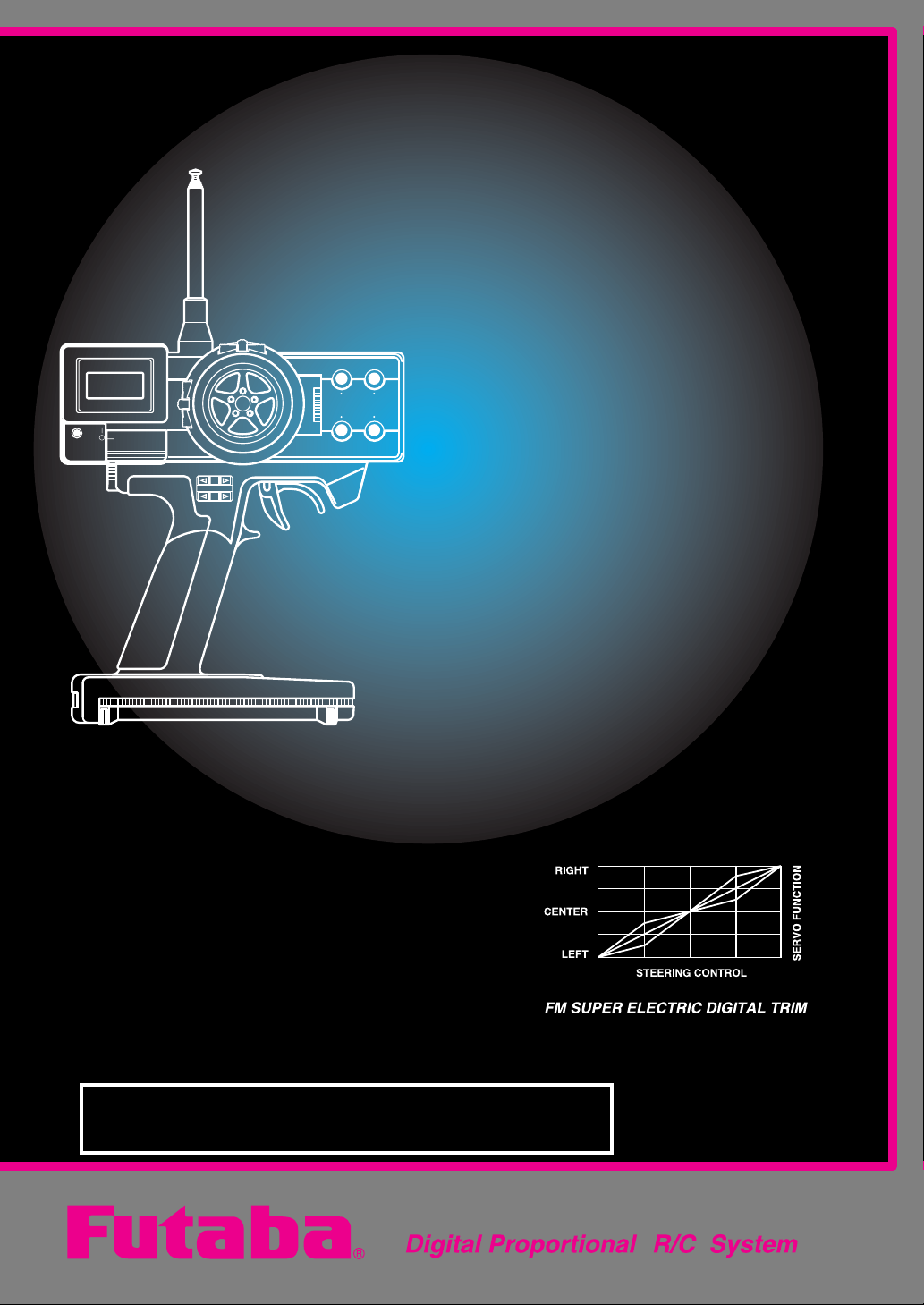
3PDF
Instruction
Manual
ForCar'sandBoat's
3ChannelDigitalProportionalR/CSystem
1M23N02102
Page 2
Thank you for purchasing the Futaba 3PDF.
Prior to operating your 3PDF, please read this manual thoroughly and use
your system in a safe manner.
After reading this manual store it in a safe place.
See the glossary on page (P36) for the definition’s of the special terms used in
this manual.
Application, Export and Reconstruction
1. Use this product in surface models only.
The product described in this manual is subject to regulations of the Ministry of
Radio/Telecommunications and is restricted under Japanese law to such purposes.
2. Exportation Precautions
(a) When this product is exported from Japan, its use is to be approved by the
Radio Law of the country of the destination.
(b) Use of this product with other than models may be restricted by Export and
Trade Control Regulations. An application for export approval must be submitted.
3. Modification, adjustment and replacement of parts.
Futaba is not responsible for unauthorized modification, adjustment and replacement of parts of this product.
THE FOLLOWING STATEMENT APPLIES TO THE
RECEIVER (FOR U.S.A.)
This device complies with part 15 of the FCC rules. Operation is subject to the
following two conditions.
(1) This devise may not cause harmful interference, and
(2) This devise must accept any interference received, including interference
that may cause undesired operation.
-No part of this manual may be reproduced in any form without prior permission.
-The contents of this manual are subject to change without prior notice.
-This manual has been carefully written, please write to Futaba if you feel that any corrections or clarifications should be made.
-Futaba is not responsible for the use of this product.
-Futaba is an registered trademark of Futaba Corporation.
Page 3

3PDF
Table of Contens
For your safety as well as
that of others.
Explanation of Symbols 2
Operation Precautions 2
Nicad Battery Handling Precautions
4
Other Precautions 4
Storage and Disposal Precautions
5
Prior to Operation
Features 6
Set Contents 7
Nomenclature / Handling 8
Digital Trim Operating Instructions
11
D/R ATL CH3 LeverOperating In-
structions 11
Display / Key Operation 12
Warning Displays 13
Precautions when turning the power
switches off and on. 13
Assembly
ダ
Receiver and Servo Connections
イ
レ
Assembly Safety Precautions 15
ク
Preparations Prior to Setting Trans-
mitter 16
ト
E.S.C. MC210CB Adjustment 17
モ
14
ー
ド
機
能
Function Map
Function Mode Group 18
System Mode Group 18
Direct Mode Group 19
Description of Functions
Steering Trim 20
Throttle Trim 21
Servo Reverse 22
Steering ATV 23
Throttle ATV 24
Steering D/R 25
Throttle ATL 26
Steering Exponential 27
Throttle Exponential 28
Model Select 29
Model Name 30
Lever Function Select 31
Channel 3 Function Selection 32
CH3 Position Setting 33
Reference
Ratings 34
Optional parts 34
Troubleshooting 35
Glossary 36
When requesting repair 37
For your safety
as well as that
of others.
Prior to
Operation
Assembly
Function
Map
Description
of
Functions
Reference
11
1
11
Page 4
3PDF
For your safety as well as that of others.
Use this product in a safe manner. Please observe the following safety precautions at
all times.
Explanation of Symbols
For your safety as well as that of others.
and must be observed.
Symbols Explanation
DANGER
Warning
Caution
Indicates a procedure which could lead to a dangerous situation and may cause death or serious injury if ignored and
not performed properly.
Indicates procedures which may lead to dangerous situations and could cause death or serious injury as well as superficial injury and physical damage.
Indicates procedures that may not cause serious injury, but
could lead to physical damage.
Symbols: ; Prohibited ; Mandatory
Operation Precautions
Warning
The parts of this manual indicated by the following symbols are extremely important
22
2
22
Prohibited Procedures
Do not operate two or more models
on the same frequency at the same
time.
Operating two or more models at same time on the
same frequency will cause interference and loss of
control of both models.
AM, FM (PPM) and PCM are different methods
of modulation. Nonetheless the same frequency
can not be used at the same point in time, regardless of the signal format.
Do not operate outdoors on rainy
days , run through puddles of water or
when visibility is limited.
Should any type of moisture (water or snow) enter any
compoent of the system, erratic opreation and loss of
control may occur.
Do not operate in the following
places.
-Near other sites where other radio control
activity may occur.
-Near people or roads.
-On any pond when rowboats are present.
-Near high tension power lines or communication broadcasting antennas.
Interference could cause loss of control . Improper installation of your Radio Control System in your model
could result in serious injury.
Do not operate this R/C system when
you are tired, not feeling well or under
the influence of alcohol or drugs.
Your judgment is impaired and could result in a dangerous situation that may cause serious injury to
yourself as well as others.
Page 5
Mandatory Procedures
Tx Rx
Tx: Transmitter
Rx: Receiver
Use genuine Futaba
crystal sets only.
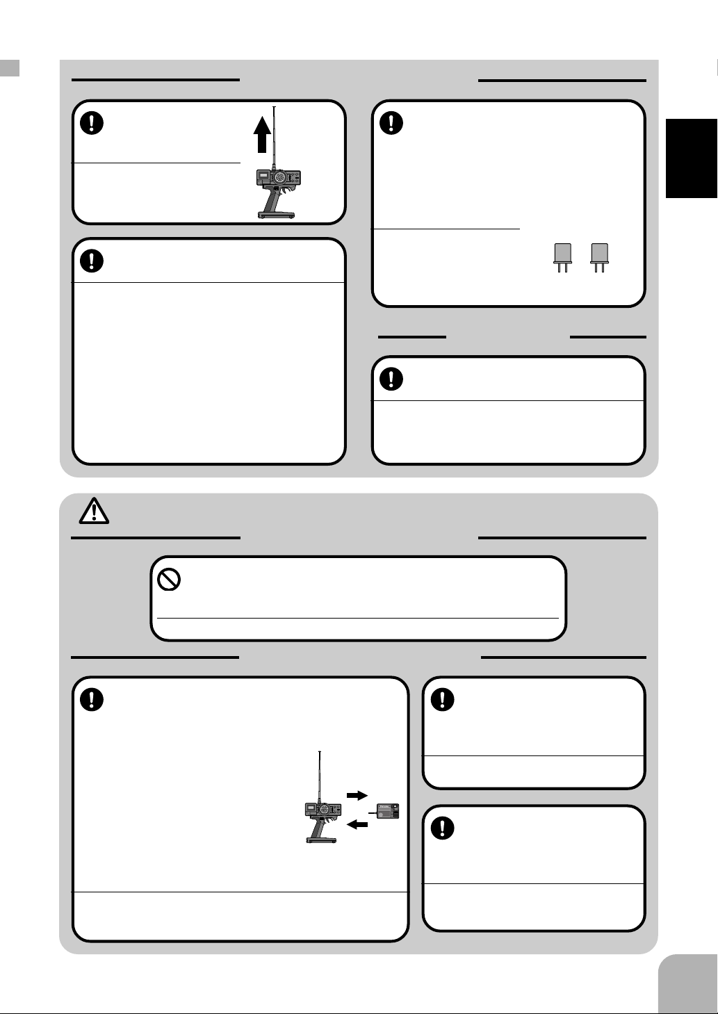
Extend the transmitter antenna to its full
length.
If the transmitter antenna is not
fully extended the operating
range of the radio will be re-
duced.
Extend to
full length
Always perform a operating range
check prior to use.
Problems with the radio control system as well as im-
proper installation in a model could cause loss of con-
trol.
(Simple range test method)
Have a friend hold the model, or clamp it down or
place it where the wheels or prop can not come in
contact with any object. Walk away and check to
see if the servos follow the movement of the controls on the transmitter. Should you notice any abnormal operation, Do not operate the model. Also
check to be sure the model memory matches the
model in use.
Caution
Prohibited Procedures
When changing the frequency, be
sure to always use genuine Futaba
crystal sets (transmitter and receiver)
as specified in this manual. (Changing the frequency crystals in systems
on 75MHz is illegal per FCC regulations)
If other brands of crystals are
used the system may not operate or the operating range
may be reduced.Loss of control will occur .
Item Check
Check the transmitter antenna to be
sure it is not loose.
If the transmitter antenna works loose, or is disconnected while the model is running signal transmission
will be lost. This will cause you to lose control of the
model..
For your safety as well as that of others.
1. Turn on the transmitter power switch.
2. Turn on the receiver or speed control
power switch.
Turning off the power switches
Always be sure the engine is not
running or the motor is stopped.
1. Turn off the receiver or speed control power switch.
2. Then turn off the transmitter power switch.
If the power switches are turned off in the opposite
order the model may unexpectedly run out of control
and cause a very dangerous situation.
Do not touch the engine, motor, speed control or any part of
the model that will generate heat while the model is operating
or immediately after its use.
These parts may be very hot and can cause serious burns.
Mandatory Procedures
Turning on the power switches.
Always check the throttle trigger on the
transmitter to be sure it is at the neutral
position.
Power ON
Power OFF
When making adjustments to
the model do so with the engine not running or the motor
disconnected.
You may unexpectedly lose control and
create a dangerous situation.
FP-R113F
FM
1
2
3
B/C
When operating your model
always display a frequency
flag on your transmitter antenna.
When you change the frequency, also
change the flag to the corresponding channel.
33
3
33
Page 6
Nicad Battery Handling Precautions
Shock
Prohibited
(Only when Nicad batteries are used)
Warning
Mandatory Procedures
For your safety as well as that of others.
Always check to be sure your batteries have been charged prior to operating the model.
Should the battery go dead while the model is operat-
ing loss of control will occur and create a very danger-
ous situation.
When the model is not being used,
always remove or disconnect the
Nicad battery .
Should the battery be left connected this could create
a dangerous situation if someone accidentally turns
on the receiver power switch. Loss of control would
occur.
Caution
Prohibited Items
Do not use commercial AA size Nicad
batteries.
Quick charging may cause the
battery contacts to overheat and
damage the battery holder.
Use
prohibited
Nicad AA size
batteries.
To recharge the transmitter Nicad ,
use the special charger made for this
purpose.
Overcharging could cause the Nicad battery to overheat, leak or explode. This may lead to fire, burns,
loss of sight and many other type's of injuries.
Special
Charger
Do not drop the Nicad battery or expose it to strong shocks or vibrations.
The battery may short circuit and overheat, electrolyte
may leak out and cause burns or chemical damage.
44
4
44
Do not short circuit the Nicad battery
terminals.
Causing a short circuit across the battery terminals
may cause abnormal heating, fire and burns.
Other Precautions
Caution
Prohibited Procedures
Do not expose plastic parts to fuel,
motor spray, waste oil or exhaust.
The fuel, motor spray, waste oil and exhaust will pen-
etrate and damage the plastic.
Mandatory Procedures
Always use only genuine Futaba
transmitters, receivers, servos, FET
amps (electronic speed
controls),Nicad batteries and other
optional accessories.
Futaba will not be responsible for problems caused by
the use of other than Futaba genuine parts. Use the
parts specified in the instruction manual and catalog.
Page 7
Storage and Disposal Precautions
Warning
Prohibited Procedures
Do not leave the radio system or
models within the reach of small children.
A small child may accidentally operate the system,
this could cause a dangerous situation and injuries.
Nicad batteries can be very dangerous when mis-
handled and cause chemical damage.
Do not throw Nicad batteries into a
fire. Do not expose Nicad batteries to
extreme heat. Also do not disassemble or modify a Nicad battery
pack.
Overheating and breakage will cause the electrolyte
to leak from the cells and cause skin burns, loss of
sight as well as other injuries.
<Nicad Battery Electrolyte>
The electrolyte in Nicad batteries is a strong alkali. Should you get even the
smallest amount of the electrolyte in your eyes, DO NOT RUB, wash immediately with water, seek medical attention at once. The electrolyte can cause blindness. If electrolyte comes in contact with your skin or clothes, wash with water
immediately.
Mandatory Procedures
When the system will not be used for
any length of time store the system
with batteries in a discharged state.
Be sure to recharge the batteries prior
to the next time the system is used.
If the batteries are repeatedly recharged in a slightly
discharged state the memory effect of the nicad battery may considerably reduce the capacity . A reduction in operating time will occur even when the batteries are charged for the recommended time.
For your safety as well as that of others.
Caution
Prohibited Procedures
Do not store your R/C system in the
following places.
- Where it is extremely hot or cold.
- Where the system will be exposed to direct
sunlight.
- Where the humidity is high.
-Where vibration is prevalent.
-Where dust is prevalent.
-Where the system would be exposed to
steam and condensation.
Storing your R/C system under adverse conditions
could cause deformation and numerous problems
with opreation.
<Nicad Battery Recycling>
A used Nicad battery is valuable resource. Insulate the battery terminals and
dispose the battery by taking it to a battery recycling center.
Mandatory Procedure
If the system will not be used for a
long period of time remove the batteries from the transmitter and model
and store in a cool dry place.
If the batteries are left in the transmitter electrolyte
may leak and damage the transmitter. This applies to
the model also, remove the batteries from it also to
prevent damage.
55
5
55
Page 8

3PDF
-Multiple Model Memory (3 Models)
A model name can be assigned each memory using six alphabetic,
numeric and symbolic characters. (P30)
Digital Trim Memory will recall all trim settings. As you go from
model to model memory all trim settings will not have to be reset.
Prior to operation
Features
Prior to operation
All program information is displayed on a 8 character 2 line display. The large display is easy to read.
-The third channel can be used to match your
application in specialty models.
-Large LCD Display
The third channel can be used in five operation modes.(P32)
-Digital Trim
Digital trim will allow positive and quick settings to be made.
-Lever Function Selection (P31)
This function applies to D/R, ATL and 3rd channel levers.. Since
they are digital, when you change the model memory these will not
require you to readjust the settings . They will be where they were
the last time that model memory was used.
-New Lightweight and Balanced Design
-Trigger Brake Stop (Mechanical ATL) (P8)
-Body Rest can be used (Option)
66
6
66
-Servo Reverse Function (P22) / Steering
ATV Function (P23) / Steering D/R function
(P25) / Throttle ATV Function (P24) / Throttle
ATL Function (P26)
Page 9

Set Contents
After opening the container, check the contents for the following items. The contents
will vary with the system purchased.
Transmitter
Receiver
Servo
E.S.C.
Switch
Transmitter
/ Receiver
System with
2 servos
T3PDF (x1)
R113F (x1)
S3003 (x2 )
CSW-GS (x1)
or (none)
System with
1 MC210CB
S3003 (x1)
MC210CB (x1)
Prior to operation
Battery
Holder
Miscellaneous
R2-BSS-B (x1)
or (none)
Servo mounting hardware and servo horns
Mini Screwdriver
-Should any item be missing or you are uncertian of the contents of the system, please
contact the dealer where the system was purchased.
77
7
77
Page 10
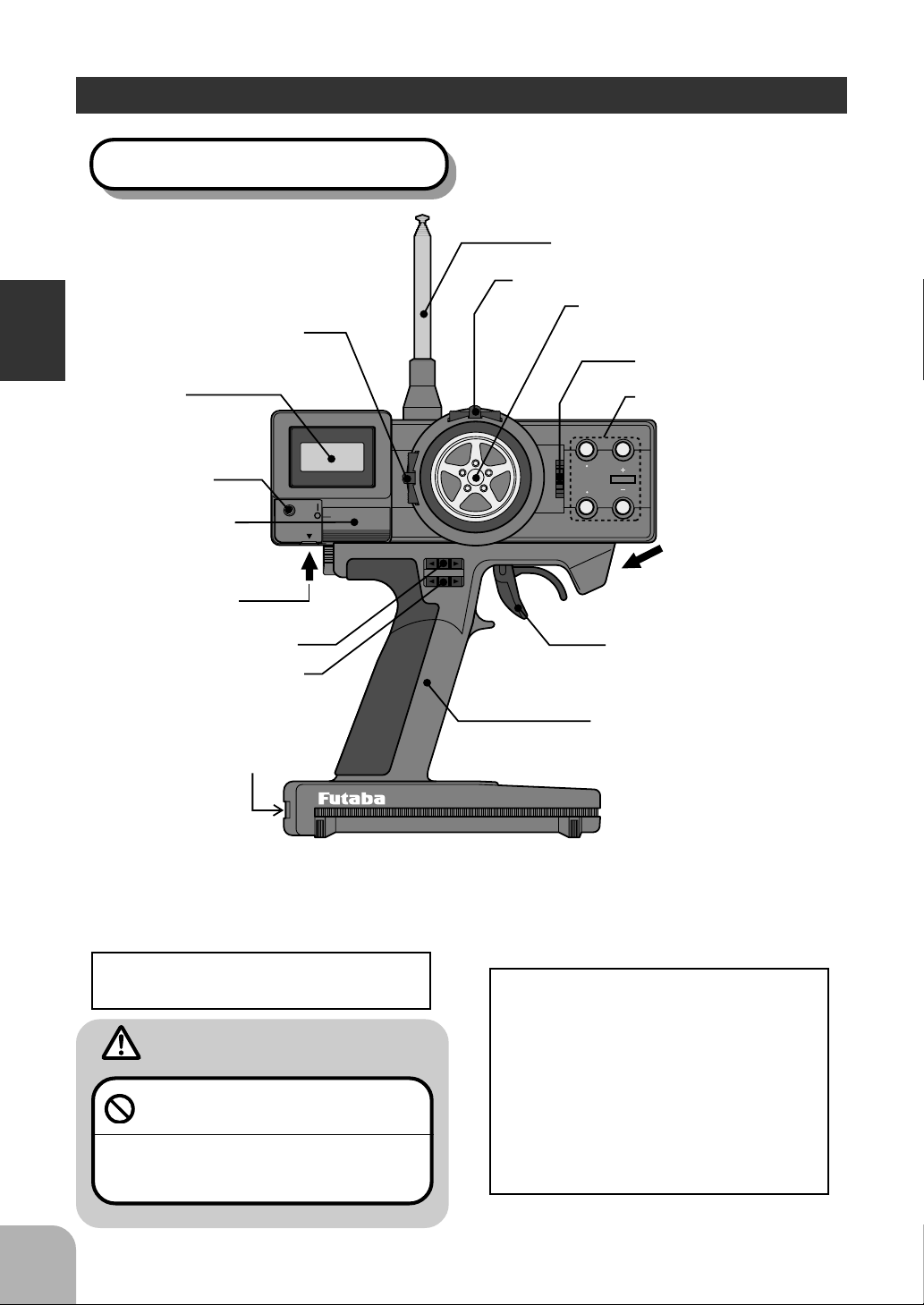
Transmitter T3PDF (Front)
Throttle Trim
Prior to operation
LCD
Screen
Nomemclature / Handling
Antenna
Steering Trim
Steering Wheel
Channel 3
Lever
Edit Keys
MULTI FUNCTION DISPLAY
Power LED
Power Switch
DOT MATRIX
POWER
CHARGE
Charging Jack
Steering D/R Lever
Throttle ATL Lever
Body Rest
Mounting Hole
* In the figure above the levers are shown in the neutral position.
Charging Jack
This jack is used to charge Nicad bat-
tery when used.
Caution
Never charge a dry cell type (NonNicad) battery.
Charging a non nicad type battery may damage the
transmitter, and could cause the battery electrolyte
to leak and cause additional damage.
DIGITAL PROPORTIONAL RADIO CONTROL SYSTEM
Mechanical ATL
The throttle trigger travel can be adjusted to limit the brake stroke.
-Adjustment Method
When the screw is turned clockwise
the brake stroke will become shorter.
When the screw is turned counter
clockwise the stroke becomes longer
as shown in the figure above.
MODE
RESET
SELECT
Mechanical ATL
Adjustment Hole
Throttle Trigger
Grip Handle
88
8
88
Page 11
Transmitter T3PDF (Rear)
When the battery alarm sounds
change the batteries, or if Nicads are
used recharge.
(Alarm voltage: approx. 8.7 Volts)
Crystal
Transmitter T3PDF (Bottom)
Handling the batteries (8 AA size batteries)
Battery Replacement
1Open the battery cover by slid-
ing in the direction of the arrow
shown in the figure.
2Remove used batteries.
Battery Cover
Open
Batteries
(8 AA Size
Batteries)
Prior to operation
Caution
Be sure to load the batteries in the
correct polarity order.
If the polarity is reversed the transmitter may be
damaged.
3Load the new AA size batteries.
Pay very close attention to the
polarity markings and reinsert
accordingly.
4Slide the battery cover back
into place.
<Check>
Turn the power switch on and check
voltage displayed on the LCD screen.
With new batteries the voltage dis-
played should be around 12 volts.
If the displayed voltage is low or does
not light all, check the batteries for in-
sufficient contact or incorrect battery
polarity.
When the system will not be used
for any length of time remove the
batteries.
If the batteries do happen to leak, clean the battery
contacts thoroughly. Make sure the contacts are
free of corrosion.
<Battery Disposal>
Some states require special handling
when any type of battery is disposed.
Contact the State Agency responsible
for recycling hazardous waste for procedures in your area.
<Converting to Nicad Batteries>
Purchase Futaba Part Number NT8JY to convert your transmitter to
Nicad use.
99
9
99
Page 12
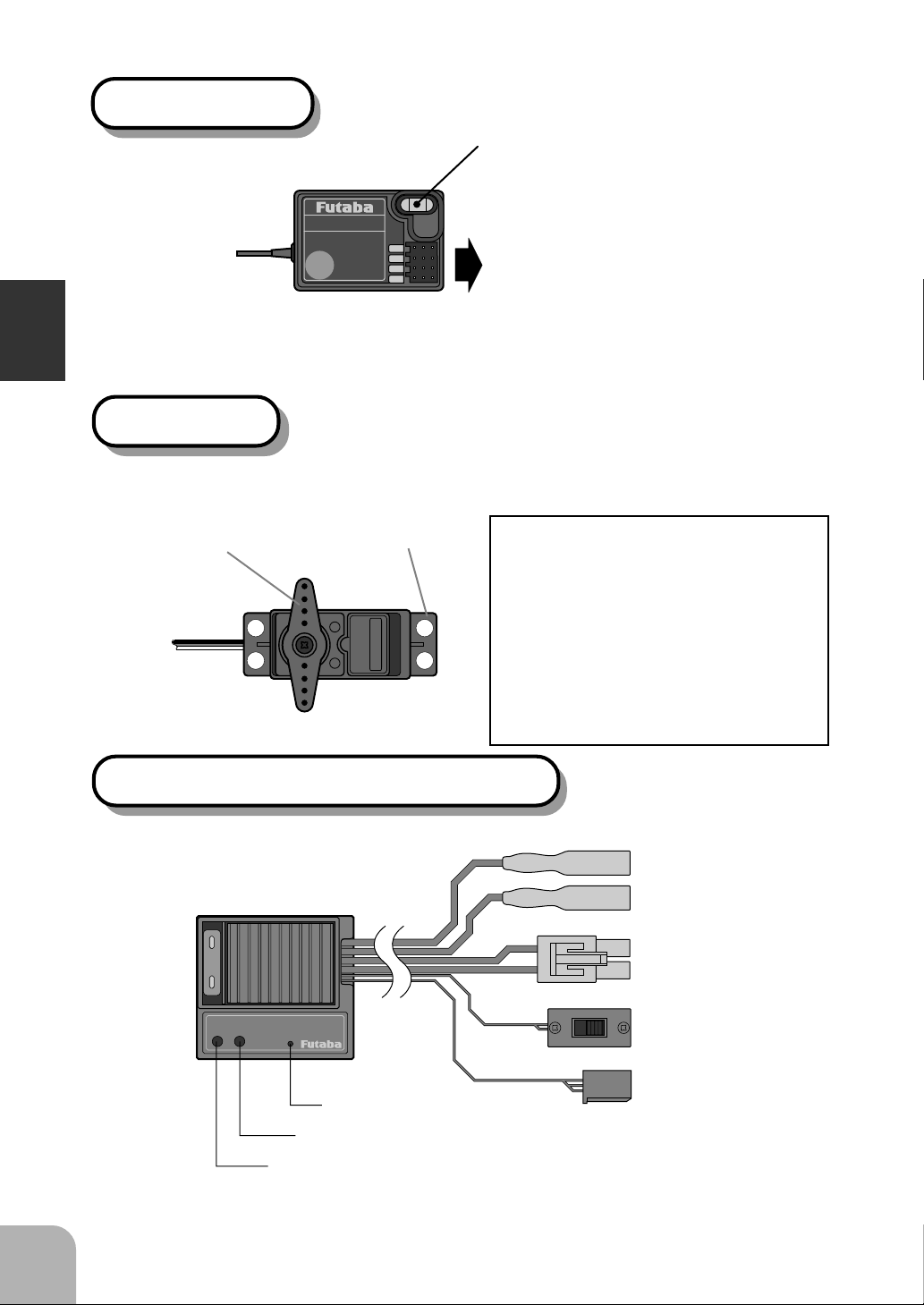
Receiver R113F
Crystal
Antenna
Prior to operation
Servo S3003
Servo Horn
To Receiver
FP-R113F
FM
1
2
3
B/C
Mounting Flange
Output Connector
“1”: Steering Servo (Ch1)
“2”: Throttle Servo (Ch2)
“3”: CH3 Servo (CH3)
Power Connector
<Accessories>
The following accessories are supplied with the system;
-Spare servo horns: Use to match
your application.
-Servo mounting hardware: Rubber
bushing, grommet, wood screws.
(For mounting precautions see
pages 15.)
1010
10
1010
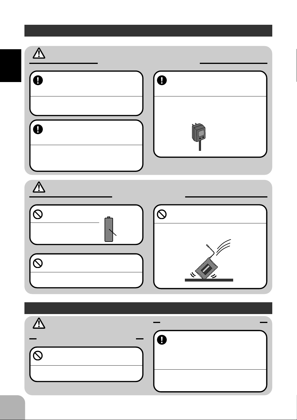
Electronic speed control MC210CB
MC 210CB
Monitor Lamp
Neutral Point Trim
High Point Trim
Connects
to Motor
Connects
to Battery
ON
Power
OFF
switch
Connects
to Receiver
Page 13

Digital Trim Operating Instructions
To operate the digital trim push the trim lever to the left or right.
-A “Tone” will indicate each step.
-When the trim movement reaches its maximum travel the “tone” will change pitch.
-When a trim lever is moved the current trim position will be displayed on the LCD
screen.
Steering Trim
Lever
Throttle Trim
Lever
Prior to operation
D/R ATL CH3 Lever Operating Instructions
Operate the levers by pushing them to the left or right (up or down).
-A “Tone” will indicate each step.
-When a lever reaches its maximum travel the pitch of tone will change.
-When a lever is moved its current position will be displayed on the LCD screen.
ATL Lever D/R Lever
Channel 3
Lever
MODE
SELECT
RESET
1111
11
1111
Page 14

Initial Screen (Normal Screen)
Model Number Display (1~3)
Displays the number currently in use.
Prior to operation
LCD screen contrast adjustment
1Turn on the transmitter power switch , the screen
will show the current settings.
2Adjust the Contrast by pressing the + or - key
while pressing the Select key at the same time.
-The Contrast can be adjusted in 4 steps.
+ key: darker
- key: Lighter
Display / Key Operation
Model name display (only when set)
(6 characters)
Batttery voltage display
Displays the current
transmitter battery
voltage lavel.
Edit Keys
Mode Key
Used to select the function
Select Key
Used to select the channel, etc. at
the function screen.
1212
12
1212
MODE
SELECT
RESET
+ Key / - Key
Used to input data at the function
screen.
Page 15

Warning Displays
Low Battery Warning
When the transmitter battery voltage drops to 8.7 volts or less. A audible alarm will
sound and the message “Low Batt” will appear on the display screen. Replace or
recharge the batteries when you hear this alarm.
LCD Screen: Audible Alarm:
Continuous Tone will sound.
Warning
When the low battery alarm is heard, immediately stop operating the model. Retrieve
the model and turn off the power switches in the proper order (Receiver then Transmitter).
A discharged battery will no longer operate the transmitter and cause loss of control.
Memory Error
Prior to operation
If the data is destroyed for any reason an audible alarm will sound. The message
“MEMORY ERROR” will appear on the display screen as a warning.
LCD Screen:
Audible Alarm:
Continuous Tone will sound.
Warning
When a memory error is generated immediately stop operating the system and request
repair by the Futaba service center.
If you continue to operate the system control may be erratic and cause of control is highly likely.
Precautions when turning the power switches off and on.
If the power switches are turned off within 2 seconds after the data has been changed
by using the edit keys or trim levers. The information may not be retained by the
memory.
1313
13
1313
Page 16

3PDF
Assembly
Receiver and Servo Connections
Connect and install the receiver and servos in accordance with the "Assembly Safety
Precautions" on the next page.
When a E.S.C. is used (MC210CB)
Connect to motor
Connect to battery
Assembly
Gas Powered Model
Connect to
receiver battery
MC 210CB
E.S.C.
(Electronic speed control)
FP-R113F
FM
1
2
3
B/C
Receiver
FP-R113F
FM
Receiver
1
2
3
B/C
(B)
Power Switch
(1CH)
(2CH)
(1CH)
(2CH)
(3CH)
ON
OFF
Power Switch
Steering Servo
Steering Servo
Throttle Servo
Channel 3 Servo
1414
14
1414
Page 17

Assembly Safety Precautions
Warning
Connector Connections
Be sure the receiver, servo and battery connectors are fully and firmly
connected.
If vibration from the model cause a connector to work
loose while the model is in operation. You may lose
control .
Receiver Vibration Damping and
Waterproofing
(Car)
Dampen the vibration to the receiver
by mounting to the chassis or mounting plate with thick double sided tape
in electric powered models. In gas
powered models wrap the receiver in
foam and mount it where the vibration
is the least prevalent.
(Boat)
Dampen the vibration to the receiver
by wrapping it in foam. Waterproof by
placing it in plastic bag or watertight
radio box in model.
If the receiver is subjected to strong vibration or shock
erratic or loss of control may occur. If any moisture
comes in contact the receiver and servos you may
expertise the same result as well as damage to the
system.
Electronic speed control
Install the heat sinks where they will
not come in contact with aluminum,
carbon fiber or other parts that conduct electricity.
If the FET Amp (Electronic speed control) heat sinks
touch other materials that conduct electricity a short
circuit could occur. This could result in loss of control
and damage to the system.
Servo Throw
Operate each servo over its full stroke
and be sure the linkage does not bind
or is loose.
The continuous application of unreasonable force to a
servo may cause damage and excessive battery
drain.
Servo Installation
When you install the servos always
use the rubber grommets provided in
servo hardware bags. Mount the servos so they do not directly come in
contact with the mount.
If the servo case comes in direct contact with the
mount vibration will be directly transmitted to the
servo.
If this condition continues for a long time the servo
may be damaged and control will be lost.
Assembly
Receiver Antenna
Do not cut or bundle the receiver antenna
Do not bundle the receiver antenna
together with the servo lead wires
Keep the receiver antenna at least 1
inch away from the motor and battery
and wires that handle heavy current
loads..
Cutting, bundling or routing the receiver antenna near
any devise that produce noise will reduce the operat-
ing range of the system and result in loss of control.
*Also route the receiver antenna away from metal,
carbon fiber and other parts that conduct electricity. These parts can transmit high frequency noise.
Motor Noise Suppression
Always install capacitors to suppress
noise when electric motors are used.
If capacitors are not properly installed you could experience erratic operation and reduced range as well
as loss of control.
Other Noise Suppression Methods
Be sure there are no metal parts in
your model which under vibration can
come in contact with other metal
parts.
Metal to metal contacts under vibration will omit a high
frequency noise that will effect the receivers performance. You could experience erratic operation and
reduced range as well as loss of control.
1515
15
1515
Page 18

Preparations Prior to Setting Transmitter
Prior to making any setting on the transmitter check the following items.
Assembly
2
Throttle Trim Lever
TRIM.Pos
TH 0
3
Lever A
D/R .Pos
L100R100
1
Steering Trim Lever
TRIM.Pos
ST 0
4
Lever B
ATL .Pos
100
Preparations Prior to Setting Transmitter
1To set the steering trim to neutral, push the channel 1 trim lever to the left
or right. The display will read TRIM.Pos. Hold the lever to the left or right
until you set 0 on the display. This will be the neutral position.
2To set the throttle trim to neutral, push the channel 2 trim lever up or down.
The display will read TRIM.Pos. Hold the lever up or down until you see 0
on the display. This will be the neutral position..
3To set Grip Dial A to maximum, push the upper lever to the left or right. The
display will read GDA. Hold the lever to the right or left. The maximum
setting will be L100 R100.
4To set Grip Dial B to maximum, push the lower lever to the left or right. The
display will read GDB.Pos ATL. Hold the lever to the left or right. The maximum setting will be 100.
1616
16
1616
Page 19

E.S.C. MC210CB Adjustment
*Use the accessory mini screwdriver to make adjust-
ments.
Preparation
1Set the transmitter servo reversing switch to the
normal position.
2Turn the high point trim fully clockwise.
Neutral Adjustment
1Have the throttle trigger at neutral.
2Set the neutral trim to the point where the monitor
lamp goes off.
- The point where the monitor lamp changes from a rapidly flashing light
to off is the neutral point.
High Point Adjustment
1Set the throttle trigger to just a little before full
throttle.
2Set the high point trim to the point where the
monitor lamp is a steady light.
- The point where the monitor lamp changes from a rapidly flashing to a
steady light is full throttle.
MC210CB
Fully Clockwise
MC210CB
Point at which monitor
lamp goes off.
MC210CB
Point where the monitor
lamp is a steady light.
Assembly
Monitor Lamp
NeutralPoint HighPoint
Reverse Forward
SlowFlashingOffRapidlyFlashingSteadyLight
1717
17
1717
Page 20

3PDF
Function Map
When the Mode key is pressed from the initial
screen where the voltage is displayed , this will
call the FUNCTION MODE.
FUNCTION
MODE
Function Mode
Function Map
MDL.SEL
When the MODE key and the SELECT key are
pressed simultaneously at the initial screen.,
this will call the SYSTEM MODE.
P12
1:
10.5V
Initial Screen
Pressed
Simultaneously
SELECT
MODE MODE
MODE
Select key
pressed first
SELECT
SYSTEM
MODE
System Mode
Each different
function screen
can be sequen-
MODE
tially called by
pressing the
MODE key.
P29
MODE
P22
REVERSE
Pressed
Simultaneously
SELECT
MODE
Each different
function screen
can be sequentially called by
pressing the
MODE key.
Model Select
MODE
P23
ST.ATV
Steering ATV
MODE
P27
ST.EXP
Steering Exp
Function Mode
Group
MODE
TH.EXP
Throttle Exp
MODE
TH.ATV
Throttle ATV
MODE
P28
P24
Servo Reverse
MODE
P32
AUX.SEL
Channel 3 Select
Function
MODE
System Mode
Group
MODE
P30
MDL.NAME
Model Name
MODE
P31
GD.SELCT
Dial Function Select
1818
18
1818
Page 21

When a lever is operated from an
arbitrary screen, that screen is displayed for about 5 seconds.
* However, when the system mode
setup screen is displayed, the direct mode screen is not displayed
even if a lever is operated.
P20
TRIM.Pos
ST
Steering Trim
Position
*Initial Setting: Channel 3
P21
TRIM.Pos
TH
Throttle Trim
Position
P25
D/R .Pos
Lever A
Position
*Initial Setting: Steering D/R
Direct Mode
Group
P33
CH3 .Pos
Lever C
Position
P26
ATL .Pos
Lever B
Position
*Initial Setting: Throttle ATL
Function Map
1919
19
1919
Page 22

3PDF
Description of Functions
Steering Trim
The steering neutral position can be adjusted by moving
the steering trim lever to left or right.
Use this function to make your model run in a straight
line.
1At the initial screen where the Model number and
Voltage are displayed the Steering Trim setting
can be viewed by pressing the Trim lever to the
left or right. If the Steering trim is not operated
for 5 seconds the display will return to the initial
screen.
-When the SYSTEM MODE GROUP is displayed the steering trim position will be displayed.
Racers Tip
Adjust the servo horn and linkage so they are parallel. If
you are using a servo saver be sure the Steering trim is as
close to neutral as possible. Check the transmitter steer-
ing trim and be as close to 0 as you can. Also check the
Description of Functions
instruction manual of the model this system is to be in-
stalled in for the correct servo position.
Steering Trim
Lever
2020
20
2020
Servo Saver
90°
Parallel
Trim Operation and Maximum Travel
Trim adjustments will change the servo movement
range. When you make large trim adjustments recheck
your maximum servo travel. (Steering ATV Right side
and Left side)
When Trim Adjustments are Large
When the trim adjustments have caused the neutral to
shift considerably to the left or right you may need to
readjust the linkage.
Direct Servo
Saver Horn
90°
Page 23

Throttle Trim
The Throttle neutral position can be adjusted by moving
the throttle trim lever up or down.
1At the initial screen where the Model number and
voltage are displayed the Throttle Trim setting
can be viewed by pressing the trim lever up or
down. If the Throttle trim is not operated for 5
seconds the display will return to the initial
screen.
-When a System Mode Group screen is displayed the throttle trim position will not be displayed.
Racers Tip
When using a FET Amp (Electronic speed control) set
the screen to 0 and make the neutral adjustments at the
FET Amp. For gas powered models adjust the throttle
linkage as descried in the engine instruction manual.
When 0 is displayed the carburetor should be fully
closed
Carburetor Fully Closed
(Drum Type) (Slide Type)
Trim Operation and Maximum Travel
Trim adjustments can change the servos overall travel. If
large adjustments are made you may need to readjust the
brake side movement. Check the Throttle ATV B side
and the Throttle ATL. The forward may not be effected
but should be checked.
Throttle Trim Lever
Description of Functions
When Trim Adjustments are Large
When the trim adjustment is large enough to cause the
neutral to shift considerably to the forward or brake side
you may need to readjust the linkage.
2121
21
2121
Page 24

Servo Reverse
This function will reverse the rotation direction of the
Steering, Throttle and Channel 3 servos.
If the trim position is not set to 0. The servo will
shift the same amount off neutral on the opposite
side when the servo is reversed.
1Access the SYSTEM MODE by pressing the SE-
LECT and MODE Keys simultaneously
SELECT
MODE
2Access the Servo Reversing Function screen by
pressing the MODE KEY Once.
MODE
1:
10.5V
SELECT
MODE
SYSTEM
MODE
MODE
REVERSE
MODE
AUX.SEL
MODE
System Mode
Group
Initial Screen
Select key
pressed first
MODE
MDL.NAME
MODE
GD.SELCT
3Select the channel you wish to change by press-
ing the SELECT KEY.
ST: Steering
TH: Throttle
Description of Functions
CH3: Channel 3
(Direction Setting)
4Change the rotation direction with the + or - key.
NOR: Forward Direction
REVE: Reverse Direction
Channel 3 Operation
When CH3 (operation function selection) is set to 1P-4P,
the lever direction versus position movement can be
changed.
SELECT
2222
22
2222
Page 25

Steering ATV
Use this function to limit the servo movement to the left
or right. The servo travel to each side can be indepen-
dently adjusted. This feature will compensate for any
difference in right or left turning angles or radius due to
the characteristics of your model.
Warning
Be sure that the steering linkage does not bind or come
in contact with any suspension parts or arms.
If unreasonable force is applied to the servo. The servo may be damaged
could cause loss of control.
(Steering ATV Selection)
1Access the FUNCTION MODE by pressing the
MODE key from the initial screen.
MODE
2Access the Steering ATV Function by pressing
the MODE KY two times.
1:
10.5V
MODE
FUNCTION
MODE
MODE
MDL.SEL
MODE
ST.ATV
MODE
ST.EXP
Function Mode
Group
Initial Screen
MODE
TH.EXP
MODE
TH.ATV
MODE
MODE
(Steering right side adjustments)
3With the steering wheel turned fully to the right
adjust the right side travel by pressing the + or key.
(Steering Left Side Adjustment)
4With the steering wheel turned fully to the left ad-
just the left side travel with the + and - keys.
When you want to adjust both directions simulta-
neously.
When the + key or - key are operated when the steering
wheel is at the neutral position the right side and left side
directions change simultaneously.
Description of Functions
Setting Range: 0~120
(Pressing the + key and - key simultaneously returns the initial
setting 100)
2323
23
2323
Page 26

Throttle ATV
FUNCTION
MODE
1:
10.5V
ST.ATV
TH.ATV
ST.EXP
TH.EXP
MDL.SEL
MODE
MODE
MODE
MODE
MODE
MODE
MODE
Initial Screen
Function Mode
Group
This function is used to adjust the forward and brake side
servo travel. Each direction can be adjusted independent
of each other. Use this feature to set the throttle servo
travel.
Warning
Be sure that your throttle linkage does not apply excessive force to the servo.
If your linkage installation causes an unreasonable amount of force to be ap-
plied to the servo. The servo may be damaged and result in loss of control.
(Throttle ATV Selection)
1Access this function by pressing the MODE KEY
from the initial screen.
MODE
2Access the THROTTLE ATV screen by pressing
the MODE KEY four times.
Description of Functions
(Throttle Forward Side Adjustment)
3Pull the throttle trigger back and adjust the for-
ward side travel by pressing the + or - key. When
a FET Amp (Electronic speed control) is used set
to 100.
(Throttle Brake Side Adjustment)
4First set the ATL lever to the maximum travel po-
sition (100).
5Push the throttle trigger fully forward adjust the
servo travel by pressing the + and - keys.
When an FET Amp (Electronic speed control) is
used set to 100.
MODE
Setting Range: 0~120
(Pressing the + and - keys simultaneously returns setting to initial
value 100)
Setting Range: 0~120
(Pressing the + and - keys simultaneously returns the initial value
100)
2424
24
2424
Page 27

Steering D/R
(Description when D/R lever is assigned to GDA )
This function is used to limit the steering servo travel.
This feature will limit the servo travel equallyin both
directions. If the car tends to understeer (push) when
cornering add servo travel. If the car tends to over-
steer (loose) take servo travel out.
1At the initial screen or a Function Mode Group
screen . The D/R position will be displayed by
pressing the D/R lever to the left or right. If the
lever is not operated for 5 seconds the display
will return to the initial screen.
When a SYSTEM MODE GROUP screen is displayed the D/R position
will not be displayed.
2Adjust the steering servo travel by pressing the
D/R lever to the left or right.
D/R Lever
Setting Range: 0~120
(The maximum travel can also be
limited by the ATV function)
Description of Functions
2525
25
2525
Page 28

Throttle ATL
(Description when ATL is assigned to GDB)
This function is used to adjust the brakes. If you are
getting to much brake in the car set the ATL number
to lower setting. When you need more brakes set the
number to a higher setting.
1At the initial screen or Function Mode Group
screen. The ATL will be displayed by pressing
the ATL lever to the left or right. If the ATL lever is
not operated for 5 seconds the screen will return
to the initial screen.
If a SYSTEM MODE screen is displayed the ATL position will not be
displayed.
ATL Lever
2Adjust the brake side servo travel by moving the
ATL lever to left or right.
Description of Functions
Setting range: 0~ 120
(The maximum setting is the
travel set at the throttle brake
side)
2626
26
2626
Page 29

Steering Exponential
FUNCTION
MODE
1:
10.5V
ST.ATV
TH.ATV
ST.EXP
TH.EXP
MDL.SEL
MODE
MODE
MODE
MODE
MODE
MODE
MODE
Initial Screen
Function Mode
Group
Use this function to change the sensitivity of the steering
servo around neutral. The - side will make the servo less
sensitive around neutral. The + side will make the servo
more sensitive around the neutral.
Racer Tip
When the handling characteristics of a model are un-
known begin at 0%. At 0% the servo movement is linear.
1Access this function by pressing the MODE KEY
from the initial screen.
MODE
(Steering EXP Selection)
2Access the Steering EXP screen by pressing the
MODE KEY three times.
MODE
(EXP Adjustment)
3When you want the servo reaction to be move
sensitive adjust with the + key. When you want
the servo reaction to be less sensitive adjust with
the - key.
Setting Range: -100~0~+100
(Pressing the + and - keys simultaneously will return the setting to
the initial value 0.)
Description of Functions
2727
27
2727
Page 30

Throttle Exponential
FUNCTION
MODE
1:
10.5V
ST.ATV
TH.ATV
ST.EXP
TH.EXP
MDL.SEL
MODE
MODE
MODE
MODE
MODE
MODE
MODE
Initial Screen
Function Mode
Group
This function will allow you to change the sensitivity of
the throttle servo. The + side will make the servo reac-
tion move sensitive while - side will make it less sensi-
tive.
Racers Tip
When track conditions are good experiment with the +
side. When track conditions are not ideal experiment
with the - side.
1Access the function by pressing the MODE KEY
from the initial screen.
MODE
(Throttle EXP Selection)
2Access the Throttle EXP screen by pressing the
MODE KEY five times.
3Pull the throttle trigger fully back. When you want
the servo reaction to be more sensitive adjust
Description of Functions
with the + key. When you want the servo to less
sensitive adjust with the - key.
(Brake Side Adjustment)
4Push the throttle trigger fully forward. When you
want the servo to react quickly adjust with the +
key. When you want the servo to react mildly adjust with the - side.
When E.S.C. (With reverse) is used.
The EXP function will not be dynamically be felt in re-
verse.
MODE
Setting Range: -100~0+100
(Pressing the + and - keys simultaneously returns setting to initial
value 0 )
Setting Range: -100 ~ +100
(Pressing the + and - keys simultaneously returns the setting to
the initial value 0 )
2828
28
2828
Page 31

Model Select
FUNCTION
MODE
1:
10.5V
ST.ATV
TH.ATV
ST.EXP
TH.EXP
MDL.SEL
MODE
MODE
MODE
MODE
MODE
MODE
MODE
Initial Screen
Function Mode
Group
The 3PDF can store the data for 3 different models.
TheMODELSELECTfunctionisusedto accesseachmodel
memory.Usethisfunctionwhenyouchangefrom onemodel
toanother.
1Access this function by pressing the MODE key
from the initial screen.
MODE
(Model Select Function>
2Access the model select screen by pressing the
Mode key two times.
MODE
(Model Number Selection)
3Call the desired model number with the + or -
key.
Description of Functions
2929
29
2929
Page 32

Model Name
Up to 6 characters can be used to assign each model
memory a name. Alphabetic, numeric and symbols can
be used. This will make your model memos easy to tell
apart.
1Access the SYSTEM MODE by pressing the
MODE KEY and SELECT KEY simultaneously
from the initial screen.
SELECT
MODE
(Model Name Selection)
2Access the model name screen by pressing the
MODE key four times.
MODE
(Selection of characters to changed or used)
1:
10.5V
SELECT
MODE
SYSTEM
MODE
MODE
REVERSE
MODE
AUX.SEL
MODE
System Mode
Initial Screen
Select key
pressed first
MODE
MDL.NAME
MODE
GD.SELCT
Group
3Select the character you want by pressing the
SELECT key.
Description of Functions
(Setting New Character)
4Set the new character with the + and - keys
* Pressing the + and - keys simultaneously will
erase all the characters assigned to that model
memory name.
SELECT
Usable Characters
3030
30
3030
Page 33

Lever Function Select
This function will allow you to assign different functions
to the levers. The steering D/R Throttle ATL and Chan-
nel 3 can be assigned to these levers.
1Access the System mode by pressing the Mode
key and Select key simultaneously from the initial screen.
SELECT
MODE
(Lever function select selection)
2Access the lever function select screen by press-
ing the Mode key three times.
MODE
(Selection of Lever to be assigned)
1:
10.5V
SELECT
MODE
SYSTEM
MODE
MODE
REVERSE
MODE
AUX.SEL
MODE
System Mode
Initial Screen
Select key
pressed first
MODE
MDL.NAME
MODE
GD.SELCT
Group
3Select the desired lever by pressing the Select
key.
GDA: Lever A
GDB: Lever B
GDC: Lever C
(Function Selection)
SELECT
4Select the desired function with the + or - key.
D/R: Steering D/R
ATL: Throttle ATL
CH3: Channel 3
Lever A
(Steering D/R)
(Levers setting from factory)
Lever B
(Throttle ATL)
Lever C
(CH3)
Description of Functions
3131
31
3131
Page 34

Channel 3 Function Selection
The channel 3 operation can be selected from the follow-
ing functions.
1P: The third channel will operate like a self return switch. The servo will
move from servo position (P1) when the lever is not operated to servo
position (P2) while the lever is operated. This function is convenient
when a on board engine is used.
2P: Channel 3 operates like a 2-position Lever operation moves the
servo to two positions: servo position (P1) and servo position (P2).
The servo stops at each function.
3P: Channel 3 operates like a 3-position switch. Lever operation moves
the servo to three positions: servo position (p1) servo position (P2)
and servo position (P3). The servo will stop at each position.
4P: lever operation moves the servo to four positions: servo position (P1)
servo position (P2) servo position (P3) and servo position (P4). The
servo stops at each position.
Lin: lever operation moves the servo from the R (right side) to L (left side)
in steps This is convenient when FET Amp MC510CB with current
control Is used.
1Access the System Mode by pressing the Mode
and Select key simultaneously.
SELECT
1:
10.5V
SELECT
MODE
SYSTEM
MODE
MODE
REVERSE
MODE
AUX.SEL
MODE
System Mode
Initial Screen
Select key
pressed first
MODE
MDL.NAME
MODE
GD.SELCT
Group
(Setup Screen Selection)
2Access the channel 3 function by pressing the
Description of Functions
Mode key two times.
(Function Selection)
3Select the desired function with + or - key.
Travel and Servo Position Setting
Set the LIN type maximum travel and the 1P~4P type
servo position at the CH 4 position display screen
Position Movement Direction
When 1P~4P type is selected the direction of the move-
ment by lever operation can be changed with the servo
reversing function
MODE
MODE
3232
32
3232
Page 35

CH3 Position Setting
MODE
RESET
SELECT
CH3 Lever
(Description is with the CH3 lever position in the initial setting)
* Before using this function to select the servo position
to used with each function. Select the CH3 operation
function selection function. (P32).
(When LIN Type is Set)
The maximum travel can be set
When used with MC510CB
-Screen Display + 100~140A
-Screen Display -100~10A
First set to +100 with the CH3 lever and drive the car. If the car is difficult
to drive decrease the displayed value by moving the lever to the - side.
(When 1P~4P Type is set)
the servo operation position for each position can be set
by calling the setup screen for each position by operating
the CH3 lever.
1When the initial screen or a function mode setup
screen is displayed. You can view the CH 3 position by moving the CH 3 lever up or down. If the
lever is not operated for 5 seconds the display
will return to the initial screen.
When a System Mode Group screen is displayed the CH 3
position will not be displayed.
(LIN Type Setting)
2When adjusting the lever up side throw hold the
lever in the top position. If the tone changes adjust the throw with the + or - key.
When setting the lever down side throw hold the
lever in the down position. If the tone changes
adjust the throw with the + or - key.
(1P ~ 4P Type Setting)
To view each position operate the CH 3 lever
and set the servo operation position by pressing
the + or - key.
Setting Range: -100~+100
(Pressing the + and - keys simultaneously will return the value to
the initial value 0 )
Description of Functions
3333
33
3333
Page 36

3PDF
Reference
Ratings
* Specifications and ratings are subject to change without prior notice.
Transmitter: T3PDF
(Wheel Type 3 Channel)
Transmitting Frequency:
27, 29, 40, 41, or 75mhz band.
Modulation: FM (Frequency Modulation)
Power Requirement:
12 Volts (8 AA size batteries) or 9.6 Volt Nicad.
(Optional Nicad Battery) NT-8JY
Current Drain: 230ma Maximum
Frequencies allocated for surface in USA by F.C.C.
27mhz Channels 1-6
75mhz Channels 61-90
Servo S3003
(Standard Servo)
Power Requirement: 4.8 Volts or 6 Volts (Shared
with receiver)
Current Drain: ma (Stopped)
Output Torque: 42.0 oz/in
Operating Speed: 0.22sec./60
Size: 0.77" x 1.59" x 1.41"
Weight: 1.5oz.
Optional Parts
Receiver R113F
(CH 3 FM Receiver)
Receiving frequency:
27, 29, 40, 41, or 75mhz band.
Intermediate Frequency: 455khz
Power Requirement:
4.8 Volts or 6 Volts (Shared with servo)
Current Drain: 16mA
Size: 1.13" x 1.69" x 0.63"
Weight: 0.72 Oz.
FET Amp MC210CB
(FET Amp with Reverse)
Voltage Drop: Approx. 0.52V/20A (Between amp
input and output)
Maximum Current: 20A (Fuse capacity)
Power Requirement: 7.2 ~ 8.4 Volts
Regulator Output: 6V/3A (Maximum)
Size: 1.79" x 1.63" x 1.02"
(Excluding heat sinks and protruding parts)
Weight: 2.55oz
The following parts are sold separately as optional parts. Refer to the Futaba catalog
for more information.
Futaba Crystal Sets:
FM 27MHz Band crystal
Reference
FM 75MHz Band crystal
(FM single conversion sets only)
There are two types of FM crystals. Dual and Single Conversion.
( Use single conversion with this
system.)
Frequency Flag:
Please specify the frequency used
3434
34
3434
Transmitter Nicad Battery:
NT-8JY Nicad battery Pack
Body Rest:
Body Rest for 3PDF
Colored Steering Wheels:
available in Red Blue and Green
Colored Grips:
available in Red Blue and Green
A smaller size grip
Page 37

Troubleshooting
If your system fails to operate or you experience a short range problem or erratic
control. Check the table below for reasons you may be having these problems. After
you followed the suggestions listed and the problem is not corrected return the sys-
tem to our service department for inspection and repair.
(Item Check)
Transmitter
Battery
Dead battery -> Change the batteries. Charge the Nicad
Batteries inserted incorrectly. -> Reload the batteries in accordance
(Symptom)
Voltage display
does not work.
System operates intermittently
operating
range is short
with the polarity markings
Faulty contact -> Check to see if the contacts are bent and not making
good contact
Dirty contacts -> Clean the contacts and check for corrosion.
Antenna
Loose -> Be sure the antenna is screwed in tightly
Not fully extended -> Fully extend the antenna
Crystal
Loose -> Push the crystal in firmly
Wrong Band -> Be sure the transmitter and receiver frequencies match
Wrong type or brand -> Replace with genuine Futaba crystal
System does
not operate
Receiver does
not operate
Servo movement is abnormal.
servo operation is sluggish
System operation is erratic
when the motor is running
Receiver
Battery
Dead battery -> Replace or recharge
Wrong polarity -> Check connections
Antenna
Near other wiring -> Move away from wiring
Was antenna cut -> Request repair
Is the antenna bundled or coiled -> Keep the antenna straight and as
much in the air as possible
Crystal
Loose -> Push in firmly
Wrong brand -> Be sure the frequencies match in transmitter and receiver
Connector connections
Wring incorrect -> Insert all connectors firmly
Loose connections -> Push the connector in firmly
Linkage
Binding or loose -> Adjust the linkage in model
Is movement stiff -> Adjust linkage in model
Reference
Motor (Electric powered)
Noise problems -> Install capacitors on motor
3535
35
3535
Page 38

Glossary
The following defines the symbols and terms used in this instruction manual
Band
Frequency that receiver and transmitter operate on.
Channel
Represents the number of functions the transmitter will control.
Kit
A set of parts manufactured for building a
model.
Modulation method
Two modulation methods are used with R/C
systems: AM (Amplitude Modulation) and FM
(Frequency Modulation). Another method that
encodes and transmits the modulated signals is
called "PCM".
Neutral
The center position. It is the point where the
steering wheel and throttle return to when they
are not being operated
Proportional
Because today's R/C systems control servos in
proportion to the transmitter operation they are
called proportional.
Throttle
Devise that controls the air mixture at the engine intake. When opened a large air mixture is
sucked in and the engine speed increases.
When closed the engine speed decreases.
Throttle Trigger
Devise provided on the transmitter to control
the throttle. It is shaped like the trigger on a gun.
Trim
Devise that fine adjusts the neutral point of
each servo.
Servo Horn
The part that is installed on the output shaft on
the servo to convert to rotating motion of the
servo to transmit the linear to a control rod.,
Servo horns come in various shapes.
Reference
Servo Mount
Advise used to secure the servo in the model.
(Most often supplied in the model kit)
Steering (ST)
System to make the model turn left or right using the front wheels.
Steering Wheel
A devise for controlling the steering from the
transmitter. It is shaped like a wheel.
3636
36
3636
Page 39

Reference
3737
37
3737
 Loading...