


TS-TPI Turbine Pump Interface
Installation and Wiring Guide
Part Number: 000-0042 Rev. A
Copyright © December 2003

NOTICE
|
INCON/EBW has strived to produce the finest possible manual for you, and to |
|
ensure that the information contained in it is complete and accurate. However, |
|
INCON/EBW makes no expressed or implied warranty with regard to its contents. |
|
INCON/EBW assumes no liability for errors or omissions, or for any damages, |
|
direct or consequential, that result from the use of this document or the equipment |
|
which it describes. |
|
This document contains proprietary information and is protected by copyright. All |
|
rights are reserved. No part of this document may be reproduced in any form |
|
without the prior written consent of INCON/EBW. |
|
INCON/EBW reserves the right to change this document at any time without notice. |
NOTE |
Use the Table of Contents to find topics within this manual. Separate installation |
|
instructions are provided for: the Needle Valve (PN 000-0045), the Calibration Kit |
|
(PN 000-0043), and the LSU Transducer (PN 000-0058). |
Need Help ? Mail Address (no packages):
INTELLIGENT CONTROLS INC
PO BOX 638
SACO ME 04072
Office Hours: 8 am to 5 pm EST, Monday through Friday
Sales – Orders |
24 hour Technical Service |
|
Delivery Schedules: |
RMA, Application Help: |
|
Fax: (207) 283-0158 |
Fax: (207) |
282-9002 |
Phone: (800) 872-3455 |
Phone: (800) |
984-6266 |
email: sales@incon.com |
email: tech@incon.com |
|
INCON/EBW is a wholly owned subsidiary of Franklin Electric and is member of the:
Franklin Fueling Systems Group. Visit our web site at: www.franklinfueling.com
Tank Sentinel® BriteSensors® and INCON® are registered trademarks of Intelligent Controls, Inc. System Sentinel™ and System Sentinel  ™ are trademarks of Intelligent Controls, Inc. LS300 Auto-Learn® is a registered trademark of FE Petro®.
Copyright© 2003 – all rights reserved.
INSIDE FRONT COVER
TS-TPI Installation and Wiring

Table of Contents
1 |
Safety........................................................................................................... |
1-1 |
2 |
TS-TPI Installation & Wiring .......................................................................... |
2-1 |
3 |
Tank Sentinel / TS-TPI Interface ................................................................... |
3-1 |
4 |
TS-TPI Setup programming .......................................................................... |
4-1 |
5 |
TS-TPI and Line Leak Testing....................................................................... |
5-1 |
6 |
TS-TPI Data and reports ............................................................................... |
6-1 |
7 |
LINE Reports Setup ...................................................................................... |
7-1 |
8 |
Troubleshooting ............................................................................................ |
8-1 |
TABLE OF CONTENTS |
Page TOC-1 |
TOC |
TPI User’s Guide |
|
|
|
|
1 SAFETY
Graphic Symbol Conventions
Through out this User Guide these symbols will highlight information for your safety and the proper functioning of this equipment. Read carefully the steps in this guide and pay special attention to the steps where you see these symbols.
NOTE Important information, tips, and hints are highlighted by the note graphic.
CAUTION messages are highlighted by the CAUTION graphic and contain instructions that should be followed to avoid faulty equipment operation, or environmental hazards, or personnel injury!
WARNING messages are highlighted by the WARNING graphic and contain instructions that must be followed to avoid faulty equipment operation, or explosion or shock hazards. If ignored, severe injury or death may result!
DANGER messages are highlighted by the DANGER graphic and contain instructions that must be followed to avoid an explosion or electrical shock hazard. If ignored, severe injury or death will result!
ELECTRICAL DANGER messages are highlighted by the ELECTRICAL DANGER graphic and contain instructions that must be followed to avoid an electrical shock. If ignored, severe injury or death may result and even severe damage to electronic equipment.
Safety First – Before Working on this Equipment
CAUTION This equipment is designed to be installed in association with volatile hydrocarbon liquids such as gasoline and diesel fuel. Installing or working on this equipment means working in an environment in which these highly flammable liquids or vapors are present. This presents a real risk of severe injury or death if these instructions and standard industry practices are not followed.
Lock out and Tag circuit breakers before installation or service of this and associated equipment
Restrict access to the work area to only certified and trained installers or service personnel
Identify and mark the perimeter of the work area with signs, safety-cones and colored safety tape
Prevent unauthorized vehicle access (block access) into the work areas by using barriers, barricades, and service trucks
Use only non-sparking tools when working in these Hazardous Areas
Check for presence of hydrocarbon vapors in containment sumps before entering and periodically there after.
SAFETY |
Page 1-1 |
1 |
TS-TPI Installation and Wiring Guide

ELECTRICAL DANGER ALWAYS lock out and tag electrical circuit breakers while installing or servicing this equipment, pumps and related equipment. A potentially lethal electrical shock hazard and the possibility of an explosion or fire from a spark can result if the electrical circuit breakers are accidentally turned on during installation or servicing.
ELECTRICAL DANGER Verify that no voltage exists before working-on, or wiring-to circuits described in this manual, otherwise lethal electrical-shock-hazards could exist, which may cause injury or death. Note: circuit breaker contact(s) can fail to open even when the circuit breaker lever indicates off.
ELECTRICAL DANGER Electronic line leak detectors start submersible pumps automatically to run leak-tests at full line pressure. Automatic pump starts occur between periods of product dispensing when there is no product being dispensed. BEFORE performing any installation or service (such as replacing fuel-filters) – tag and lock-out all electrical power sources to the submersible pump(s), pump controllers, and dispensers and relieve fuel-line pressure. Failure to turn off power and relieve fuel-line pressure before work is started can result in: Electrical shock, fuel spills, and fire or explosion hazard that may result in injury or death.
WARNING DO NOT smoke while working on or near this equipment. Highly flammable vapors may be present in the environment where this equipment is installed or serviced. Failure to follow this instruction could result in a serious fire or explosion.
WARNING Follow all federal, state, and local laws governing the installation of this product and the entire system. When no other regulations apply, follow NFPA 30, 30A, and 70 from the National Fire Protection Association. Failure to do so could result in serious property damage, environmentalcontamination, and severe injury or death.
WARNING Turn off all pump power and relieve pipeline pressure (reference and follow the pump manufacturer’s directions about how to do this). The pipeline from the submersible pump to the dispenser, may be under pressure. If the line leak detector/plug (or any other part of the submersible pump and fuel line) is removed without first relieving pressure, then a product spill will occur. This can cause an environmental, fire, or explosion hazard, and may result in injury or death.
WARNING Avoid personnel injury or property damage: keep moving vehicles and unauthorized personnel out of the hazardous work area. Use Safety Cones, Barricades, Warning Signs, and Safety Tape, and block access with Barricades / service trucks to the work area to avoid injury or property damage.
1 |
Page 1-2 |
SAFETY |
TS-TPI Installation and Wiring Guide
WARNING Allow no source of combustion near the work area. Be careful not to cause sparks when working on fuel dispensing equipment. Failure to follow these directions may cause an explosion hazard, which could result in property damage and death.
WARNING These containment sumps can trap dangerous amounts of hydrocarbon vapors.
If these vapors are inhaled they could cause dizziness or unconsciousness. If the vapors were ignited they could explode causing serious injury or death.
CAUTION Refer to all applicable Federal, State, City and local codes, your National
Electric Code (NEC), and the Automotive and Marine Service Station Code (NFPA 30A in the USA) before installation or maintenance. This installation is designed for submersible pumps which have a Pump Control box in the station. If a pump control box does not exist, then the system must be retrofitted to add a pump control box in the facility to comply with Codes.
CAUTION Before entering a containment sump check for the presence of hydrocarbon vapors, if vapor levels are unsafe ventilate the sump with fresh air. While working in the sump periodically check the atmosphere in the sump, if vapors reach unsafe levels exit the sump and ventilate it.
CAUTION ALWAYS have a second person standing by for assistance when working in or around a containment sump. Electronic and electrical petroleum monitoring equipment is often housed in containment sumps designed to trap hazardous liquid spills and prevent contamination of the environment.
CAUTION Petroleum is carcinogenic – use adequate protection to avoid health hazards.
ALWAYS cleanup and dispose of used absorbent/rags and petroleum resistant gloves in approved waste containers. Cleanup refuse and dispose of these immediately to avoid personnel injury from vapors or direct skin contact to also avoid possible fire or environmental safety hazards.
SAFETY |
Page 1-3 |
1 |
TS-TPI Installation and Wiring Guide
2 TS-TPI INSTALLATION & WIRING
Overview
The TS-TPI Turbine Pump Interface is a communication device that allows the INCON TS-1001, TS-2001 Automatic Tank Gauge (ATG) or other devices to communicate with the turbine pump controllers (TPC). The TS-TPI is available as a stand alone unit, which requires its own input power, and as an integrated factory installed option in the TS-LS300 AutoLearn Line Leak Detector. The TS-TPI allows the ATG or other device to receive pump status information and, depending on the type of TPC, controls the pump.
In this chapter a brief description of each application is presented as well as the wiring of each component for the particular application. Please contact Franklin Fueling System Technical Support, (800)984-6266 if the TS-TPI is to be used in any other application.
Specific details of installation and the general programming instructions for the ATG is found in the Tank Sentinel Installation Guide (part number 000-1050). Specific programming instructions concerning the TS-TPI with the ATG will be covered in this Guide.
Look for your specific application on the following pages. Wire the components according to the wire diagram and then go to the next chapter “Tank Sentinel/TS-TPI Interface” for information on the features of the TS-TPI. The rest of the chapters provide instruction for programming the ATG to take full advantage of the TS-TPI.
Here are the application options covered in this guide:
●TS-ATG with TS-TPI and TS-LS300 AutoLearn Console
●TS-ATG with TS-TPI, TS-LS300 AutoLearn Console and TPCs
●TS-ATG with TS-TPI and two TS-LS300 AutoLearn Consoles
●TS-ATG with TS-TPI, two TS-LS300 AutoLearn Consoles and TPCs
●TS-ATG with Stand alone TS-TPI and TPCs
●Stand alone TS-TPI with TPCs
ELECTRICAL DANGER Verify that no voltage exists before working-on, or wiring-to circuits described in this manual, otherwise lethal electrical-shock-hazards could exist, which may cause injury or death. Note: circuit breaker contact(s) can fail to open even when the circuit breaker lever indicates off.
ELECTRICAL DANGER BEFORE performing any installation or service lock-out and tag all electrical power sources to the submersible pump(s), pump controllers, and dispensers and relieve fuel-line pressure. Electronic line leak detectors start submersible pumps automatically to run leak-tests. Automatic pump starts occur between periods of product dispensing when there is no product being dispensed.
Installation and Wiring |
Page 2-1 |
2 |
TS-TPI Installation and Wiring Guide
TS-TPI specifications:
Input power: 120 - 240 Vac 50/60 hz (note: stand alone TS-TPI only. the integrated TS-TPI/TS- LS300 does not require any additional power connection to the TS-TPI)
For indoor installation only, operating temperature 40 - 105° F (4 - 41° C)
Use Belden Cable #9365 - 18 AWG or equivalent
TS-TPI revision 2.3 or higher for use with MagVFC, STP-SCI, STP-SCIII, STP-SC, and IST-VFC controllers. Limited functions available with STP-SCIII, STP-SC and IST-VFC controllers. See Troubleshooting section for details.
Integrated TS-TPI/TS-LS300 uses PORT 1 exclusively for TS-LS300 communication and is not available for TPC connections. The stand alone TS-TPI can use PORT1 for TPC connections.
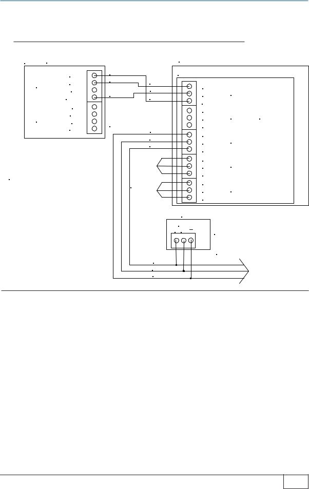
Integrated TS-TPI / TS-LS300 with Automatic Tank Gauge TS-1001, TS2001
ATG TS1001 OR TS2001 ONLY |
LS300 |
|
485A |
RED |
|
TPI BOARD |
|
|
|
|
|
|
|
TS-LLD |
485B |
BLACK |
BLACK |
|
|
|
TXD 485- |
|
|||
|
DSY |
WHITE |
WHITE |
GND |
HOST PORT |
|
S,RTN |
RED |
|||
|
|
RXD 485+ |
|
||
|
IN 1 |
|
|
|
|
|
CABLE-BELDEN |
|
TXD 485- |
PORT 1 |
|
|
GND |
|
|||
INPUTS |
CONDUCTOR |
|
GND |
||
IN 2 |
#9365-18AWG |
|
RXD 485+ |
|
|
|
GND |
OR EQUIVALENT |
|
|
|
|
|
TXD 485- |
|
||
|
|
|
|
PORT 2 |
|
|
|
|
|
GND |
|
SEE TANK SENTINEL INSTALLATION GUIDE |
|
RXD 485+ |
|
||
|
TXD 485- |
|
|||
(PART # 000-1050) AND LS300 USER'S GUIDE |
|
PORT 3 |
|||
|
GND |
||||
(PART # 000-0040) FOR COMPLETE ATG AND |
|
||||
LS300 WIRING INFORMATION |
|
|
RXD 485+ |
|
|
|
|
|
|
TXD 485- |
PORT 4 |
|
|
|
|
GND |
|
|
|
|
|
RXD 485+ |
|
Figure 2-1
●This application provides communication between ATG and TS-LS300 only. The Line Leak detector option is required on the ATG for operation.
●See Tank Sentinel Installation Guide and TS-L300 AutoLearn Installation Guide for specific instructions for each component
2 |
Page 2-2 |
Installation and Wiring |
TS-TPI Installation and Wiring Guide
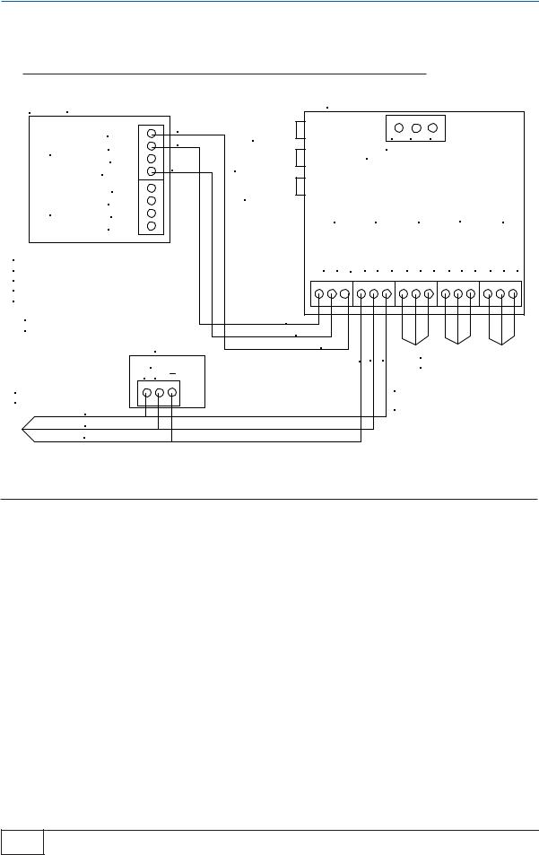
Integrated TS-TPI / TS-LS300 to Automatic Tank Gauge TS-1001, TS2001 and TPCs
ATG TS1001 OR TS2001 ONLY |
|
|
||
|
485A |
RED |
|
|
|
BLACK |
BLACK |
||
TS-LLD |
485B |
|||
|
||||
|
DSY |
WHITE |
WHITE |
|
|
S,RTN |
RED |
||
|
|
|||
|
IN 1 |
CABLE-BELDEN |
|
|
INPUTS |
GND |
CONDUCTOR |
|
|
IN 2 |
#9365-18AWG |
|
||
|
|
OR EQUIVALENT |
|
|
GND |
BLACK |
|
|
||
|
WHITE |
|
|
RED |
|
SEE TANK SENTINEL INSTALLATION GUIDE |
|
|
(PART # 000-150), LS300 USER'S GUIDE |
|
|
(PART # 000-0040), AND APPROPRIATE |
|
|
TPC INSTALLATION AND OWNER'S MANUAL |
ADDITIONAL |
|
FOR COMPLETE WIRING INFORMATION |
||
TPC |
||
|
GROUPS |
RED
WHITE
BLACK
LS300
TPI BOARD
TXD 485- |
HOST PORT |
|
GND |
|
|
RXD 485+ |
|
|
TXD 485- |
PORT 1 NOT USED |
|
GND |
|
|
RXD 485+ |
|
|
TXD 485- |
PORT 2 |
|
GND |
|
|
RXD 485+ |
|
|
TXD 485- |
PORT 3 |
|
GND |
|
|
RXD 485+ |
|
|
TXD 485- |
PORT 4 |
|
GND |
|
|
RXD 485+ |
|
|
TPC |
CONTROLLERS MAY INCLUDE THE |
|
RS485 |
||
|
MagVFC, STP-SCI, STP-SCIII, |
|
+ G |
IST-VFC, AND STP-SC |
|
|
|
ADDITIONAL TPC CONNECTIONS |
Figure 2-2
●This application provides communication between ATG, TS-LS300, and TPCs. The Line Leak detector option is required on the ATG for full communication with TS-
LS300.
●See Tank Sentinel Installation Guide and TS-L300 AutoLearn Installation Guide for specific instructions for each component
●Connect TPCs so all Stand alone TPCs are on the same port and Master/Slave configured units are on their own port. Address TPCs so controllers on same port have unique addresses. If similar type stand alone TPCs are installed on the same port as Master/Slave TPCs the stand alone TPCs will be seen as Slave units.
Installation and Wiring |
Page 2-3 |
2 |
TS-TPI Installation and Wiring Guide

TS-TPI / two TS-LS300 with Automatic Tank Gauge TS-1001, TS2001
ATG TS1001 OR TS2001 ONLY |
|
|
||
|
485A |
RED |
|
|
|
BLACK |
|
||
TS-LLD |
485B |
BLACK |
||
|
||||
|
DSY |
WHITE |
WHITE |
|
|
S,RTN |
RED |
||
|
|
|||
|
IN 1 |
CABLE-BELDEN |
||
|
GND |
|||
INPUTS |
3 CONDUCTOR |
|||
IN 2 |
#9365-18AWG |
|
||
|
GND |
OR EQUIVALENT |
||
SEE TANK SENTINEL INSTALLATION GUIDE (PART # 000-1050) AND LS300 USER'S GUIDE (PART # 000-0040) FOR COMPLETE ATG AND LS300 WIRING INFORMATION
LS300
TPI BOARD
TXD 485- |
HOST PORT |
GND |
|
RXD 485+ |
|
TXD 485- |
PORT 1 |
GND |
|
RXD 485+ |
|
TXD 485- |
PORT 2 |
GND |
|
RXD 485+ |
|
TXD 485- |
PORT 3 |
GND |
|
RXD 485+ |
|
TXD 485- |
PORT 4 |
GND |
|
RXD 485+ |
|
PURCHASE |
LS300 |
RS232 CABLE |
|
LOCALLY |
|
EXTERNAL
RS232 PORT
NO TS-TPI BOARD IN THIS LS300
IF TS-TPI IS PRESENT, REMOVE IT BEFORE
MAKING THE RS232 CONNECTION
Figure 2-3
●Provides communication between ATG and both TS-LS300 consoles. ATG requires the Line Leak detection option for full operation of TS-LS300 and ATG communication.
●Only one TS-LS300 has TS-TPI installed, if both have a TPI board remove the TPI from one of the TS-LS300
●The RS232 cable is supplied by the customer
●TS-TPI configuration switch SW1 pole 3 is ON. See Figure 2-7 for more details and switch settings on TS-TPI
2 |
Page 2-4 |
Installation and Wiring |
TS-TPI Installation and Wiring Guide
Wire diagram for TS-TPI with two TS-300 AutoLearn to Automatic Tank Gauge TS-1001, TS2001 and TPCs
ATG TS1001 OR TS2001 ONLY |
|
|
LS300 |
|
||
|
485A |
RED |
|
TPI BOARD |
|
|
|
|
|
|
|
||
TS-LLD |
485B |
BLACK |
BLACK |
|
|
|
|
TXD 485- |
|
||||
|
DSY |
WHITE |
WHITE |
HOST PORT |
||
S,RTN |
RED |
GND |
||||
|
RXD 485+ |
|
||||
|
IN 1 |
CABLE-BELDEN |
|
|||
|
TXD 485- |
|
||||
|
GND |
|
||||
INPUTS |
3 CONDUCTOR |
PORT 1 |
||||
GND |
||||||
IN 2 |
#9365-18AWG |
|
||||
|
GND |
OR EQUIVALENT |
RXD 485+ |
|
||
|
|
|
|
TXD 485- |
PORT 2 |
|
SEE TANK SENTINEL INSTALLATION GUIDE |
|
GND |
||||
(PART # 000-1050) AND LS300 USER'S GUIDE |
|
RXD 485+ |
|
|||
(PART # 000-0040) FOR COMPLETE ATG AND |
|
TXD 485- |
|
|||
LS300 WIRING INFORMATION |
|
|
PORT 3 |
|||
|
|
GND |
||||
|
|
|
|
|||
|
|
|
ADDITIONAL |
RXD 485+ |
|
|
|
|
|
TXD 485- |
|
||
|
|
|
|
PORT 4 |
||
|
|
|
TPC |
GND |
||
|
|
|
GROUPS |
RXD 485+ |
|
|
TPC |
|
|
|
LS300 |
|
|
RS485 |
|
|
|
|
|
|
+ G |
|
|
|
|
|
|
|
BLACK |
|
|
|
|
|
|
WHITE |
|
|
|
|
|
|
RED |
|
|
|
|
|
CONTROLLERS MAY INCLUDE THE |
|
|
|
|
||
MagVFC, STP-SCI, STP-SCIII, VFC AND STP-SC |
|
|
|
|||
PURCHASE
RS232 CABLE
LOCALLY EXTERNAL
RS232 PORT
NO TS-TPI BOARD IN THIS
TS-LS300 CONSOLE. IF TS-TPI
IS PRESENT REMOVE IT BEFORE
MAKING RS232 CONNECTIONS
Figure 2-4
●Provides communication between ATG, TPCs, and both TS-LS300 consoles. ATG requires the Line Leak detection option for full operation of TS-LS300 and ATG communication.
●Only one TS-LS300 has TS-TPI installed, if both have a TPI board remove the TPI from one of the TS-LS300
●The RS232 cable is supplied by the customer
●Connect TPCs so all Stand alone TPCs are on the same port and Master/Slave configured units are on their own port. Address TPCs so controllers on same port have unique addresses. If similar type stand alone TPCs are installed on the same port as Master/Slave TPCs the stand alone TPCs will be seen as Slave units.
●TS-TPI configuration switch SW1 pole 3 is ON. See Figure 2-7 for more details and switch settings on TS-TPI
Installation and Wiring |
Page 2-5 |
2 |
TS-TPI Installation and Wiring Guide
Stand AloneTS-TPI with Automatic Tank Gauge TS-1001 or TS2001 and TPCs
ATG TS1001 OR TS2001 ONLY
|
485A |
RED |
|
|
BLACK |
||
TS-LLD |
485B |
||
|
|||
|
DSY |
WHITE |
|
|
S,RTN |
||
|
|
||
|
IN 1 |
|
|
INPUTS |
GND |
|
|
IN 2 |
|
||
|
GND |
|
SEE TANK SENTINEL INSTALLATION GUIDE (PART # 000-1050), THIS TPI USER'S GUIDE AND APPROPRIATE
TPC INSTALLATION AND OWNER'S MANUAL FOR COMPLETE WIRING INFORMATION
CABLE-BELDEN CONDUCTOR #9365-18AWG OR EQUIVALENT
TPC
RS485 + G
ADDITIONAL
TPC CONNECTIONS RED WHITE BLACK
STAND ALONE TPI
TS-TPI |
|
|
|
|
|
|
RESET |
|
|
GND L2/N |
L1 |
|
|
TPC FAULT |
PORT |
1 |
INPUT POWER |
4 |
||
2 |
3 |
|||||
|
120 -240 Vac 50/60 hz |
|
||||
RESET |
|
|
|
|
|
|
ALARM |
HOST |
PORT |
PORT |
PORT |
PORT |
|
SILENCE |
||||||
|
|
|
|
|
||
|
TXD 485GND RXD 485+ |
TXD 485GND |
RXD 485+ TXD 485GND |
RXD 485+ TXD 485GND RXD 485+ |
TXD 485GND RXD 485+ |
|
BLACK |
|
|
|
|
||
|
WHITE |
BLACK WHITE RED |
ADDITIONAL TPC |
|||
|
RED |
|||||
|
|
|
|
|
||
GROUPS
CONTROLLERS MAY INCLUDE THE
MagVFC, STP-SCI, STP-SCIII, VFC
AND STP-SC
Figure 2-5
●Communication between ATG and TPCs, no additional ATG options required for full operation
●Stand Alone TS-TPI requires separate 120 - 240 vac, 50/60 hz, power
●See Tank Sentinel Installation Guide for specific ATG instructions
●TPCs that can be installed are MagVFC, IST-VFC, STP-SCI, STP-SC and STPSCIII. Available functions are limited on the IST-VFC, STP-SC and the STP-SCIII controllers, see troubleshooting section for details
●Connect TPCs so all Stand alone TPCs are on the same port and Master/Slave configured units are on their own port. Address TPCs so controllers on same port have unique addresses. If similar type stand alone TPCs are installed on the same port as Master/Slave TPCs the stand alone TPCs will be seen as Slave units.
2 |
Page 2-6 |
Installation and Wiring |
TS-TPI Installation and Wiring Guide
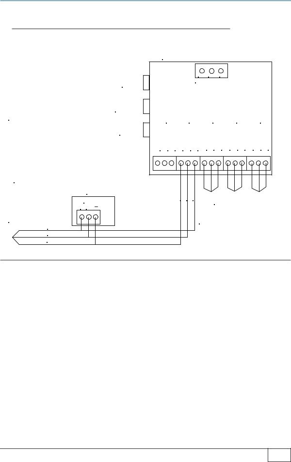
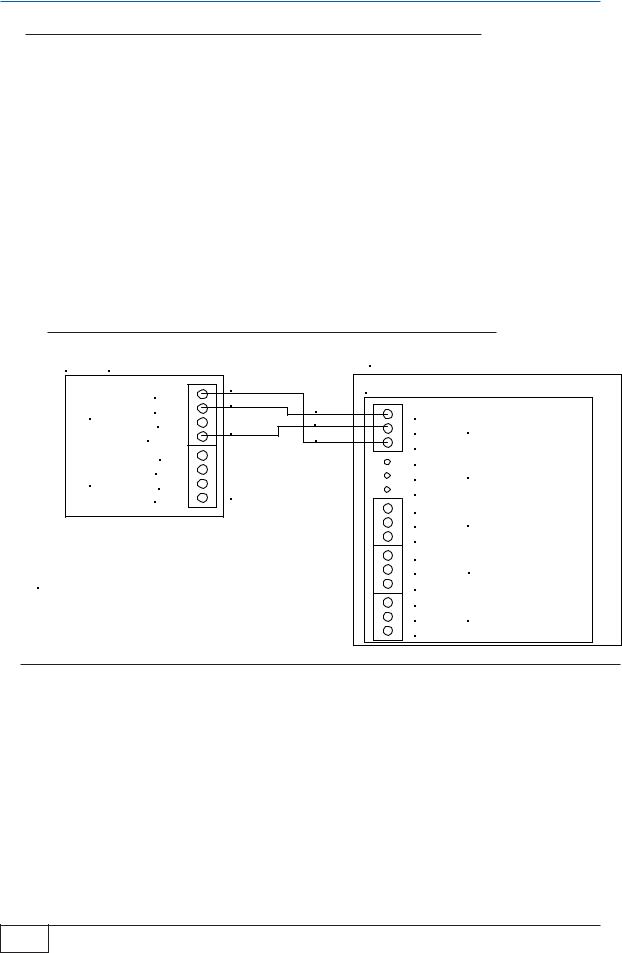
Stand AloneTS-TPI with TPCs
SPECIFICATIONS Input power:
120 - 240 Vac 50/60 hz
Indoor installation only. Operating temperature: 40 - 105° F (4 - 41° C)
CABLE-BELDEN CONDUCTOR
#9365-18AWG OR EQUIVALENT
TPC
RS485 + G
ADDITIONAL
TPC CONNECTIONS RED WHITE BLACK
TS-TPI
RESET
TPC FAULT RESET
ALARM SILENCE
STAND ALONE TS-TPI
|
|
GND L2/N |
L1 |
|
HOST PORT |
|
INPUT POWER |
|
|
PORT 1 |
PORT 2 |
PORT 3 |
PORT 4 |
|
TXD 485GND RXD 485+ |
TXD 485GND |
RXD 485+ TXD 485GND |
RXD 485+ TXD 485GND RXD 485+ |
TXD 485GND RXD 485+ |
BLACK WHITE RED |
ADDITIONAL TPC |
|
GROUPS |
CONTROLLERS MAY INCLUDE THE
MagVFC, STP-SCI, STP-SCIII, IST-VFC
AND STP-SC
Figure 2-6
●Communication between TS-TPI and TPCs. Use this application for remote controller fault indication and controller fault reset.
●Stand Alone TS-TPI requires separate 120 - 240 vac, 50/60 hz, power
●TS-TPI reset switch will reset the TS-TPI in the event of a communication conflict.
●The TPC fault reset will reset a pump controller that is in a fault conditon. It will only reset controllers that are indicating a fault alarm. If none of the controllers are in alarm no reset will take place.
●Alarm Silence button will silence the audible alarm but not clear the fault.
●Connect TPCs so all Stand alone TPCs are on the same port and Master/Slave configured units are on their own port. Address TPCs so controllers on same port have unique addresses.
Installation and Wiring |
Page 2-7 |
2 |
TS-TPI Installation and Wiring Guide

TPI Configuration Switch
Locate the single dip switch on the TS-TPI board labeled SW1.
This set of switches sets how the various ports communicate. The host (ATG) and Pump Controllers all communicate using RS-485 connections. The TS-LS300 communicates using RS232.
The Factory default setting is switches 1, 2 and 3 are OFF and switch 4 is ON. When a second TSLS300 is used (more than 4 pipelines at a site) switch 3 is set to the ON positon, see Figure 2-7
|
SW1 |
Stand Alone TS-TPI |
TS-TPI in TS-LS300 |
Two TS-LS300 in use |
|
1 |
OFF |
OFF |
OFF |
|
2 |
OFF |
OFF |
OFF |
|
3 |
OFF |
OFF |
ON |
|
4 |
ON |
ON |
ON |
Figure 2-7
2 |
Page 2-8 |
Installation and Wiring |
TS-TPI Installation and Wiring Guide

3TANK SENTINEL/TS-TPI INTERFACE
Overview
The Turbine Pump Interface (TS-TPI) hardware has been developed to facilitate communications of the Turbine Pump Controllers (TPC) operating conditions with the INCON Tank Sentinel Automatic Tank Gauge (ATG) consoles via the RS-485 port.
The integration of ATG, TS-TPI and TPC allows the ATG to intervene when pumps experience certain fault conditions by resolving the fault and enabling the pump to continue dispensing fuel. In addition to this, the ATG keeps an alarm history to aid in troubleshooting. A technician can review an alarm history report at the site or remotely via System Sentinel® and System Sentinel Anyware® .
The TS-TPI requests status and fault conditions of the TPCs. This information is transmitted to the ATG on demand. The ATG can then make this status available for purposes of:
●Displaying, Printing and Faxing Pump Controller Status
●Resetting Pump Controllers
●Making Pump Controller Status available to System Sentinel® and System Sentinel Anyware®
●Basic Operation Features
There are several basic operation features listed below and detailed further in separate chapters of this manual.
Monitor, Record and Reset Pump Controller Faults
The primary feature is that the ATG maintains the state of the Pump controller such that it continues to run and function without user intervention. The Pump Controller will stop a pump when a fault condition exists. The ATG monitors pump controllers through the RS-485 port for fault conditions. When fault conditions are received, the ATG will manage them by reporting alarms, silencing the audible alarms on the controllers, and resetting the controller when appropriate.
Fault Diagnostic Capabilities
The secondary feature provides fault detection diagnostics. The ATG will take control of the pumps when certain fault conditions are active in the ATG. For example, if a site has multiple tanks of the same product and one of the tanks gets overfilled, the ATG will make the over filled tank the priority tank, even if it is not programmed as the priority tank, until the over fill conditon is corrected. Pump Controller alarms have been added to the alarm processing code of the tank gauge.
Level Management
The third feature allows a customer to utilize the ATG to control the “mode” the pumps use to draw down product in two or more tanks with the same product. The “Leveling Mode” alternates the pumps so that the tank levels are equal as the tanks are being drawn down. The “Priority Mode” gives one pump priority over the others while it draws product down. A pump remains in “Priority Mode” until an user specified reserve percentage level is reached. The tank gauge then gives priority to another pump and it then draws down the product from another tank.
TANK SENTINEL/ TS-TPI INTERFACE |
Page 3-1 |
3 |
TS-TPI Installation and Wiring Guide |
|
|
|
|
 Loading...