


Submersible Well Pump
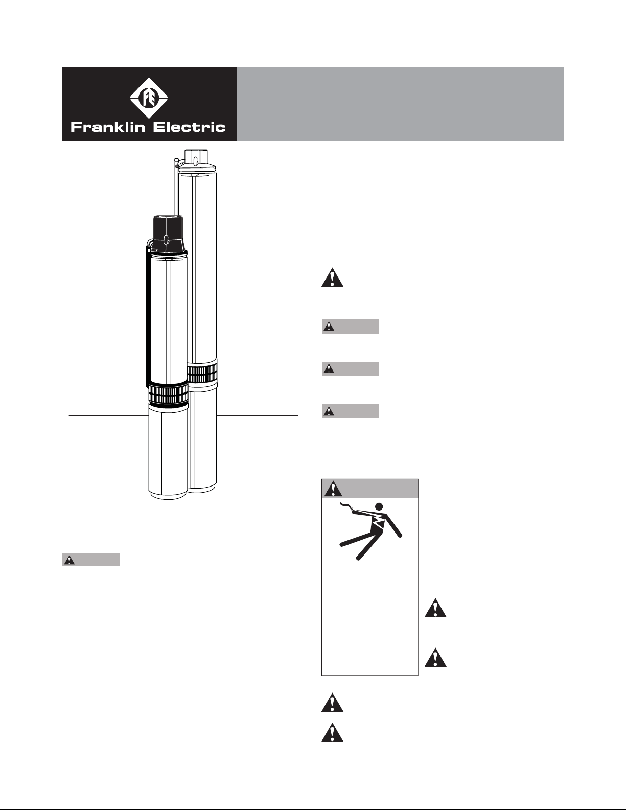
4” and 6”
SUBMERSIBLE PUMPS
OWNER'S MANUAL
All 4” models willl include either a built-in or external
mounted check valve with the discharge head. 6”
models do not include a check valve, and will need to be
purchased separately. Example: Franklin Control Box for
Franklin motors. Make certain that your available voltage
corresponds to that of your motor.
READ AND FOLLOW SAFETY INSTRUCTIONS
This is the safety alert symbol. When you see
this symbol on your pump or in this manual, look
for one of the following signal words and be alert to the
potential for personal injury:
BEFORE INSTALLING PUMP, BE SURE TO READ
THIS OWNER’S MANUAL CAREFULLY.
CAUTION
or pump will be damaged. The motor on this pump
is guaranteed by the manufacturer and in event of
failure it must be returned to an authorized service
station for repairs. Motor warranty is void if repairs
aren’t made by an authorized repair station.
Fill pump with water before starting
INSPECT THE SHIPMENT
Examine the pump when it is received to be sure there
has been no damage in shipping. Should any be evident,
report it immediately to the dealer from whom the pump
was purchased. Please check the pump package to see
that it includes pump, motor, and motor leads (if your
pump purchase includes a motor).
DANGER
serious personal injury, death or major property damage
if ignored.
WARNING
serious personal injury, death or major property damage
if ignored.
CAUTION
cause minor personal injury or major property damage if
ignored.
The label NOTICE indicates special instructions, which
are important but not related to hazards.
WARNING
Hazardous voltage.
Can shock, burn, or
cause death.
Ground pump before
connecting to power
supply. Disconnect
power before working
on pump, motor
or tank.
Meet National Electrical Code, Canadian Electrical
Code, and local codes for all wiring.
Follow wiring instructions in this manual when
connecting motor to power lines.
warns about hazards that will cause
warns about hazards that can cause
warns about hazards that will or can
Carefully read and follow all
safety instructions in this
manual and on pump.
Keep safety labels in good
condition.
Replace missing or damaged
safety labels.
Wire motor for correct
voltage. See “Electrical”
section of this manual and
motor nameplate.
Ground motor before
connecting to power supply.
ATTENTION!
IMPORTANT INFORMATION FOR
INSTALLERS OF THIS EQUIPMENT!
THIS EQUIPMENT IS INTENDED FOR
INSTALLATION BY TECHNICALLY QUALIFIED
PERSONNEL. FAILURE TO INSTALL IT IN
COMPLIANCE WITH NATIONAL AND LOCAL
ELECTRICAL CODES, AND WITH FRANKLIN
ELECTRIC RECOMMENDATIONS, MAY RESULT
IN ELECTRICAL SHOCK OR FIRE HAZARD,
UNSATISFACTORY PERFORMANCE, AND
EQUIPMENT FAILURE. FRANKLIN INSTALLATION
INFORMATION IS AVAILABLE FROM PUMP
MANUFACTURERS AND DISTRIBUTORS, AND
DIRECTLY FROM FRANKLIN ELECTRIC. CALL
FRANKLIN TOLL FREE 800-348-2420 FOR
INFORMATION. RETAIN THIS INFORMATION
SHEET WITH THE EQUIPMENT FOR
FUTURE REFERENCE.
WARNING
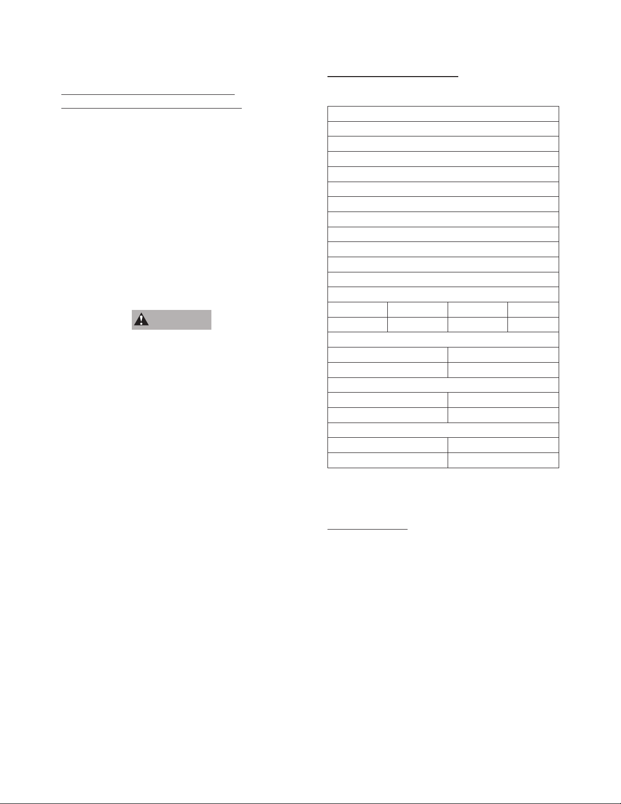
INSTALLATION RECORDS
It is good idea to keep an accurate record of your
installation. Be sure to record the data below:
Purchased From:
Date of Installation:
Pump Model No.*
Pump Date Code*
Well Inside Dia.(in/mm):
Depth of Well(ft/m):
Depth of Water(ft/m):
Pump Setting(ft/m):
Drop Pipe Size:
Wire Size(pump to control box):
Wire Size(control box to power source):
Horizontal Offset(between well & house):
Make of Motor*
Amps HP Volts Ph
SERIOUS OR FATAL ELECTRICAL SHOCK MAY
RESULT FROM FAILURE TO CONNECT THE
MOTOR, CONTROL ENCLOSURES, METAL
PLUMBING, AND ALL OTHER METAL NEAR THE
MOTOR OR CABLE, TO THE POWER SUPPLY
GROUND TERMINAL USING WIRE NO SMALLER
THAN MOTOR CABLE WIRES. TO REDUCE
RISK OF ELECTRICAL SHOCK, DISCONNECT
POWER BEFORE WORKING ON OR AROUND
THE WATER SYSTEM. DO NOT USE MOTOR IN
SWIMMING AREAS.
Make of Control Box
HP Volts
Power Supply
Volts HZ
Pressure Switch (PSI)
Cut-in Cut-out
* This Information is on your pump or motor tag. It will
help us identify your pump in case of later inquiries.
TEST RUNNING
If test running pump before installation:
1. Insure that the power supply corresponds with that
shown on the nameplate of the motor and control
box. (if required).
2. Install pump and components appropriate for the
test as shown in Fig. 1.
3. Make sure power supply is turned off and circuit
breaker or disconnect switch is open. Make
electrical connections appropriate to your motor as
shown in Fig. 2, 3 or 4.
4. THREE PHASE UNIT - A three phase motor
requires a magnetic starter equipped with quick-trip,
ambient compensated heaters of correct size for the
horsepower of the motor.
To insure correct rotation of three phase units, brace
pump shell securely and apply power momentarily
by snapping line switch quickly on and off. If rotation
is correct, reaction of the shell will be clockwise
when viewed from pump discharge (that is, pump
shaft will rotate counter clockwise). Interchange any
two leads at magnetic starter to reverse rotation.
5. Run pump and motor unit for a few seconds to
ensure that it is in working order.
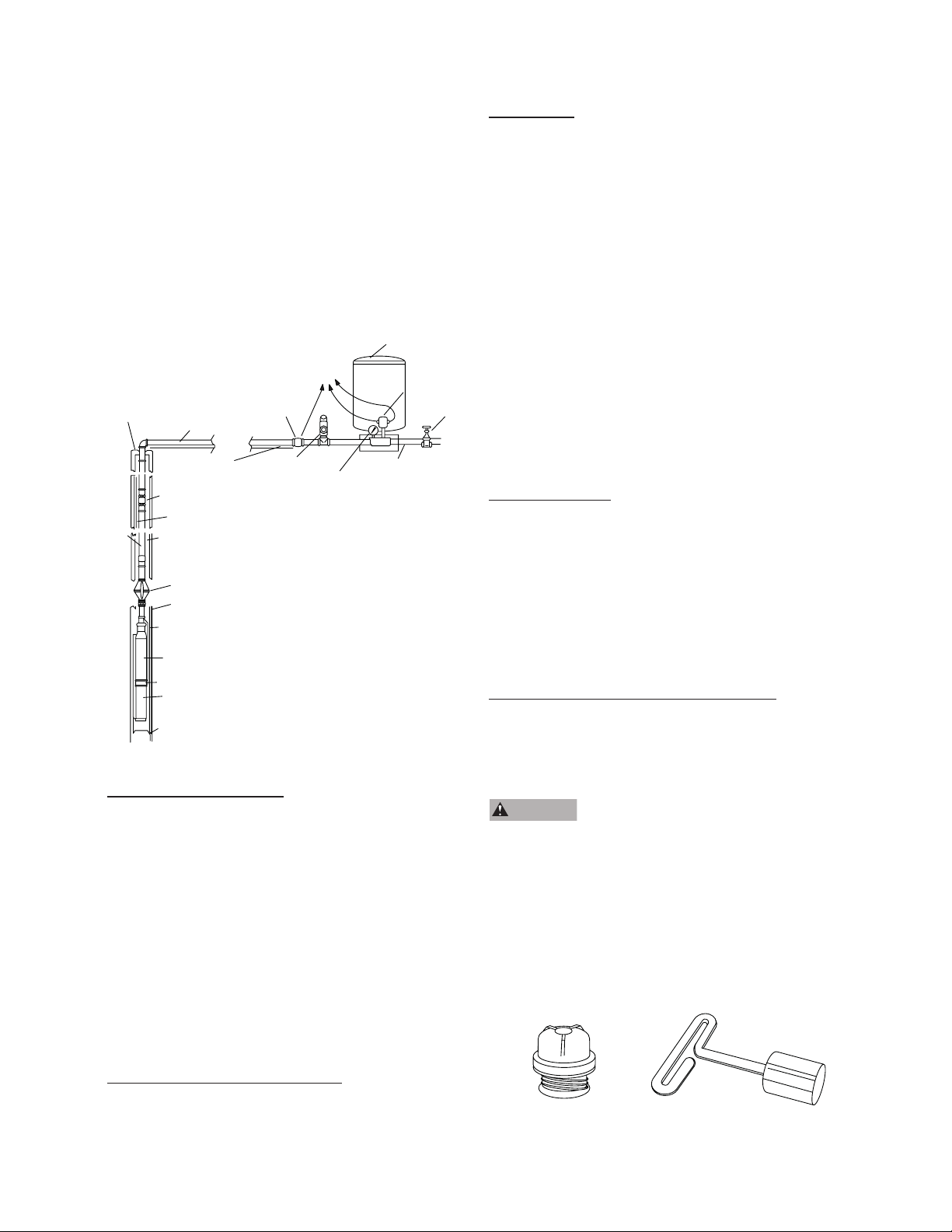
FIGURE 1 - Installation Diagram
Pressure Tank
Sanitary Well Seal
or Pitless Adapter
Drop Pipe
Discharge Pipe
Submersible Cable
Spring-Loaded
Check Valve
(Recommended every 100’/30m)
Safety Cable
Cable
(secured to drop
pipe with tape or
clamps every 10’/3m)
Torque Arrestor
Well Casing
Spring-Loaded
Check Valve
at Pump Discharge
Submersible
Pump Unit
Suction Screen
Motor
Well Screen or
Casing Perforations
See Wiring Diagrams
Spring-Loaded
Check Valve
Pressure Relief Valve
Note: Keep pump at least 5’ from
bottom of well and above well screen
or casing perforations.
Pressure Gauge
Pressure Switch
Service Pipe
SUITABILITY OF WELL
Install the pump only in a well that has been properly
developed. Water from an undeveloped well often
contains an excessive amount of sand, dirt, and
abrasives which can damage the pump. Check that
the well is large enough to allow the pump to be set
at the required depth. Don’t set the pump below the
casing perforations or well screen unless you make
arrangements to ensure an adequate fl ow of water
over the motor for cooling purposes. Determine the
correct pump setting from the driller’s record by taking
into account the static water level and the drawdown
at the proposed pumping rate. Keep the pump at least
fi ve feet from the bottom of a drilled well.
Gate Valve
DROP PIPE
Galvanized pipe is recommended for suspending
submersible pumps into the well. Plastic pipe may
be used only when observing the plastic pipe
manufacturer’s recommendations of depth and pressure.
Give special consideration to:
1. A safety cable to prevent loss of pump if pipe should
break.
2. Torque arrestor just above pump to prevent chafi ng
the cable when pump and pipe twist during the starting
and stopping cycle. (See Figure 1)
Schedule 40 galvanized pipe is suitable for settings to
600 feet(180m). For deeper settings, use schedule 40
pipe for the bottom 600 feet(180m), and schedule 80 for
the remainder.
Take great care to keep pipes clean and free from
pebbles, scale and thread chips. Make sound, air-tight
connections at all fi ttings. Pipe sealant is recommended.
CHECK VALVES
Many pumps have a built-in or externally supplied check
valve. For a pump without one, install a check valve
immediately above the pump. Install an additional check
valve above the ground. If the pump is more than 100
feet (30m) below the wellhead, install another check
valve in the drop pipe 100 feet (30m) above it. For pump
settings deeper than 200 feet (60m), install additional
check valves at intervals of 100 feet (30m).
REMOVABLE POPPET CHECK VALVE
4” submersible pumps with a 1-1/4” discharge are
supplied with a spring-loaded REMOVABLE poppet style
check valve assembly. The check valve can be removed
from the pump discharge when the pump is installed in
applications where drain back is desired.
WARNING
can cause the pump to rotate backwards. If pump/
motor starts during this time; damage to the pump
can occur.
The check valve can be removed with the use of the
T-Handle Poppet Wrench(part no. 23498207). Ordered
separately. Or, with standard needle nose pliers. The
poppet assembly is left hand threaded and is removed
by turning CLOCKWISE.
If reinstalling a Popppet Check Valve assembly, the
assembly should be tightened to 15 inch-pounds.
Fluid draining back through the pump
SPLICING THE POWER CABLE
Follow the instructions enclosed in the cable splicing
kit you purchase.
Poppet Assembly
T-Handle Poppet Wrench
1
INSTALLATION OF PUMP, DROP PIPE, AND
ASSOCIATED EQUIPMENT
Fig. 1 illustrates a typical well installation showing in
ground components. Adhere to the following items when
installing the pump and drop pipe:
1. Fasten the submersible cable to the drop pipe with
clamps or appropriate tape every 10 ft. (3m) to
prevent tangling and damage to the cable. The cable
must remain slack when using plastic drop pipe to
allow for stretching of pipe when installed in the well.
2. Take care not to scrape or pinch the submersible
cable against the well casing.
3. Use an ohmmeter or megger to make insulation and
continuity checks on the cable once the pump is
installed. This locates any fault in the cable.
4. Make sure a check valve is installed immediately
above the pump. Install additional check valves at
100’ (30m) intervals.
5. Install a torque arrestor just above the pump to
prevent chafi ng the cable when pump anad pipe twist
during starting and stopping.
6. Attach a safety cable to pump to prevent loss of pump
if pipe should break.
7. Place a sanitary well seal or pitless adapter with
an approved cover plate over top of well per
manufacturers recommendations.
8. Keep pump at least 5’ (1.5m) from bottom of well and
above well screen or casing perforations.
ELECTRICAL INFORMATION
1. Employ a licensed electrician to perform the wiring.
All wiring must be done in accordance with applicable
national and local electrical codes.
2. Check that the power supply corresponds with the
electrical rating of the submersible motor and the
control box(if required). Make sure that the control box
electrical rating matches the motor electrical rating.
3. Every installation requires a fused disconnect switch
or circuit breaker.
4. Every installation must be grounded. There must be
a reliable ground connection between the pump and
the distribution panel. The motor lead incorporates a
green grounding conductor.
5. Lightning arrestors are recommended for every
installation. All stainless steel, single phase motors
thru 5HP have built-in lightning arrestors. Any 6”
motor or 4”, 3-phase motor requires a separate
lightning arrestor installed as close to the wellhead
as possible. Install the arrestor in accordance with
manufacturers recommendations. A lightning arrestor
provides protection against induced voltage surges on
secondary power lines; it is not effective against direct
hits.
6. Mount the control box in an area protected from rain,
snow, direct sunlight or other high temperatures as
this may cause tripping of the overload protector.
Also protect the control box from extreme cold (below
o
25
F/-32oC) as this may have adverse effects on
starting capacitor.
7. A two-wire pump does not require a motor control box,
since all electrical components are built inside the
motor. Fig. 2 shows a typical wiring diagram for a twowire installation.
FIGURE 2 - 2 WIRE, 1 Phase, 1/3 thru 1-1/2 HP
Pump Wiring Diagram
Circuit Breaker or
Fuse Disconnect Switch
Pressure Switch
Incoming 1 Phase Power
1 Phase Submersible Motor
Submersible Cable
8. A three-wire, single-phase pump requires a motor
control box incorporating overload relays. Fig. 3
shows a typical wiring diagram for a three-wire, singlephase installation. Note that a magnetic contactor
must be used if the pressure switch electrical rating
is not suffi cient to handle the submersible motor
electrical rating. The pressure switch would then be
incorporated into a pilot circuit to control the magnetic
contactor. Make the connections at the control box in
accordance with the wiring diagram in the control box
to avoid damage to the motor.
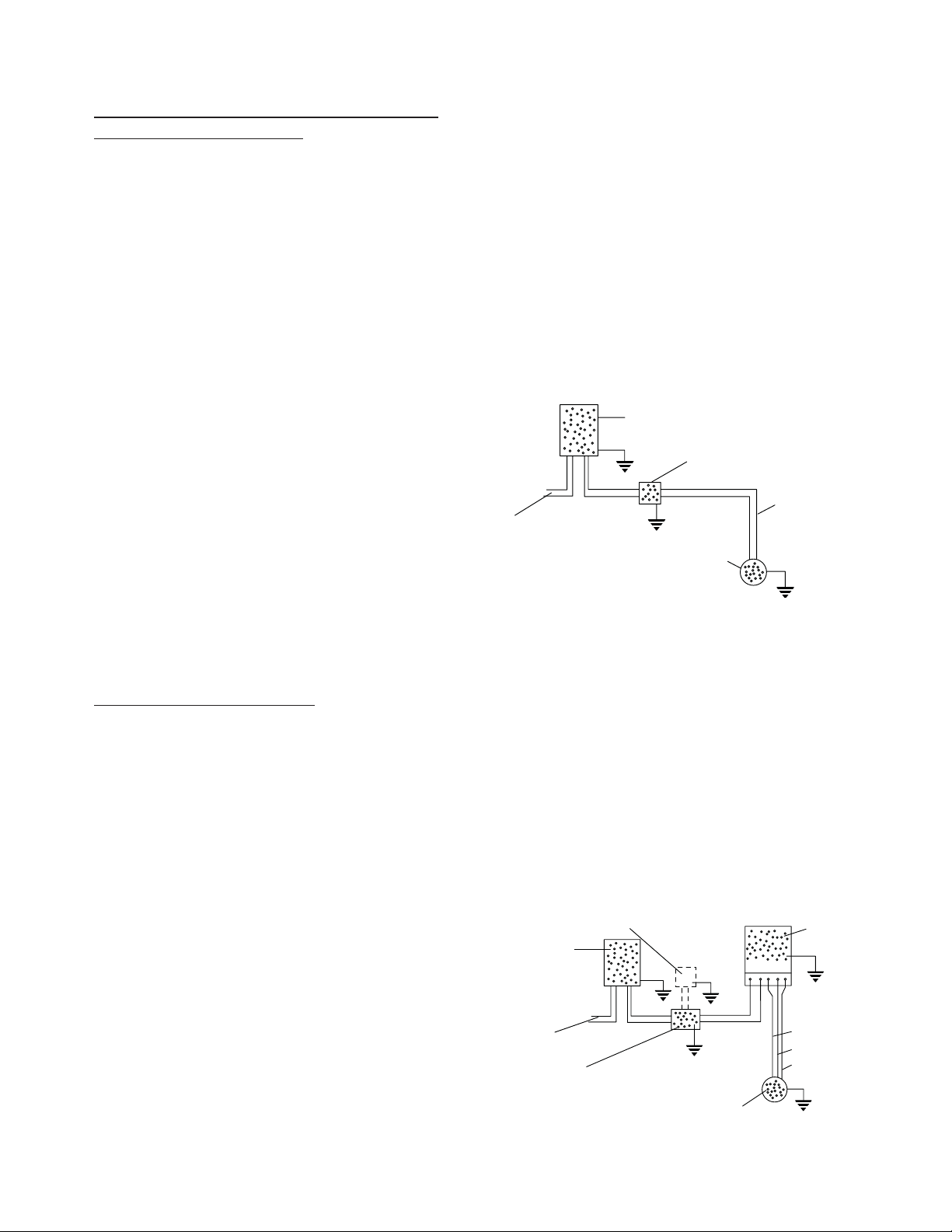
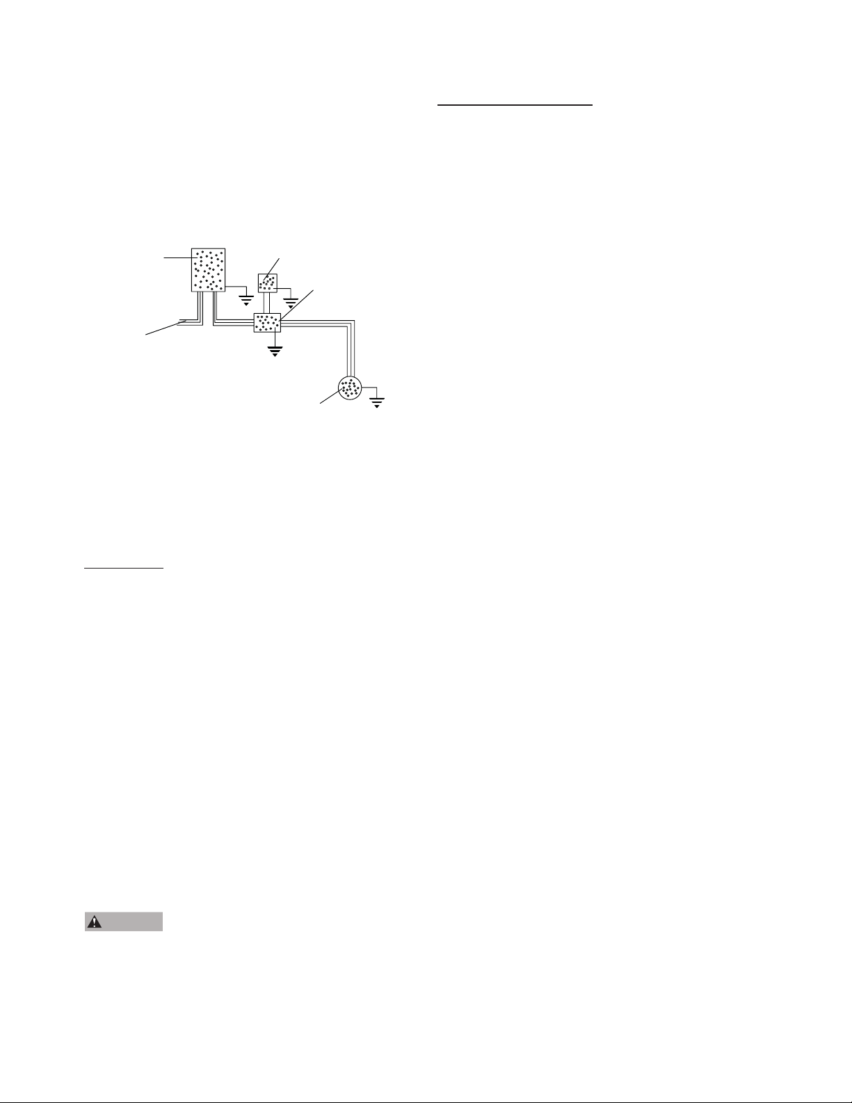
FIGURE 3 - 3-WIRE, 1 Phase, 1/3 thru 15 HP
Pump Wiring Diagram
Note: Order of red, yellow and black may
Pressure Switch (for pilot circuit)
If Magnetic Contactor is used
for starting.
Circuit Breaker
or Fused Disconnect Switch
Incoming 1 Phase Power
Pressure Switch (for direct switching) OR
Magnetic Contactor (w/ pilot circuit)
vary from control box to control box.
Always connect like colors.
L1
1 Phase Sumbersible Motor
L2 R
Y
B
Red
Yellow
Black
Single Phase
Control Box
2
9. A three-phase pump does not require a motor control
box . Fig. 4 shows a typical wiring diagram for a 3wire, three-phase installation. A magnetic contractor
with 3-leg protection having quick-trip ambient
compensated overload relays must be used.
FIGURE 4 - 3-Wire, 3 Phase, 1-1/2 thru 50 HP
Pump Wiring Diagram
Circuit Breaker OR
Fused Disconnect Switch
Incoming 3 Phase Power
Pressure Switch
Magnetic Contactor w/
3-leg protection having
quick-trip ambient
conpensated overload relays
3 Phase Submersible Motor
10. Use an ohmeter to make continuity and insulation
checks after the installation is completed.
11. Place the additional pump nameplate onto the
submersible label and place both onto disconnect
switch or circuit breaker box for future reference.
WELL TEST
Check the pump and well performance before making
the fi nal connection to the discharge system.
1. Install a gate valve on the end of the pipe. Partially
open the valve.
2. Start the pump.
3. Open valve gradually to give full fl ow.
4. If the discharge is not clear, let the pump run until
water clears. If water does not clear in 30 minutes,
stop the pump and take the necessary steps to correct
the condition. After the water has appeared clear,
check for sand by discharging into a clean bucket or
suitable container.
5. Close valve until maximum required system fl ow
rate is obtained (this should correspond to the cutin pressure of the pressure switch). Ensure that
the output of the pump at this setting is not greater
than the yield of the well. This can be checked by
monitoring the well drawdown level and ensuring tht
the level is stable at the maximum required system
fl ow rate.
CAUTION
submerged in water. If run without water, the pump
and motor could be damaged. Note also that air
drawn into the pump can cause an airlock under
certain conditions.
Never run pump unless it’s completely
LOW-YIELDING WELL
A low-yielding well exists when the output from the pump
is greater than the yield of the well. It can reduce the
water level to the suction screen so that a mixture of air
and water enters the pump. Pumping may stop since the
pump cannot generate pressure with insuffi cient water.
In this case, the column of water already in the drop pipe
holds the check valve closed and an airlock may develop
inside the pump. Because the conditions ensure neither
adequate lubrication of the pump nor proper cooling
for the motor, damage can result if power is not cut off
quickly. use one or more of the following methods to
correct and/or protect this installation.
1. Install additional length of drop pipe to place pump
lower in well if possible.
2. Install a Franklin Pumptec or similar electronic
drawdown sensor.
3. Install a fl oatless liquid level control. This device
consists of an electrical relay activated by currents
fl owing through the ground-return circuits of
electrodes hung in the well. The lower(STOP)
electrode, just above the pump, ensures that the
water level can never be pumped down to the suction
screen. The upper(START) electrode, just below
the lowest static water level, ensures that the pump
can start again as soon as the well has recovered.
A fl oatless liquid level control works in series with
the pressure switch. Refer to the manufacturers
instructions provided with control.
4. Install a fl ow control valve in the discharge line
upstream from the pressure switch. This restricts
the output from the pump without affecting the rate
that water can be drawn from the pressure tank.
Nevertheless, a heavy demand for water could
empty the pressure tank, so a tank with a bonded
diaphragm, air cell, or water bag is recommended.
5. Install a smaller pump to avoid over pumping the well.
Have dealer size pump to the well yield.
6. Install a low-pressure cut-off switch. A low pressure
cut off switch, or a pressure switch with such an
arrangement built in, protects a shallow-well pump
from losing its prime, but it does not always provide
satisfactory protection to a submersible pump from
the effects of over pumping the well. This is because
it responds to a loss of pressure at the surface,
which may occur after an air lock has formed inside
the pump. We recommend either a fl oatless liquid
level control or a fl ow control valve, in that order,
in preference to a low-pressure cutoff switch as
protection against over pumping.
3
 Loading...