

Page 1
USER INSTRUCTIONS
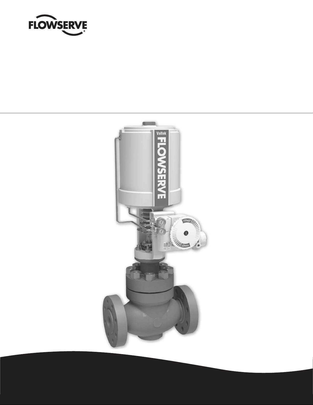
Valtek Mark 200
Globe & Angle Control Valve
FCD VLENIM0200-00 – (12/12)
Installation
Operation
Maintenance
Experience In Motion
Page 2
Mark 200 Control Valve FCD VLENIM0200– 12/12
Valtek Mark 200 High Pressure Control Valve
The Mark 200 high pressure globe control valve designed to handle the most extreme severe service applications also offers high competitive fl ow
capacity. The Mark 200’s large galleries include longer stroke lengths which provide fi ner control and result in more stages of severe service protection
in smaller size valves. With a clamped-in (DIN, screwed-in) seat ring, the Mark 200 has been designed for easy maintenance and fl exibility. The seat
retainer/cage (DIN, seat ring) in the Mark 200 can be changed out to provide an exceptional variety of severe service options, including anti-cavitation
and anti-noise.
Further sizing details are available in Performance!, Flowserve’s control valve sizing & selection software program (please contact your local Flowserve
representative for further details). The plug is typically pressure-balanced to allow smaller and more economical actuators. Flow over or under the plug
is available.
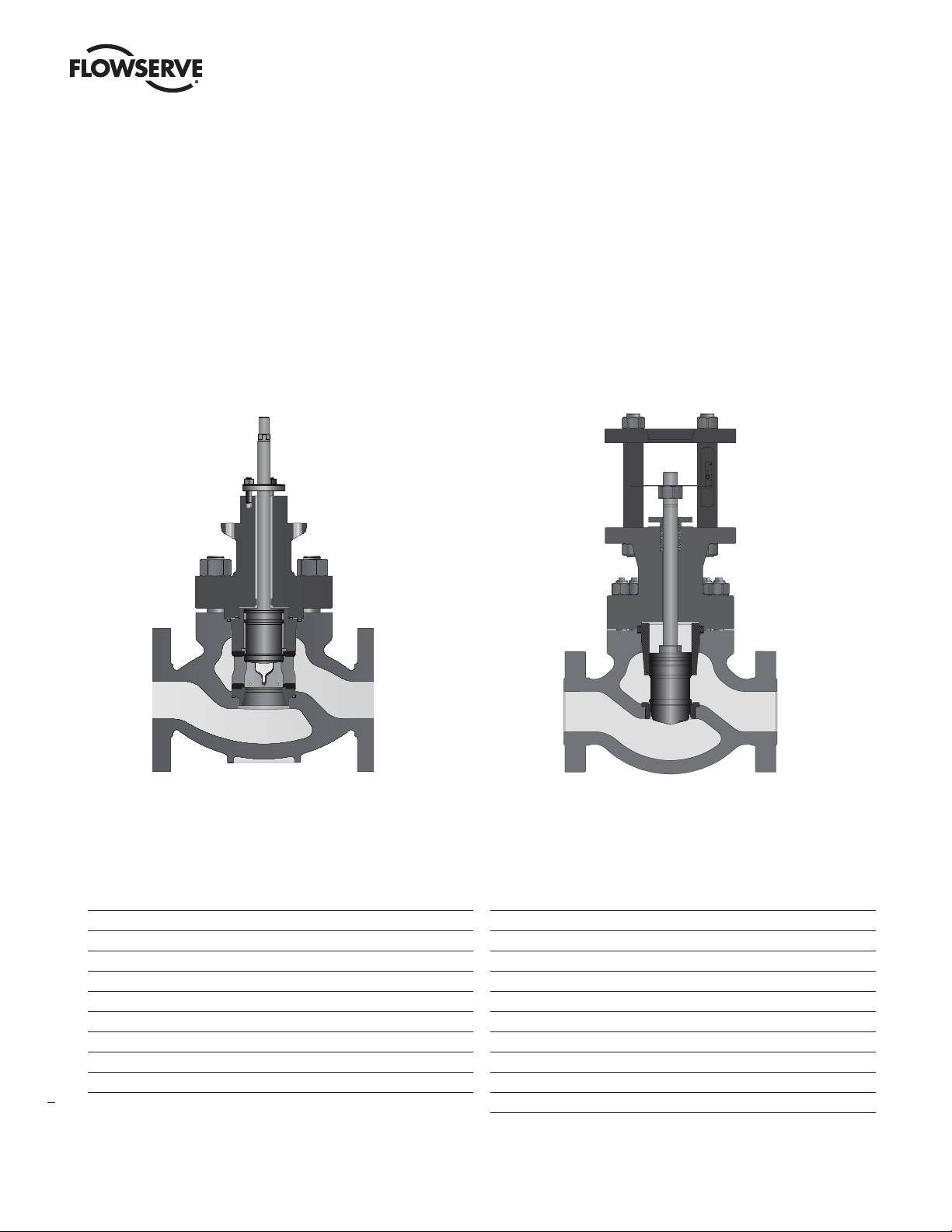
Figure 1: ASME Mark 200 Maximum Capacity Control Valve Figure 2: DIN Mark 200 Maximum Capacity Control Valve
ASME Contents
1 General Information 3
2 Terms Concerning Safety 3
3 ASME Valve Unpacking 4
4 ASME Valve Installation 4
4.1 ASME Valve Quick-check 4
5 ASME Valve Maintenance 5
ASME Valve Disassembly and Reassembly 7
6.1 Disassembling the Body 7
6.2 Reassembling the Body 8
6.3 ASME Valve Troubleshooting Chart 10
2
DIN Contents
1 General Information 3
2 Terms Concerning Safety 3
7 DIN Valve Unpacking 11
8 DIN Valve Installation 11
8.1 DIN Valve Quick-check 12
9 DIN Valve Maintenance 12
DIN Valve Disassembly and Reassembly 14
10.1 Disassembling the Body 14
10.2 Reassembling the Body 15
10.3 Special Tools 16
11 DIN Valve Troubleshooting Chart 17
Page 3

Mark 200 Control Valve FCD VLENIM0200– 12/12
1 General Information
The following instructions are designed to assist in unpacking, installing and
performing maintenance as required on Flowserve Mark 200 control valves.
Product users and maintenance personnel should thoroughly review this
bulletin prior to installing, operating or performing any maintenance on the
valve. Separate Installation, Operation, and Maintenance instructions cover
additional features (such as special trim, actuators, handwheels, packing
and positioners.)
To avoid possible injury to personnel or damage to valve parts, WARNING and
CAUTION notes must be strictly followed. Modifying this product, substituting
non-factory parts or using maintenance procedures other than outlined
could drastically affect performance and be hazardous to personnel
and equipment and may void existing warranties.
WARNING: Standard industry safety practices must be adhered
to when working on this or any other process control product.
Specifically, personal protective and lifting devices must be
used as warranted.
NOTE ON FASTENERS: Selecting the proper fastener material is the
responsibility of the customer. Typically, the supplier does not know what the
valve service conditions or environment may be. Flowserve’s standard body
bolting material is B7/2H. B8 (stainless steel) is optional for applications
more than 800°F / 425°C and with stainless steel or alloy-body valves.
The customer therefore must consider the material’s resistance to stress
corrosion cracking in addition to general corrosion. As with any mechanical
equipment, periodic inspection and maintenance is required. For more
information about fastener materials, contact your Flowserve representative.
2 Terms Concerning Safety
The safety terms DANGER, WARNING, CAUTION and NOTE are used in
these instructions to highlight particular dangers and/or to provide additional
information on aspects that may not be readily apparent.
DANGER: indicates that death, severe personal injury and/or
substantial property damage will occur if proper precautions
are not taken.
WARNING: indicates that death, severe personal injury and/ or
substantial property damage can occur if proper precautions
are not taken.
CAUTION: indicates that minor personal injury and/or property
damage can occur if proper precautions are not taken.
NOTE: indicates and provides additional technical information,
which may not be very obvious even to qualified personnel. Compliance with other, not particularly emphasized notes, with regard to
transport, assembly, operation and maintenance and with regard to
technical documentation (e.g., in the operating instructions, product
documentation or on the product itself) is essential, in order to avoid
faults, which in themselves might directly or indirectly cause severe
personal injury or property damage.
flowserve.com
3
Page 4
Mark 200 Control Valve FCD VLENIM0200– 12/12
3 ASME Valve Unpacking
1. While unpacking the valve, check the packing list against materials
received. Lists describing valve and accessories are in each shipping
container.
2. Take care to position lifting straps to avoid damage to the tubing and
mounted accessories.
WARNING: When lifting a valve using the lifting lugs, be aware
that the center of gravity may be above the lifting point. Therefore,
support must be given to prevent the actuator from rotating. Failure
to do so can cause serious injury to personnel, damage to the valve
or nearby equipment.
3. Contact your shipper immediately if there is shipping damage.
4. Should any problem arise, call your Flowserve representative.
4 ASME Valve Installation
CAUTION: The valve must be installed and commissioned by
qualified staff. Qualified staff is defined as personnel who are
familiar with the installation, commissioning and operation of
this product and possess the relevant qualifications in their
field of activity.
1. Before installing the valve, clean the line of dirt, welding chips, scale or
other foreign material.
2. Whenever possible, the valve should be installed in an upright position.
Vertical installation permits easier valve maintenance. When vertical
installation is not possible contact your Flowserve representative.
CAUTION: Do not insulate extension bonnets that are provided
for hot or cold services.
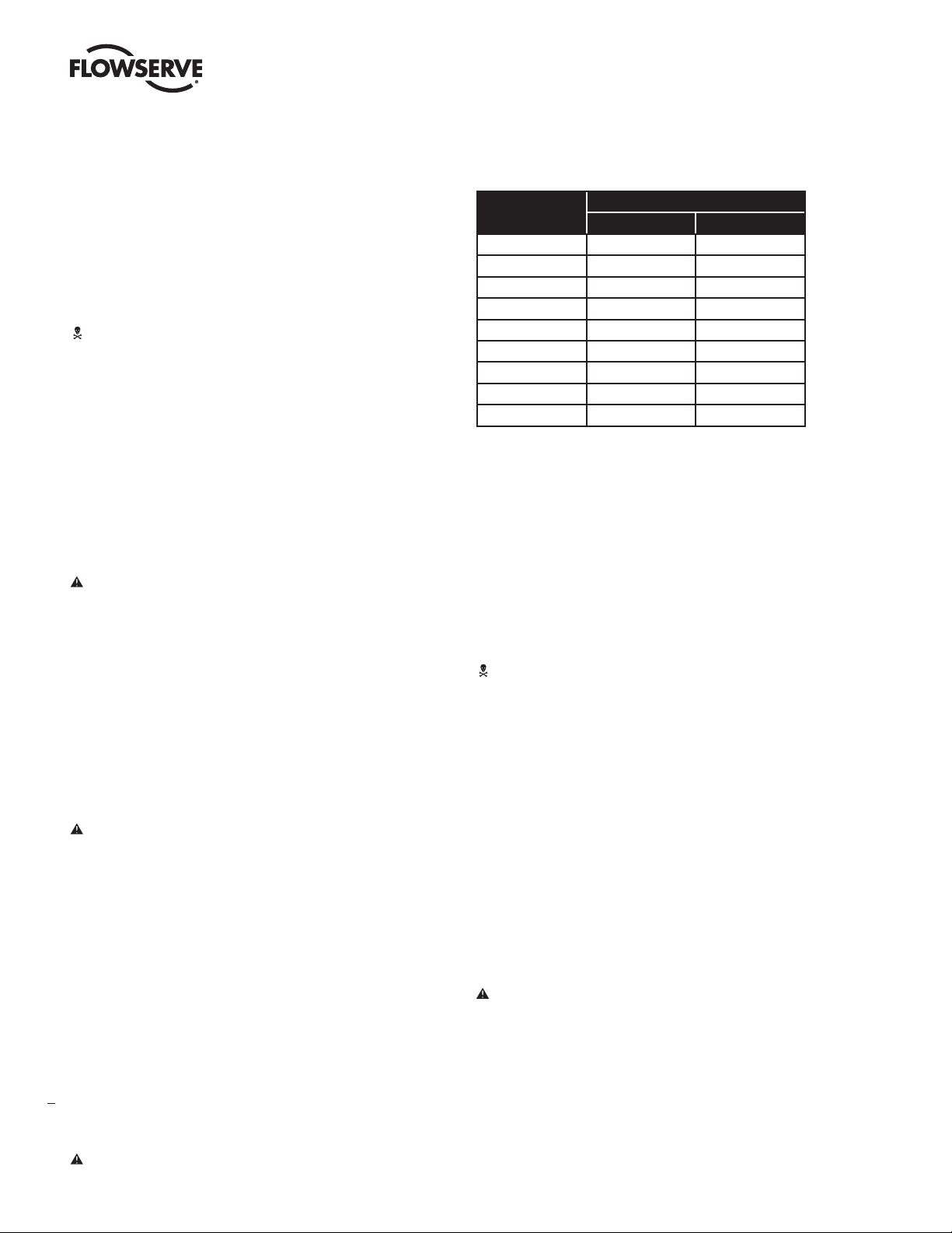
Table 1: ASME Valve Disassembly Clearance
Valve Size
(inches)
2 5 127
3 6 152
4 8 203
6 11 279
8 12 305
10 16 406
12 17 432
14 21 533
16 22 559
NOTE: In some cases, the air supply must be limited to less than 150
psi (10.3 bar). This is indicated on a sticker or type plate found near
the upper air port on the actuator cylinder. An air regulator should
be installed to ensure the supply pressure does not exceed the line
pressure indicated on the sticker.*
Clearance
inches mm
4.1 ASME Valve Quick-check
Prior to start-up, check the control valve by following these steps:
WARNING: Due to the risk of injury, it is prohibited to work
between the yoke/columns while the valve is in operation.
1. Stroke the valve and observe the plug position indicator on the stem
clamp compared to the stroke indicator plate. The plug should change
position in a smooth, linear fashion.
NOTE: Due to excessive friction, graphite packing can cause the plug
stem to move in a jerky fashion.
2. Check for full stroke by making appropriate instrument signal change.
3. Be sure to provide proper overhead clearance for the actuator to allow
for disassembly of the plug from the valve body. Refer to Table 1 for the
necessary clearance needed for valve disassembly.
4. Double-check flow direction to be sure the valve is installed correctly.
Flow direction is indicated by the arrow attached to the body.
5. If welding the valve into the line, use extreme care to avoid excess heat
buildup in the valve.
6. Connect the air supply and instrument signal lines. Throttling control
valves are equipped with a valve positioner. Refer to the appropriate
4
positioner bulletin for connections, maximum air supplies, and
maintenance instructions.*
CAUTION: On valves equipped with air filters, the air filter must
point down to perform properly. *
3. Check all air connections for leaks.*
4. Check packing box bolting for the correct adjustment. Refer to the
packing installation manual for specific details on maintaining the style
of packing supplied.
CAUTION: Do not overtighten packing. This can cause excessive packing wear and high stem friction that may impede
plug movement.
5. Make sure the valve fails in the correct direction in case of air failure.
This is done by turning off the air supply and observing the failure
direction.**
6. After a temperature excursion has occurred, bonnet flange bolting
should be retorqued to ensure bonnet gaskets do not leak. See Table 2.
Page 5
Mark 200 Control Valve FCD VLENIM0200– 12/12
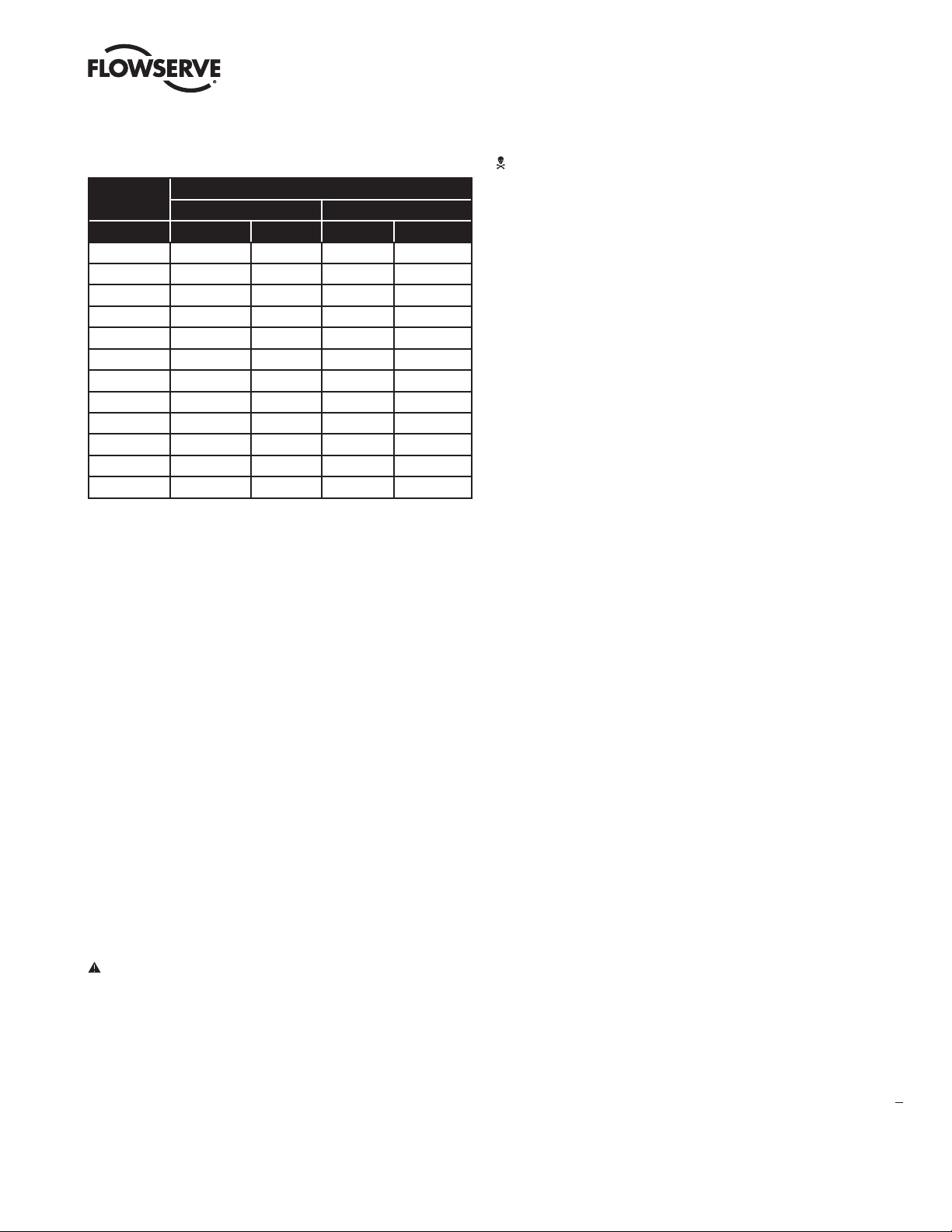
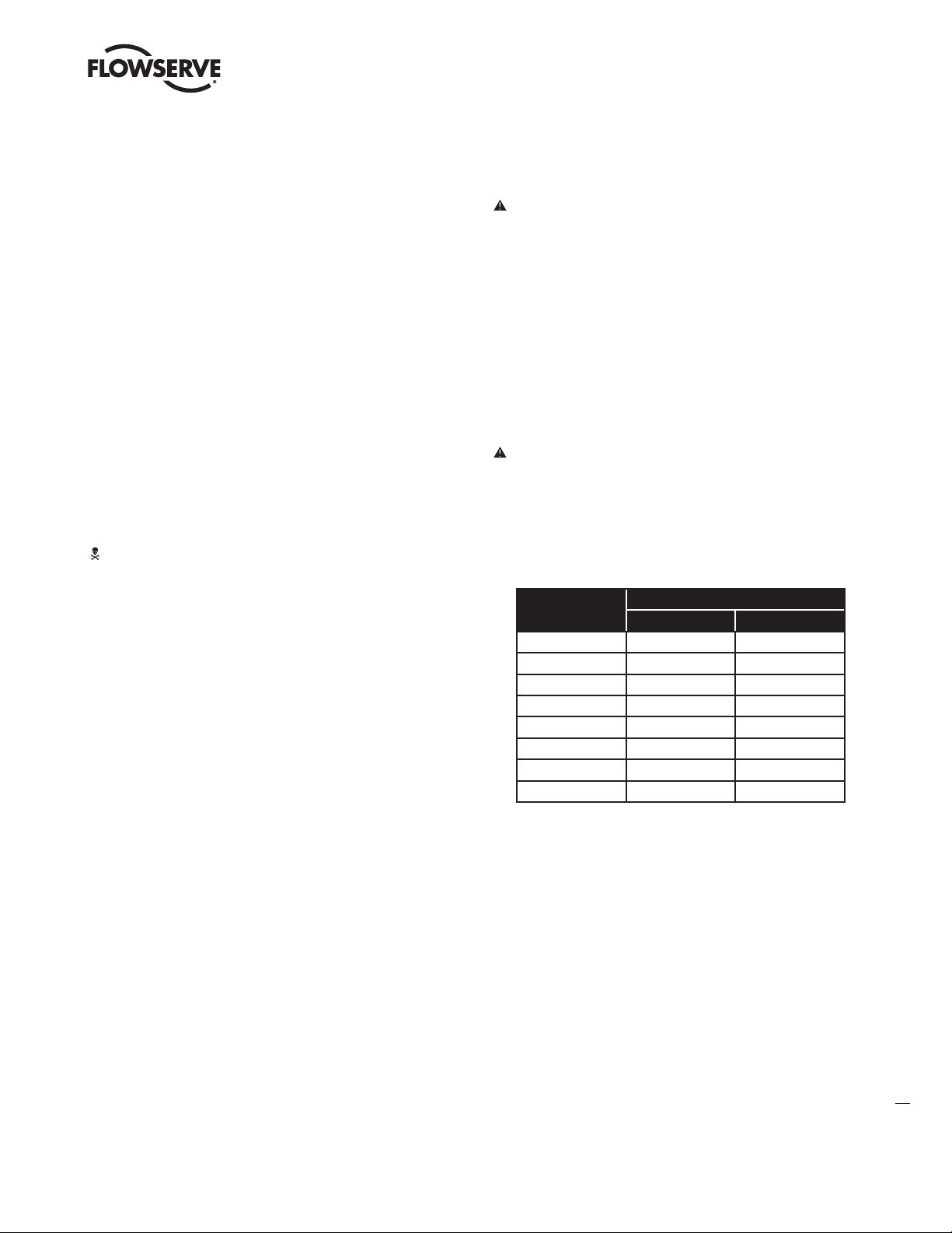
Table 2: Recommended ASME Body Bolt Torque Values
Bolt/Stud Material
Bolt Size
(inches) ft lb N m ft lb N m
1-1⁄8 520 691 380 447
1-¼ 730 990 460 624
1-3⁄8 1000 1356 630 854
1-½ 1320 1790 840 1139
1-5⁄8 1710 2318 1080 1464
1-¾ 2170 2942 1400 1898
1-7⁄8 2700 3660 1700 2305
2 3350 4542 2100 2847
2-¼ 4050 5491 2530 3430
2-½ 4850 6575 3010 4081
2-¾ 5900 8000 4400 5960
3 7273 9860 5913 8015
Carbon Steel Stainless Steel
5 ASME Valve Maintenance
At least once every six months, check for proper operation by following
the preventative maintenance steps outlined below. These steps can be
performed while the valve is in-line and, in some cases, without interrupting
service. If an internal problem is suspected, refer to the “Valve Disassembly
and Reassembly” section.
WARNING: Keep hands, hair and clothing away from all moving
parts when operating the valve. Failure to do so can cause
serious injury.
8. Make sure positioner linkage and stem clamp or coupling pieces are
securely fastened. If the stem clamp or coupling pieces are loose, check
plug thread engagement (refer to the “Reassembling the Body” section
for the correct procedure on aligning the plug with the seat.) Tighten
stem clamp nut or counter nut.
9. Ensure all accessories, brackets and bolting are securely fastened.
10. If possible, remove air supply and observe actuator for correct fail-safe
action.*
11. Check rubber actuator bellows for splits, cuts or wear.*
12. Check tightness of the actuator. Spray a soap solution around the
cylinder actuator retaining ring, adjusting screw and actuator stem
guide to check for air leaks through the O-rings. *
13. Clean any dirt and other foreign material from the plug stem.
14. If an air filter is supplied, check and replace cartridge if necessary.*
* Pneumatic operated control valves
** Pneumatic operated control valves with safety function
1. Look for signs of gasket leakage through the end flanges and bonnet.
Retorque flange and bonnet bolting (if required). See Table 2.
2. Check for fluid leakage to the atmosphere through the body drain plug, if
applicable.
3. Examine the valve for damage caused by corrosive fumes or process
drippings.
4. Clean valve and repaint areas of severe oxidation.
5. Check packing box bolting for proper tightness. Refer to the packing
installation manual for specific details on maintaining the style of
packing supplied.
CAUTION: Do not overtighten packing. This can cause excessive packing wear and high stem friction that may impede
stem movement.
6. If the valve is supplied with a lubricator fitting, check lubricant supply
and add lubricant if necessary. See product documentation or contact
the Flowserve representative.
7. If possible, stroke the valve and check for smooth, full-stroke operation.
Unsteady stem movement could indicate an internal valve problem.
5
NOTE: Due to excessive friction, graphite packing can cause the plug
stem to move in a jerky fashion.
flowserve.com
Page 6
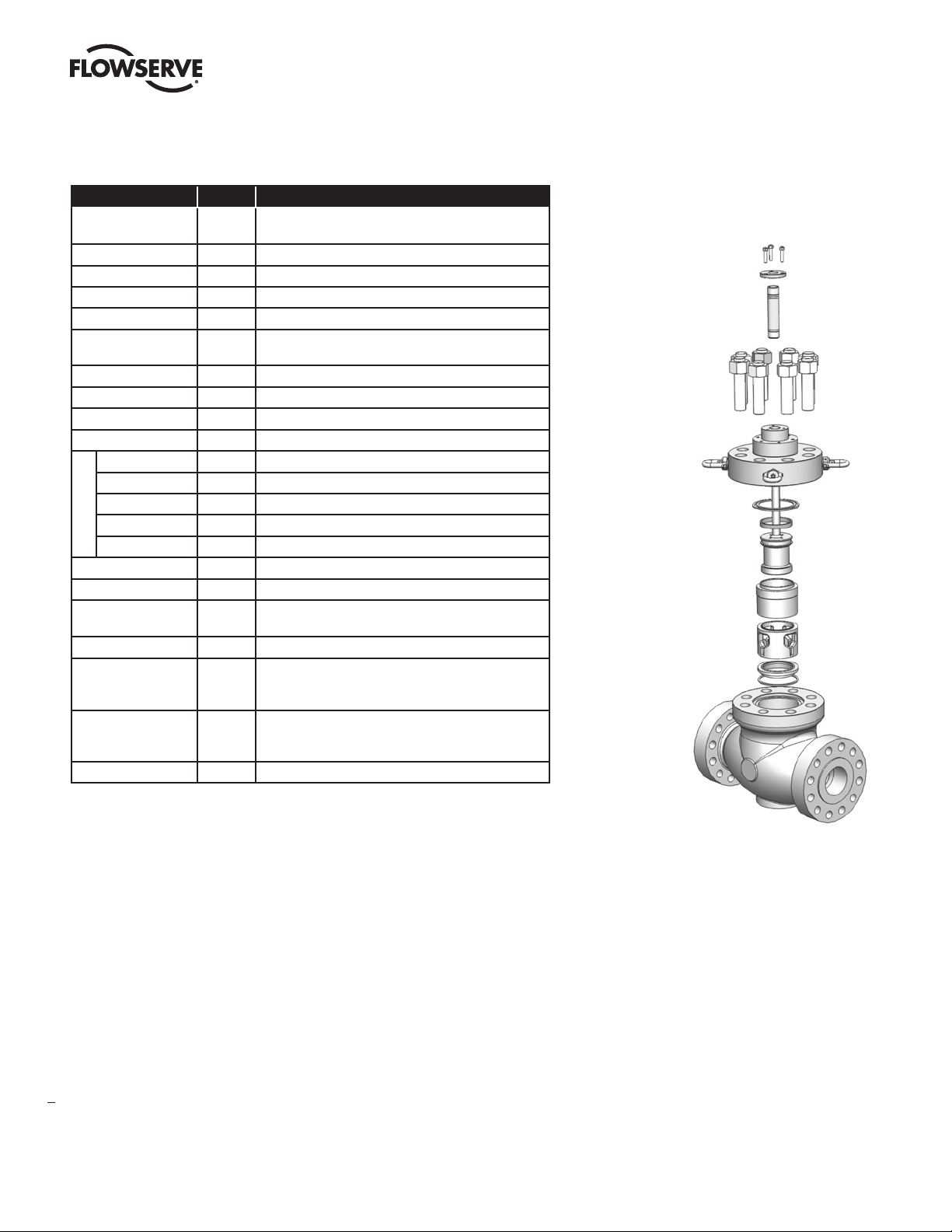
Figure 3 – Exploded Drawing of an ASME Mark 200, pressure balanced with cage
Part Item Available Materials
Body 1
Seat Ring* 20 316 SS, 316 SS / Alloy 6, 410 SS HT, 416 SS HT, 420 SS HT
Plug* 50 316 SS, 316 SS / Alloy 6, 416 SS HT, 420 SS HT, CrMo/Alloy 21
Plug Stem 51 316 SS, 316 SS / Alloy 6, 416 SS HT, 17-4PH SS
Cage 30 316 SS , 416 SS HT, CrMo/Nitrided
Pressure
Balanced Sleeve
Bonnet 40 Carbon Steel, 316 SS, CrMo, Duplex SS
Seat Gasket 55 PTFE, Spiral Graphite
Sleeve Gasket 56 PTFE, Spiral Graphite
Bonnet Gasket 58 PTFE, Spiral Graphite
O-Ring Seal 65 Buna, Viton®, EPDM, Perflouroelastomer
Back-up Ring 66 Carbon-Filled PTFE, PEEK, Vespel
PTFE Seal 65 PTFE, Glass-Loaded PTFE
Seal Types
Metal Multi-Seal 65 Rene 41
Carbon Seal 65 Carbon (Single & Triple)
Gland Flange 80 Carbon Steel
Gland Flange Bolting 109, 117 Carbon Steel
Lower Guide 83
Upper Guide 87 316 SS / GL PTFE
Packing 88
Body Bolting 108
Packing Spacers 93-99 316 SS
Carbon Steel (WCC) , 316 SS (CF8M), CrMo (WC9, C12A),
Duplex SS
316 SS, 410 SS, 410 SS HT, 420 SS HT**, 316 SS / Alloy 6,
31
CrMo/Nitrided
®
, Ryton
®
, Inconel® X-750
1
, Stainless Steel2
1
, Stainless Steel2
316 SS / GL PTFE
1, 2
, 316 SS / Graphite, Bronze C93200,
Alloy 6, Ultimet
1, 2
, 316 SS / Graphite, Bronze C93200
PTFE V-Ring
1, 2
, PTFE / Glass V-Ring, Quick-Set 9001, Braided
PTFE, AFPI, Graphite Rib/Braid, Safeguard, Sureguard, 1303
FEP, Chesterton 5800E, Sureguard XT, TA-Luft Double Graphite
B7-2H Zinc-coated 1, B7-2H Oxide-coated, B7M-2HM (NACE),
B8-8 (304 SS) 2, B8M-8M (NACE), L7-7, L7M-7M (NACE),
B16-7L, L7M-7M Uncoated (NACE)
1,2
®
Mark 200 Control Valve FCD VLENIM0200– 12/12
Gland Flange Bolting 109, 117
Gland Flange 80
Packing, Guides & Spacers
83-88, 93-99
Body Bolting 108
Bonnet 40
Bonnet & Sleeve Gasket
56 & 58
Pressure Balance Seals 65,66
Plug 50
Pressure Balanced Sleeve 31
Seat Ring 20
Seat Gasket 56
Body 1
* The seat ring and plug have hard facing of alloy 6 or other materials on the seating and guiding surfaces
** Internal Sleeve Only
1
Standard for Carbon Steel Body Construction
2
Standard for Stainless Steel Body Construction
6
Page 7

Mark 200 Control Valve FCD VLENIM0200– 12/12
ASME Disassembly and Reassembly
6.1 Disassembling the Body
To disassemble the valve body, refer to Figure 3 or 4 then proceed
as follows:
WARNING: Depressurize line to atmospheric pressure and
drain all fl uids before working on the valve. Failure to do so
can cause serious injury.
1. Fully retract the plug until the stem clamp indicator points to the open
position.
2. Remove the bonnet fl ange bolting and lift the actuator, bonnet and plug
out of the valve body.
WARNING: Danger exists in removing the actuator, bonnet and
plug, especially if PTFE plug seals are used. The sleeve may
stick to the plug and fall during disassembly, causing possible
serious injury and damage to the valve or nearby equipment.
If sleeve is observed sticking to the plug, steps 3–5 should be
consulted.
Figure 4 – ASME Mark 200 Cutaway Drawing
CAUTION: If a rubber bellows is attached to the gland fl ange,
the gland fl ange must be removed prior to removing the
actuator.
CAUTION: Heavy actuators may require a hoist. Lift the actuator
with the yoke legs using a lifting strap and a hoist. Great care
should be taken to lift the actuator and plug straight out of the
body to avoid damage to the plug and seat.
3. If the sleeve is observed sticking to the plug during removal, fully extend
the plug by applying air above the piston, allowing the sleeve to remain
in the body and the bonnet to rise above the body.
4. In the gap between the top of the sleeve and the bottom of the bonnet,
place wooden blocking of equal thickness in at least three places. The
wooden blocks must not extend in far enough that they interfere with
plug movement. The plug must be allowed to stroke up to the bonnet.
5. By applying air below the piston, retract the plug until the plug head is
freed from the sleeve. Once the plug is free from the sleeve, remove the
plug and bonnet assembly from the body.
6. Lift the sleeve out of the valve body using lifting points on the top of the
sleeve.
7. Remove cage, seat ring and gaskets from the valve body.
8. Remove the plug seals from the plug head.
9. Check to see the seating surfaces on both the seat ring and plug are
free of damage to ensure tight shutoff. Make sure the gasket surfaces
on the seat ring, bonnet and body are clean and undamaged. Inspect the
pressure balanced sleeve for scratches or other damage.
11. Turn the actuator off the plug and bonnet without allowing the plug to
rotate within the bonnet. Pull the plug carefully through the packing box.
Inspect the plug stem for damage or scoring.
NOTE: With air-to-close, fail-open valves, it may be necessary to apply
a small amount of air to the top of the actuator to move the plug away
from the bonnet. Otherwise, plug galling may occur.
CAUTION: To avoid scoring guides and plug stem, follow the
above procedure exactly.
12. If the seat surfaces need remachining, both surfaces on plug and seat
ring must be reworked. The seat angle on the plug is 36 degrees and
the seat ring is 33 degrees. Lapping is not necessary if proper assembly
procedures are followed.
CAUTION: If remachining, protect the stem while turning.
Ensure concentricity of the seat surface with the plug stem (or
outside diameter of the seat ring, if machining the seat).
13. To replace packing or change the packing box confi guration, push out
packing, spacer and guides with a dowel slightly larger than the plug
stem from underneath the bonnet.
7
10. Loosen the stem clamp and gland fl ange. Remove the yoke bolts.
fl owserve.com
Page 8

Mark 200 Control Valve FCD VLENIM0200– 12/12
6.2 Reassembling the Body
To reassemble the valve body, refer to Figure 3 or 4 then proceed as follows:
1. Install new bonnet and seat gaskets with the beveled edge up on
fluoropolymer gaskets.
NOTE: All gaskets should be replaced whenever the valve is
disassembled.
2. Relocate the seat ring. Carefully install the cage and then the sleeve
with the indexing feature provided, taking care to ensure they install
with the correct ends up.
3. Replace the plug seals on the plug, referring to Figure 5 and 6, and
observing the following directions:
WARNING: Gloves should be worn to help prevent the hands
from being pinched or burned.
PTFE Seals Heat one seal to 300°F (150°C) and slip it over the plug into the
seal groove. Thermal expansion causes the ring to stretch, thereby making it
relatively easy to slide over the plug head.
Care must be taken to prevent the seal from rolling, rather than sliding over
the plug. The second seal can be installed following the same procedures as
the first. If for any reason the second seal cannot be slipped onto the plug,
cut the seal at approximately a 30° angle (see Figure 6) and place over the
plug. Make certain the cut seal is on the low-pressure side.
Figure 5 – Seal Designs
O-ring Seals
Carbon Single Seal Carbon Triple Seal
Figure 6 – PTFE Seal Cutting Detail
PTFE Seals Metal Multi-Seal
Carbon Seals
Single Seals Each seal must be scored on a face with a sharp knife at
two places, 180 degrees apart. Holding the ring gently in a padded vise,
pull gently on the ring, breaking the ring on the score marks into two equal
pieces. Install the two pieces into the plug seal grooves with the score marks
on the pressure side.
Triple Seals Gently insert one end of seal and wrap the seal into groove.
Install the inside ring first, followed by the two outside rings with joints offset
120 degrees on all three rings (see Figure 5).
CAUTION: Install rings starting with one end and working the
ring carefully into place. Do not spread ring more than necessary. Spreading the ring too much can cause the ring to break.
8
Metal Multi-Seals Install wave spring followed by four seal rings. Stagger
ring openings by at least 90 degrees. Take care not to bend the seal rings as
they are installed.
O-ring with Back-up Rings The O-ring can stretch over plug and into
place. Spread scarf cut back-up rings until they fit on each side of O-ring as
shown in Figure 5.
Page 9

Mark 200 Control Valve FCD VLENIM0200– 12/12
4. Lower the plug into the body and sleeve. Care should be taken with the
plug seals to avoid scoring or galling the sealing surface while fitting
them into the sleeve bore. With metal multi-seals and carbon triple
seals, use a ring compressor on the rings. A suitably sized screw-type
hose clamp will also serve to compress the rings for reassembly.
5. Install sleeve gasket by centering on sleeve.
6. Lower the bonnet onto the plug and body, taking great care to avoid
scoring the plug stem.
7. Once the bonnet is resting squarely in the valve body, finger-tighten the
bonnet flange bolting.
8. Reinstall the packing and guides referring to the appropriate packing
installation manual and reinstalling new packing exactly as shown.
Make sure at least 1⁄8” (3 mm) is left at the top of packing box for the
top guide to enter. Different spacer lengths permit a wide variety of
packing configurations, such as twin seal and vacuum-pressure packing
WARNING: Valves with extended bonnets must not have
lower packing installed. Instead, lower packing rings should
be installed with the upper set. Lower packing installed in
extended bonnets will diminish the integrity of the packing
assembly.
NOTE: Graphite guide liners should be replaced each time the valve
packing is replaced. Do not rebuild the valve without new graphite liners
in the guides.
13. Slowly stroke the plug up and down to check the alignment of the plug
with the sleeve.
CAUTION: If binding or sticking is observed, discontinue
stroking the valve and reassemble using the above steps.
Failure to do so could cause serious valve damage. Contact
your Flowserve representative if binding cannot be resolved.
14. Perform a Quick Check as described in section 4.1.
Figure 7 – Bolt Patterns
Bolts Cross Bolt Tightening Pattern
4 bolts
90° apart
8 bolts
45° apart
9. Replace and tighten the packing gland and bolting. Refer to the packing
installation manual for specific details on maintaining the style of
packing supplied. Make sure gland flange is level after 3 nuts are
tightened.
10. Turn actuator back onto the body assembly, without turning the plug
inside the bonnet. Leave a 3⁄32” to 1⁄8” (2 mm to 3 mm) gap between
the mating surfaces of the bonnet and yoke. Tighten yoke bolting to
close this gap. Firmly tighten the yoke bolting.
11. Using the actuator, seat the plug two or three times to center the seat
ring using pressure on the top of the actuator.
12. Tighten the body bolting, following the bolting sequence outlined in
Figure 7. Use a minimum of four steps to reach the suggested bolt
torque values shown in Table 2. Never exceed more than 30% of the
suggested bolt torque value in a single step.
12 bolts
30° apart
16 bolts
22,5° apart
9
flowserve.com
Page 10

Mark 200 Control Valve FCD VLENIM0200– 12/12
6.3 ASME Valve Troubleshooting Chart
Problem Possible Cause Corrective Action
Stem motion impeded 1. Overtightened packing. 1. Refer to proper maintenance instructions and readjust.
2. Service temperature is beyond operating limits of trim design. 2. Reconfirm service conditions and contact factory.
3. Inadequate air supply. * 3. Check for leaks in air supply or instrument signal system; tighten
4. Malfunctioning positioner. * 4. Refer to positioner maintenance instructions.
Excessive leakage 1. Improperly tightened bonnet flange bolting. 1. Refer to step 11 of “Reassembling the Body” section for
2. Worn or damaged seat ring. 2. Disassemble valve and replace or repair seat ring.
3. Worn or damaged seat or bonnet gasket. 3. Disassemble and replace gaskets.
4. Inadequate actuator thrust. 4. Check for adequate air supply to actuator; if air supply is
5. Incorrectly adjusted plug. 5. Refer to step 9 of “Reassembling the Body” section for correct
6. Improper flow direction. 6. Refer to original specifications or contact factory.
7. Improper handwheel adjustment; handwheel acting as a limit-stop. * 7. Adjust handwheel until plug seats properly.
Inadequate flow 1. Improper plug adjustment, limiting stroke. 1. Refer to step 9 of “Reassembling the Body” section for
2. Malfunctioning positioner. * 2. Refer to positioner maintenance instructions.
3. Service conditions exceed trim design capacity. 3. Verify service conditions and consult factory.
Plug slams 1. Incorrect plug adjustment allowing improper cushion of air between
actuator piston and yoke.*
loose connections and replace leaky lines.
correct tightening procedure.
adequate, reconfirm service conditions and contact factory.
plug adjustment.
correct plug adjustment.
1. Refer to step 9 of “Reassembling the Body” section for
correct plug adjustment.
2. Inadequate air supply. * 2. Check air supply to actuator; repair leaks and remove any
3. Trim sized too large for flow rate. 3. Install reduced trim.
Valve does not fail in
correct position
* Pneumatic operated control valves
1. Incorrect flow direction. 1. Reconfirm direction and, if necessary, correct flow direction
restrictions in supply line.
through valve.
10
Page 11
Mark 200 Control Valve FCD VLENIM0200– 12/12
7 DIN Valve Unpacking
1. Careful loading and transport arrangements are required to avoid
the product suffering impact and jolting movements. Under no
circumstances should lifting gear be attached to the valve stem, travel
indicator or any peripheral units, if applicable. We recommend the use
of a length of rope that is looped around the valve head underneath the
yoke. Promptly touch up any damage to the corrosion protection.
2. Upon arrival on site, store the control valve on a solid base in a closed
room. Until its installation, the valve must be protected from the weather,
dirt or other potentially harmful influences. Under no circumstances
should the valve remain in storage for more than 6 months, as the
impregnation in the stuffing box packing evaporates and leaks may
develop. Do not remove the plugs protecting the flanges and the inside
of the control valve until it has arrived at its place of installation.
3. While unpacking the valve, check the packing list against materials
received. Lists describing valve and accessories are in each shipping
container.
WARNING: When lifting a valve using the rope, be aware that the
center of gravity may be above the lifting point. Therefore, support
must be given to prevent the actuator from rotating. Failure to do
so can cause serious injury to personnel, damage to the valve or
nearby equipment.
4. Contact your shipper immediately if there is shipping damage.
5. Should any problem arise, call your Flowserve representative.
6. The export packaging follows the packaging guidlines according to the
HPE stantards. The nonreturnable package is based on 90% recyclable
materials (cardboard box, wooden pallet etc.).
8 DIN Valve Installation
CAUTION: The valve must be installed and commissioned by
qualified staff. Qualified staff is defined as personnel who are
familiar with the installation, commissioning and operation of
this product and possess the relevant qualifications in their
field of activity.
1. Before installing the valve, clean the line of dirt, welding chips, scale or
other foreign material.
2. Whenever possible, the valve should be installed in an upright position.
Vertical installation permits easier valve maintenance. When vertical
installation is not possible contact your Flowserve representative.
CAUTION: Do not insulate extension bonnets that are provided
for hot or cold services.
3. Be sure to provide proper overhead clearance for the actuator to allow
for disassembly of the plug from the valve body. Refer to Table 3 for the
necessary clearance needed for valve disassembly.
Table 3: DIN Valve Disassembly Clearance
Valve Size
50 7 180
80 7 180
100 7 180
150 7 180
200 7 180
250 7 180
300 7 180
400 7 180
Clearance
inches mm
4. Double-check flow direction to be sure the valve is installed correctly.
Flow direction is indicated by the arrow attached to the body.
5. If welding the valve into the line, use extreme care to avoid excess heat
buildup in the valve.
6. Connect the electric power supply according the wiring diagram (see
removable actuator cover or manufacturer`s actuator documentation).
flowserve.com
11
Page 12

Mark 200 Control Valve FCD VLENIM0200– 12/12
8.1 DIN Valve Quick-check
Prior to start-up, check the control valve by following these steps:
WARNING: Due to the risk of injury, it is prohibited to work
between the yoke/columns while the valve is in operation.
1. Stroke the valve and observe the plug position indicator on the stem
clamp compared to the stroke indicator plate. The plug should change
position in a smooth, linear fashion.
NOTE: Due to excessive friction, graphite packing can cause the plug
stem to move in a jerky fashion.
2. Check for full stroke by making appropriate instrument signal change.
3. Check packing box bolting for the correct adjustment. Refer to the
packing installation manual for specific details on maintaining the style
of packing supplied.
CAUTION: Do not overtighten packing. This can cause
excessive packing wear and high stem friction that may
impede plug movement.
4. After a temperature excursion has occurred, bonnet flange bolting
should be retorqued to ensure bonnet gaskets do not leak. See Table 4.
Table 4: Recommended DIN Body Bolt Torque Values
Bolt Size
(mm) ft lb N m ft lb N m ft lb N m
M24 265 360 265 360 300 405
M27 385 525 385 525 410 555
M30 410 555 415 565 480 650
M33 630 860 650 885 740 1000
M39 1220 1650 1220 1650 1250 1700
M42 1400 1900 1400 1900 1550 2100
M52 3250 4400 3250 4400 3250 4400
1.0619, 1.5419 1.7357 1.7379
PN 160 / Body Material
9 DIN Valve Maintenance
At least once every six months, check for proper operation by following
the preventative maintenance steps outlined below. These steps can be
performed while the valve is in-line and, in some cases, without interrupting
service. If an internal problem is suspected, refer to the “Valve Disassembly
and Reassembly” section. If multiple checks in line without claim (record) it
is allowed to extend the maintenance interval by risk of plant operator.
1. Look for signs of gasket leakage through the end flanges and bonnet.
Retorque flange and bonnet bolting (if required). See Table 4.
2. Check for fluid leakage to the atmosphere through the body drain plug, if
applicable.
3. Examine the valve for damage caused by corrosive fumes or process
drippings.
4. Clean valve and repaint areas of severe oxidation.
5. Check packing box bolting for proper tightness. Refer to the packing
installation manual for specific details on maintaining the style of
packing supplied.
CAUTION: Do not overtighten packing. This can cause excessive packing wear and high stem friction that may impede
stem movement.
6. If the valve is supplied with a lubricator fitting, check lubricant supply
and add lubricant if necessary. See product documentation or contact
the Flowserve representative.
7. If possible, stroke the valve and check for smooth, full-stroke operation.
Unsteady stem movement could indicate an internal valve problem.
NOTE: Due to excessive friction, graphite packing can cause the plug
stem to move in a jerky fashion.
WARNING: Keep hands, hair and clothing away from all moving
parts when operating the valve. Failure to do so can cause
serious injury.
Bolt Size
(mm) ft lb N m ft lb N m
M24 265 360 280 (300)* 380 (410)*
M30 427 580 500 680
M39 1150 1570 1220 1660
M45 2060 2800 2060 2800
12
M48 2500 3400 2500 3400
M56 4050 5500 4050 5500
M72 8550 11600 8550 11600
* Nominal Size DN 80 only
PN 250 / Body Material
1.0619, 1.5419, 1.7357 1.7379
8. Make sure positioner linkage and stem clamp or coupling pieces are
securely fastened. If the stem clamp or coupling pieces are loose, check
plug thread engagement (refer to the “Reassembling the Body” section
for the correct procedure on aligning the plug with the seat.) Tighten
stem clamp nut or counter nut.
9. Ensure all accessories, brackets and bolting are securely fastened.
10. Clean any dirt and other foreign material from the plug stem.
Page 13

Mark 200 Control Valve FCD VLENIM0200– 12/12
Figure 8 – Exploded drawing of a DIN Mark 200 with screwed-in seat ring; mounting shown for electric actuator
Part Item Available Materials
Body 1.1 1.0619 1.5419 1.7357 1.7379
Bonnet Gasket 1.2 Pure Graphite on Support Plate from C-276
Stud Bolt 1.3 1.7218 (KG) 1.7709 (GA) 1.4923 (V)
Hex Nut 1.4 1.7218 (KG) 1.7709 (GA) 1.4923 (V)
Extension Sleeve 1.5 1.7218 (KG) 1.7709 (GA) 1.4923 (V)
Screwed Seat 2.1 1.4122 1.4922
Contoured Plug 2.2 1.4122 1.4922
Linear Thrust Unit 12.5
Lock Nut 12.4
Stroke Indicator Disk 5.9
Hex Nut 5.7
Hex Nut 3.6
Gland Flange 3.4
Packing Box 3.3
Bottom Ring 3.2
Bonnet 3.1
Hex Nut 1.4
Extension Sleeve 1.5
Spring Pin 2.3 A2
Stem 2.4 1.4122 1.4922
Profil Ring 2.5 Pure Graphite
Bonnet 3.1 1.0460 1.5415 1.7335 1.7383
Bottom Ring 3.2 1.4922
Packing Box 3.3 Pure Graphite Rings
Gland Flange 3.4 1.4922
Stud Bolt 3.5 1.4923 (V)
Hex Nut 3.6 1.4923 (V)
Yoke Rod 5.1 1.4122
Flange 5.2 1.0460
Hex Nut
Stroke indicator scale 5.4 Aluminium
Hex Bolt 5.5 A2 - 70
Washer 5.6 A2
Hex Nut 5.7 A2 - 50
Stroke indicator Disk 5.9 1.0038
Threaded Ring 5.10 1.0460
Set Screw 5.11 45 H
5.3 A2 - 70
Body Gasket 1.2
Trim 2.2 + 2.4
Screwed Seat 2.1
Seat Gasket 2.5
Stud Bolt 1.3
Body 1.1
13
flowserve.com
Page 14

Mark 200 Control Valve FCD VLENIM0200– 12/12
DIN Disassembly and Reassembly
10.1 Disassembling the Body
To disassemble the valve body, refer to Figure 8 or 9 then proceed
as follows:
WARNING: Depressurize line to atmospheric pressure and
drain all fluids before working on the valve. Failure to do so
can cause serious injury.
1. Fully retract the plug until the stem clamp indicator points to the
open position.
2. Remove the actuator bolting and lift the actuator out of the
linear thrust unit.
CAUTION: Heavy actuators may require a hoist.
3. Unlock the hex nut (5.7) counter clockwise.
4. Unlock the linear thrust unit - lock nut counter clockwise.
5. Unscrew the complete linear thrust unit counter clockwise.
6. Measure the distance from stroke indicator disk (5.9) to the stem
(2.4) top edge. Make a note of the dimension, you will need it for
reassembling.
7. Remove the stroke indicator disk (5.9) and unscrew the hex nut (5.7).
8. Unscrew hex nuts (5.3) and remove the extension sleeves (1.5).
9. Unscrew hex nuts (3.6).
10. Remove gland flange (3.4).
11. Turn the special tool (ring nut, see Table 10.3) on the stem and put in
place slowly.
WARNING: Danger exists in removing the bonnet and plug with
piston ring balancing. The balanced ring may stick to the plug
and fall during disassembly, causing possible serious injury
and damage to the valve or nearby equipment.
Figure 9 – DIN Mark 200 Cutaway Drawing
Table 5: DIN Mark 200 Required Torque for Screwed-in Seat Ring
PN250
Moment [Nm]
Torque [ft lb]
420
310
1290
950
1930
1420
4800
3540
8150
6000
13400
10000
19600
14400
26400
19400
DN
50
80
100
150
200
250
300
400
PN160
Moment [Nm]
Torque [ft lb]
190
140
590
435
880
650
2200
1620
3700
2730
6100
4500
8900
6550
12000
8850
12. Remove flat gasket (1.2).
13. Insert special tool (change seat tool, see Table 10.3) in the body and
remove using a suitable torque wrench (see table 5).
14. Remove screwed seat (2.1) and profile ring (2.5).
14
15. Remove plug - unit (2.2, 2.3, 2.4) from the bonnet.
16. Remove packing (3.3) and bottom ring (3.2) with special tool
(packing driver tool, see Table 10.3).
Page 15

Mark 200 Control Valve FCD VLENIM0200– 12/12
10.2 Reassembling the Body
To reassemble the valve body, refer to Figure 8 or 9 then proceed as follows:
1. Install new profile ring (2.5) and screwed seat (2.1).
NOTE: Clean and inspect all sealing surfaces, threads and remove
damaged parts. Allways use new gaskets whenever the valve is
disassembled.
2. Insert special tool (change seat tool, see Table 10.3) in the body and
turn using a suitable torque wrench (see Table 5).
3. Lower plug unit (2.2, 2.3, 2.4) in the body and put it in the
screwed seat.
NOTE: Check the stem surface for damage. A damaged stem must
be replaced.
4. Install new flat gasket (1.2).
5. Lower the bonnet (3.1) onto the plug unit and body carefully.
NOTE: Take great care to avoid scoring the stem.
6. Fit the extension sleeves (1.5) onto the stud bolts (1.3) and fingertighten
the nuts (1.4).
13. Screw on the linear thrust unit. Lock nut onto the linear thrust
unit clockwise and secure it. Do the same with the hex nut (5.7).
NOTE: The stroke indicator disk should be shown in the open position on
the stroke indicator plate.
14. Replace the multi turn actuator.
15. After replacing the valve in the pipe, perform three full strokes and
check the thigtening torque of the nuts (3.6). Retighten the nuts as
necessary.
16. Log the maintenance interval and the work performed.
Figure 10 – Bolt Patterns
Bolts Cross Bolt Tightening Pattern
8 bolts
45° apart
7. Tighten the nuts (1.4) in four steps (crosswise with 30%, 60%, 100%
and all round 100%) according to the pattern (Figure 10).
NOTE: Check the movement of the plug by lifting (10 mm) between the
steps. If it is hard to move, loosen the nuts and start again.
8. Lower the bottom ring (3.2) and the new packing (3.3).
NOTE: Instal one ring after the other. To do this, use a tamper and push
in each ring individually, carefully and complete. When inserting the
other rings, rotate them each by 180° from their overlapping points.
9. Lubricate the thread and all bearing surfaces (underside of the nuts)
with a suitable, approved lubricant.
10. Place the gland flange (3.4) back on and tighten the nuts (3.6),
alternating evenly in accordance with the instructions from the packing
manufacturer.
NOTE: Tightening unevenly can cause the packing gland follower to jam,
which can result in stem damage.
11. Screw the hex nut (5.7) onto the stem (2.2) and replace the stroke
indicator disk (5.9). Recall the distance between top edge of stem and
replace it.
12 bolts
30° apart
16 bolts
22,5° apart
20 bolts
18° apart
12. Lower the linear thrust unit. Lock nut onto the stroke indicator disk and
screw the complete linear thrust unit onto the stem clockwise.
15
flowserve.com
Page 16

10.3 Special Tools
Special Tools Use
Mark 200 Control Valve FCD VLENIM0200– 12/12
Ring Nut Tool
Recommended tool for disassembling and
reassembing
For part no. see spare parts catalog
Seat Change Tool
Recommended tool for disassembling and
reassembling the screwed in seat
For part no. see spare parts catalog
16
Packing Driver Tool
Recommended tool for disassembling
the packing
For part no. see spare parts catalog
Page 17

Mark 200 Control Valve FCD VLENIM0200– 12/12
11 DIN Valve Troubleshooting Chart
Problem Possible Cause Corrective Action
Stem motion impeded 1. Overtightened packing. 1. Refer to proper maintenance instructions and readjust.
2. Service temperature is beyond operating limits of trim design. 2. Reconfirm service conditions and contact factory.
Excessive leakage 1. Improperly tightened bonnet flange bolting. 1. Refer to step 11 of “Reassembling the Body” section for
2. Worn or damaged seat ring. 2. Disassemble valve and replace or repair seat ring.
3. Worn or damaged seat or bonnet gasket. 3. Disassemble and replace gaskets.
4. Inadequate actuator thrust. 4. Check for adequate multi turn actuator,
5. Incorrectly adjusted plug. 5. Refer to step 9 of “Reassembling the Body” section for correct
6. Improper flow direction. 6. Refer to original specifications or contact factory.
Inadequate flow 1. Improper plug adjustment, limiting stroke. 1. Refer to step 9 of “Reassembling the Body” section for
2. Service conditions exceed trim design capacity. 2. Verify service conditions and consult factory.
Plug slams 1. Trim sized too large for flow rate 1. Install reduced trim.
correct tightening procedure.
reconfirm service conditions and contact factory.
plug adjustment.
correct plug adjustment.
flowserve.com
17
Page 18

Pages available for technician’s notes.
Mark 200 Control Valve FCD VLENIM0200– 12/12
18
Page 19

Pages available for technician’s notes.
Mark 200 Control Valve FCD VLENIM0200– 12/12
flowserve.com
19
Page 20

FCD VLENIM0200-00 Printed in USA. December 2012.
To find your local Flowserve representative
or for more information about Flowserve Corporation, visit
www.flowserve.com.
USA
Flowserve Flow Control Division
1350 N. Mt. Springs Parkway
Springville, UT 84663
USA
Phone: +1 801 489 8611
Fax: +1 801 489 3719
Austria
Flowserve Control Valves Gmbh
Control Valves-Villach Operation
Kasernengasse 6
9500 Villach
Austria
Phone: 43 (0) 4242 41 181 0
Fax: 43 (0) 4242 41181 50
India
Flowserve India Controls Pvt Ltd.
Plot # 4, 1A, Road #8 EPIP
Whitefield
Bangalore, Karnataka, 560066
India
Phone: 91 80 40146200
Fax: 91 80 28410286
China
Flowserve Fluid Motion and
Control (Suzhou)Co., Ltd.
No.35, Baiyu Road,
Suzhou Industrial Park, Suzhou
Jiangsu Province, P.R. 215021
China
Phone: 86 512 6288 8790
Fax: 86 512 6288 8736
Flowserve Corporation has established industry leadership in the design and manufacture of its products. When properly selected, this Flowserve product is designed to perform its intended function
safely during its useful life. However, the purchaser or user of Flowserve products should be aware that Flowserve products might be used in numerous applications under a wide variety of industrial service conditions. Although Flowserve can (and often does) provide general guidelines, it cannot provide specific data and warnings for all possible applications. The purchaser/user must therefore assume
the ultimate responsibility for the proper sizing and selection, installation, operation, and maintenance of Flowserve products. The purchaser/user should read and understand the Installation Operation
Maintenance (IOM) instructions included with the product, and train its employees and contractors in the safe use of Flowserve products in connection with the specific application.
While the information and specifications contained in this literature are believed to be accurate, they are supplied for informative purposes only and should not be considered certified or as a guarantee of
satisfactory results by reliance thereon. Nothing contained herein is to be construed as a warranty or guarantee, express or implied, regarding any matter with respect to this product. Because Flowserve
is continually improving and upgrading its product design, the specifications, dimensions and information contained herein are subject to change without notice. Should any question arise concerning
these provisions, the purchaser/user should contact Flowserve Corporation at any one of its worldwide operations or offices.
© 2012 Flowserve Corporation, Irving, Texas, USA. Flowserve is a registered trademark of Flowserve Corporation.
flowserve.com
Saudi Arabia
Flowserve Abahsain Flow Control
Co., Ltd.
Makkah Road, Phase 4
Plot 10 & 12, 2nd Industrial City
Damman, Kingdom of Saudi Arabia
Phone: +966 3 857 3150 X 243
Fax: +966 3 8574243
 Loading...