

Page 1
USER INSTRUCTIONS
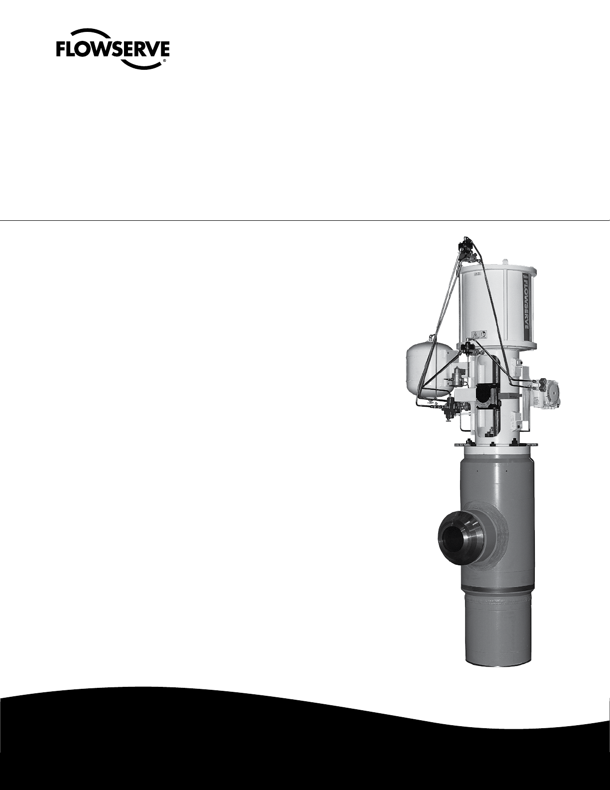
Valtek Mark 14
Control Valves
FCD VLENIM0115-00 – 06/06
Installation
Operation
Maintenance
Experience In Motion
Page 2

Valtek Mark 14 Control Valves FCD VLENIM0115-00 – 06/06
2
Page 3

Valtek Mark 14 Control Valves FCD VLENIM0115-00 – 06/06
Contents
1 General Information 4
1.1 Using
1.2 Applicability
1.3 Terms Concerning Safety
1.4 Protective Clothing
1.5 Qualified Personnel
1.6 Spare Parts
1.7 Service / Repair
1.8 Storage
2 Unpacking
3 Installation
4 Quick-check
5 Valve Maintenance
6 Disassembly and Inspection
7 Reassembly and Installation
4
4
4
4
5
5
5
5
5
6
6
7
8
9
Figures
Figure 1 – Bonnet and Seat Retaining Rings 8
Figure 2 – Pressure Seal Assembly 11
Figure 3 – Bonnet Bolting 12
Figure 4 – Exploded View 13
Figure 5 – Cross Section
14
Tables
Table 1 – Severe Service Trim Bolt Torque Values 10
Table 2 – Seat and Bonnet Torque Values 1
Table 3 – Plug Adjustment 1
1
3
3
flowserve.com
Page 4

Valtek Mark 14 Control Valves FCD VLENIM0115-00 – 06/06
1 General Information
1.1 Using
The following instructions are designed to assist in unpacking, installing and performing
maintenance as required on Flowserve products. Product users and maintenance personnel
should thoroughly review this bulletin prior to unpacking, installing, operating, or performing
any maintenance. In most cases, Flowserve valves, actuators and accessories are designed for
specific applications (e.g. with regard to medium, pressure, and temperature). For this reason,
they should not be used in other applications without first contacting the manufacturer. The
product Installation, Operation, and Maintenance Instructions provides important additional
safety information.
1.2 Applicability
The following instructions are applicable to the maintenance and installation of Flowserve
Valtek Mark 14 control valves. These instructions cannot claim to cover all details of all
possible product variations, nor can they provide information for every possible example of
installation, operation or maintenance. This means that the instructions normally include only
the directions to be followed by qualified personal using the product for is defined purpose. If
there are any uncertainties in this respect, particularly in the event of missing product-related
information, clarification must be obtained via the appropriate Flowserve sales office. All
Flowserve User Manuals are available at www.flowserve.com.
1.3 Terms Concerning Safety
1.3.1 The safety terms DANGER, WARNING, CAUTION and NOTE are used in these instructions to
highlight particular dangers and/or to provide additional information on aspects that may not
be readily apparent.
DANGER: Indicates that death, severe personal injury and/or substantial property damage will
b
occur if proper precautions are not taken.
WARNING: Indicates that death, severe personal injury and/or substantial property damage can
c
occur if proper precautions are not taken.
CAUTION: Indicates that minor personal injury and/or property damage can occur if proper
a
precautions are not taken.
NOTE: Indicates and provides additional technical information, which may not be obvious, even to
qualified personnel.
1.3.2 Compliance with other notes, which may not be particularly emphasized, with regard to trans
port, assembly, operation and maintenance and with regard to technical documentation (e.g.
in the operating instructions, product documentation, or on the product itself) is essential, in
order to avoid faults, which can directly or indirectly cause severe personal injury or property
damage.
-
4
Page 5

Valtek Mark 14 Control Valves FCD VLENIM0115-00 – 06/06
1.4 Protective Clothing
Flowserve products are often used in problematic applications (e.g. under extremely high
pressures with dangerous, toxic or corrosive mediums). When performing service, inspection
or repair operations always ensure that the valve and actuator are depressurized and that the
valve has been cleaned and is free from harmful substances. In such cases, pay particular
attention to personal protection (e.g. protective clothing, gloves, glasses etc.).
1.5 Qualified Personnel
Qualified personnel are people who, on account of their training, experience and instruction
and their knowledge of relevant standards, specifications, accident prevention regulations and
operating conditions, have been authorized by those responsible for the safety of the plant to
perform the necessary work and who can recognize and avoid possible dangers.
1.6 Spare Parts
Use only Flowserve original spare parts. Flowserve cannot accept responsibility for any
damages that occur from using spare parts or fastening materials from other manufactures. If
Flowserve products (especially sealing materials) have been on store for long periods of time
check them for corrosion or deterioration before putting them into use.
1.7 Service / Repair
To avoid possible injury to personnel or damage to products, safety terms must be strictly
adhered to. Modifying this product, substituting non-factory parts, or using maintenance
procedures other than those outlined in these Installation, Operation, and Maintenance
Instructions could drastically affect performance, be hazardous to personnel and equipment,
and may void existing warranties. Between the actuator and the valve there are moving parts.
To avoid injury, Flowserve provides pinch-point-protection in the form of cover plates, especially where side-mounted positioners are fitted. If these plates are removed for inspection,
service or repair special attention is required. After completing work the cover plates must be
refitted. Apart from the operating instructions and the obligatory accident prevention directives valid in the country of use, all recognized regulations for safety and good engineering
practices must be followed.
WARNING: Before products are returned to Flowserve for repair or service, Flowserve must be
c
provided with a certificate that confirms that the product has been decontaminated and is clean.
Flowserve will not accept deliveries if a certificate has not been provided (a form can be obtained
from Flowserve).
1.8 Storage
In most cases, Flowserve products are manufactured from stainless steel. Products not
manufactured from stainless steel are provided with an epoxy resin coating. This means that
Flowserve products are well protected from corrosion. Nevertheless, Flowserve products must
be stored adequately in a clean, dry environment. Plastic caps are fitted to protect the flange
faces and prevent the ingress of foreign materials. These caps should not be removed until the
valve is actually mounted into the system.
5
flowserve.com
Page 6

Valtek Mark 14 Control Valves FCD VLENIM0115-00 – 06/06
2 Unpacking
2.1 While unpacking the valve, check the packing list against the materials received. Lists
describing the valve and accessories are included in each shipping container.
2.2 When lifting the valve from shipping container, use straps through the yoke legs, or the lifting
lugs attached to the yoke bolting. Take care to position lifting straps to avoid damage to the
tubing and mounted accessories.
WARNING: When lifting a valve be aware that the center of gravity may be above the lifting point.
c
Therefore, support must be given to prevent the valve from rotating. Failure to do so can cause
serious injury to personnel and damage to the valve and nearby equipment.
2.3 Contact your shipper immediately if there is shipping damage.
2.4 Should any problem arise, call your Flowserve representative.
3 Installation
DANGER: Before installation check the order number, serial number, and/or the tag number to
b
ensure that the valve and actuator being installed are correct for the intended application.
CAUTION: Do not insulate extensions that are provided for hot or cold services.
a
CAUTION: On valves equipped with air filters, the air filter must point down to perform properly.
a
NOTE: In some rare cases, the air supply must be limited to less than 150 psi (10.3 bar). This is
indicated on a sticker found near the upper air port on the actuator cylinder. An air regulator should
be installed to ensure the supply pressure does not exceed the line pressure indicated on the sticker.
3.1 Pipelines must be correctly aligned to ensure that the valve is not fitted under tension.
3.2 Fire protection must be provided by the user.
3.3 Before installing the valve, clean the line of dirt, welding chips, scale and other foreign
material.
3.4 Whenever possible, the valve should be installed in an upright position. Vertical installation
permits easier valve maintenance.
3.5 Be sure to provide proper overhead clearance for the actuator to allow for disassembly of
the plug from the valve body. Refer to the appropriate actuator User Instructions for proper
clearances. Actuator User Instructions are available at www.flowserve.com.
3.6 Double-check flow direction to be sure the valve is installed correctly. Flow direction is
indicated by the arrow attached to the body.
3.7 If welding the valve into the line, use extreme care to avoid excess heat buildup in the valve.
3.8 Connect the air supply and instrument signal lines. Throttling control valves are equipped with
a valve positioner. Refer to the appropriate positioner bulletin for connections, maximum air
supplies, and maintenance instructions.
6
Page 7

Valtek Mark 14 Control Valves FCD VLENIM0115-00 – 06/06
4 Quick-check
Prior to start-up, check the control valve by following these steps:
4.1 Stroke the valve and observe the plug position indicator on the stem clamp compared to the
stroke indicator plate. The plug should change position in a smooth, linear fashion.
NOTE: Due to excessive friction, graphite packing can cause the plug stem to move in a jerky fashion.
4.2 Check for full stroke by making appropriate instrument signal changes.
4.3 Check all air connections for leaks.
4.4 Check packing box bolting for the correct adjustment. Refer to the packing installation manual
for specific details on maintaining the style of packing supplied.
CAUTION: Do not overtighten packing. This can cause excessive packing wear and high stem
a
friction that may impede plug movement.
4.5 Make sure the valve fails in the correct direction in case of air failure. This is done by turning
off the air supply and observing the failure direction.
4.6 After a temperature excursion has occurred, bonnet flange bolting should be re-torqued to
ensure bonnet seals do not leak.
5 Valve Maintenance
At least once every six months, check for proper operation by following the preventative maintenance steps outlined below. These steps can be performed while the valve is in-line and, in some
cases, without interrupting service. If an internal problem is suspected, refer to Section 6, Valve
Disassembly and Inspection.
5.1 Look for signs of gasket leakage through the end flanges and bonnet. Re-torque flange and
bonnet bolting (if required).
5.2 Examine the valve for damage caused by corrosive fumes or process drippings.
5.3 Clean valve and repaint areas of severe oxidation.
5.4 Check packing box bolting for proper tightness. Refer to the packing installation manual for
specific details on maintaining the style of packing supplied.
CAUTION: Do not overtighten packing. This can cause excessive packing wear and high stem
a
friction that may impede stem movement.
5.5 If possible, stroke the valve and check for smooth, full-stroke operation. Unsteady stem move
ment could indicate an internal valve problem.
-
NOTE: Due to excessive friction, graphite packing can cause the plug stem to move in a jerky fashion.
WARNING: Keep hands, hair and clothing away from all moving parts when operating the valve.
c
Failure to do so can cause serious injury.
5.6 Make sure positioner linkage and stem clamp are securely fastened. If the stem clamp is
loose, check plug thread engagement (refer to the “Reassembly and Installation” section for
the correct procedure on aligning the plug with the seat). Tighten stem clamp nut.
7
flowserve.com
Page 8

Valtek Mark 14 Control Valves FCD VLENIM0115-00 – 06/06
Remove First
Install Last
Remove First
Install Last
5.7 Ensure all accessories, brackets and bolting are securely fastened.
5.8 If possible, remove air supply and observe actuator for correct fail-safe action.
5.9 Check rubber actuator bellows for splits, cuts or wear.
5.10 Spray a soap solution around the actuator cylinder retaining ring and actuator stem guide to
check for air leaks through the O-rings.
5.11 Clean any dirt and other foreign material from the plug stem.
5.12 If an air filter is supplied, check and replace cartridge if necessary.
6 Disassembly and Inspection
To disassemble Mark 14 control valves refer to Figure 4 and 5 and proceed as follows:
WARNING: Depressurize line to atmospheric pressure and drain all fluids before working on the
c
valve. Failure to do so can cause serious injury.
6.1 Remove the air supply from the actuator. Remove the split stem clamp and yoke bolts. Then
remove the actuator from the body sub-assembly by lifting the actuator straight up.
CAUTION: Heavy actuators will require a hoist. Lift the actuator with the yoke legs using a lifting
a
strap and a hoist. Care should be taken to lift the actuator straight off the body to avoid damage.
WARNING: When lifting actuators, be aware that the center of gravity may be above the lifting
c
point. Support must be given to prevent the actuator from rotating. Failure to do so can cause
serious injury to personnel and damage to the actuator and nearby equipment.
6.2 Remove the gland flange bolting and the gland flange from the bonnet.
6.3 Loosen the bonnet flange socket head bolting and remove the bolts and the disk springs
underneath them.
6.4 Remove the bonnet flange.
6.5 If the bonnet has not dropped down to the body/bonnet shelf, push or tap the bonnet with a
rubber mallet until it drops down enough to allow removal of the segmented bonnet retaining
ring.
6.6 Remove the four pieces of the bonnet retaining ring, smaller pieces first. If needed, place a
¼" rod or punch tool through the holes in the body and knock the retaining ring segments in
towards the bonnet. Refer to Figure 1 to determine the order of removal.
Figure 1 – Bonnet and Seat Retaining Rings
8
Page 9

Valtek Mark 14 Control Valves FCD VLENIM0115-00 – 06/06
6.7 Place lifting rings in both gland flange bolt holes in the bonnet and slowly pull the bonnet,
retaining ring segments, bonnet seal spacer and the bonnet pressure-seal out of the body.
WARNING:
c
could damage the plug and cause damage to the other equipment as well as injury to personnel.
If the plug begins to lift as the bonnet is removed, tap the top of the plug stem with a rubber
mallet to keep the plug in place. Do not remove the plug with the bonnet.
NOTE: The pressure seal may expand as it passes by the retaining ring groove and prevent the
bonnet from coming out. In this event, lower the bonnet back down into the body and remove the
pressure seal independently.
6.8 To replace packing or change the packing box configuration, push out packing, spacer and
6.9 Remove the pilot plug assembly from the valve by lifting on the plug stem threads. For
6.10 With a long extension on a socket head ratchet, remove the seat retaining ring bolts. Remove
6.11 Place two threaded lifting rings in the seat ring lifting holes. Carefully lift the seat ring
NOTE: The pressure seal may expand as it passes by the retaining ring groove and prevent the seat
ring from coming out. In this event lower the seat ring back down into the body and remove the
pressure seal independently.
It is possible for the plug to lift out with the bonnet. If the plug were then to fall free, it
guides with a dowel slightly larger than the plug stem from underneath the bonnet.
instructions on working with pilot operated plug assemblies please refer to Pilot Operated
Trim IOM (Document number VLENIM0064). To obtain a PDF of this IOM, visit
www.flowserve.com
the four seat retaining ring segments. Two of the retaining rings are locked into position by the
other two rings. See Figure 1 to determine which rings must be removed first.
assembly, disk spring retainer, disk spring, seat seal retainer and the seat seal out of the body.
6.12 If the seat ring seating surfaces need re-machining, both surfaces on the plug and seat ring
must be reworked. The seat angle on the plug is 36 degrees and the seat ring is 33 degrees
with respect to the centerline. Lapping is not necessary
6.13 If the seat surface is to be refinished the seat may be left attached to the severe service trim as
long as steps are taken to cover the openings of the trim to prevent metal chip ingress.
6.14 If removal of the severe service stack is required, grind the tack welds off of the socket head
bolts and remove each bolt from the seat ring.
6.15 The lower MegaStream plate is not intended to be removed. If it needs to be removed, the
retaining ring would have to be carefully machined out of the body and the threads in the body
would have to be re-tapped.
NOTE: Carefully inspect the primary plug lower skirt guiding surface and severe service trim bore
for signs of galling and scoring. Superficial scoring can be removed with a light application of emery
cloth. If more serious scoring exists, contact your local Valtek control valve representative.
NOTE: Damaged pilot springs should be replaced.
9
flowserve.com
Page 10

Valtek Mark 14 Control Valves FCD VLENIM0115-00 – 06/06
7 Reassembly and Installation
7.1 Before re-assembly, carefully inspect the body pressure seal sealing surfaces. These are the
cylindrical surfaces just beneath the and seat retaining ring grooves. If these surfaces are
damaged, they must be reworked to provide a 32 Ra surface finish. Also ensure that the body
shelf that supports the seat ring is free from damage and is clean.
7.2 If the MegaStream plate has been removed from the body, place the plate in the end of the
body with the boss facing the body gallery. Thread in the plate retainer tightly against the plate
and heavily peen the threads to prevent the retainer from unscrewing during service.
7.3 If the seat assembly has been disassembled, index the severe service trim into the seat ring.
7.3.1 Liberally apply thread locking compound (Loctite Blue or equivalent) on the threads of
the seat assembly bolts and thread them into the seat ring. Using Table 1, tighten the
bolts to the values according to the bolt material.
Table 1 – Severe Service Trim Bolt Torque Values
Bolt Size
inches ft-lb N m ft-lb N m ft-lb N m
3
⁄8 24 32.5 19 25.8 15 20.3
7
⁄16 39 52.9 31 42.0 23 31.2
1
⁄2 60 81.3 48 65.1 36 48.8
9
⁄16 87 118 70 94.9 52 70.5
5
⁄8 121 164 97 132 72 97.6
3
⁄4 216 293 173 235 129 175
All values are +/- 10%
Inconel A193 B7/B16 A193 B8
Bolt Material
10
7.3.2 Check the alignment of the seat ring and stack by inserting the plug into the seat
assembly and moving it back and forth, checking for sticking or binding.
7.3.3 Tack-weld each socket head bolt with a compatible weld material. Weld near the OD of
the severe service trim to facilitate the ease of removing the weld later.
7.4 Lower the entire seat assembly into the body with threaded lifting rings in the seat ring.
NOTE: It is critical that the severe service stack centers and indexes over and around the boss located
on the MegaStream plate.
7.5 Carefully install the pressure seal into the body and around the seat ring. Mark 14 pressure
seals have three metal anti-extrusion rings on the seal corners. The side of the seal with two
metal rings must face up when installed. See Figure 2 to determine the correct installation
position.
Page 11

Valtek Mark 14 Control Valves FCD VLENIM0115-00 – 06/06
Centerline
Disc
Spring
Retainer
Disc
Spring
Pressure
Seal
Retainer
Pressure
Seal
Centerline
Disc
Spring
Retainer
Disc
Spring
Pressure
Seal
Retainer
Pressure
Seal
Figure 2 – Pressure Seal Assembly
7.6 Refer to Figure 2 and assemble the pressure seal as follows:
7.6.1 Place the seat ring pressure seal retainer over the pressure seal with the axial leg
pointed down toward the pressure seal.
7.6.2 The disk spring is a Bellville washer style spring. Place the large disk spring in next
so that the OD makes contact with the pressure seal retainer.
7.6.3 Place the disk spring retainer in next so that its stepped surface is facing up.
7.7 Refer to Figure 1 and place the four segments of the seat retaining ring in the body groove.
Make sure that the side marked “TOP” is facing towards the top of the valve.
7.8 Apply thread locking compound (Locktite Blue or equivalent) to the thread of the socket head
bolts used to compress the seat ring pressure seal. Tighten the bolts down in an alternating
star pattern in several increments until the minimum torque value shown in Table 2 is
achieved.
Table 2 – Seat and Bonnet Torque Values
Bolt Size
inches ft-lb N m ft-lb N m
3
⁄8 18 24.4 13 17.6
7
⁄16 29 39.3 22 29.8
1
⁄2 44 59.7 33 44.7
9
⁄16 64 86.8 48 65.1
5
⁄8 88 119 66 89.5
3
⁄4 158 214 118 160
7
⁄8 257 348 192 260
All values are +/- 10%
A193 B7/B16 A193 B8
Bolt Material
7.9 Place the pilot operated plug assembly through the seat ring until in comes to rest on the seat.
For instructions on working with pilot operated plug assemblies please refer to Pilot Operated
Trim IOM; Document number VLENIM0064. To obtain a PDF of this IOM, visit
www.flowserve.com
NOTE: The plug should insert smoothly into the seat ring. If binding or sticking occurs, remove the
plug immediately and check for damage and misalignment.
11
flowserve.com
Page 12

Valtek Mark 14 Control Valves FCD VLENIM0115-00 – 06/06
Bonnet Flange Bolting
Disc Springs
Bonnet Flange
Body
Bonnet
Segmented Retaining Ring
Pressure Seal Retainer
Pressure Seal
Bonnet Flange Bolting
Disc Springs
Bonnet Flange
Body
Bonnet
Segmented Retaining Ring
Pressure Seal Retainer
Pressure Seal
7.10 Replace the packing, guides and spacers into the bonnet. The appropriate User Instructions
have detailed instructions for each packing style.
7.11 Place the bonnet into the body, sliding it over the plug stem until it comes to rest on the body
bonnet shelf.
7.12 Refer to Figure 2 and place the bonnet pressure seal into the body and around the bonnet in
the same manner as the seat seal.
7.13 Place the bonnet pressure seal retainer over the bonnet pressure seal.
7.14 Refer to Figure 1 and place the four segmented bonnet retaining rings into their groove with
the side marked “TOP” facing towards the top of the valve.
7.15 Place the bonnet flange into the body until it rests on the body bonnet flange shelf. Align the
flange bolt holes approximately with the bonnet threaded bolt holes.
7.16 Apply thread lubricant compound (Loctite Blue or equivalent) to the bonnet bolts, place
two disk springs in parallel (nested, see Figure 3) under each bolt. Tighten the bolts in an
alternating star pattern in several increments until the minimum torque value shown in Table 2
is achieved.
12
Figure 3 – Bonnet Bolting
NOTE: For best long term bonnet sealing, the bolting should be re-tightened after system pressure is
applied to the body.
7.17 Place the actuator on the body and bolt it to the body tightly. Using air, stroke the actuator to
the bottom of its stroke and hold it there.
7.18 Install the split stem clamp and bolting. Stroke the plug open. Turn the plug stem out of the
actuator stem threads an additional amount according to Table 3. This will ensure that the
piston in the actuator does not hit the yoke before the pilot plug makes contact with its seat.
CAUTION: If binding or sticking is observed, discontinue stroking the valve and reassemble using
a
the above steps. Failure to do so could cause serious valve damage.
Table 3 – Plug Adjustment
Valve Stroke Turn the plug out an additional:
in. mm in. mm
3 or less 76 or less 0.19 5
4 102 0.25 6
6 152 0.38 10
8 203 0.50 13
Page 13

Figure 4 – Exploded View
93, 94, 95
Valtek Mark 14 Control Valves FCD VLENIM0115-00 – 06/06
Item No. Description
1 Body Assembly
201
71
249
106, 107
86
87
88
88
83
40
117
109
135
80
108
114
70
62
63
58
52
51
53
50
23
22
61
60
59
55
10
10 Seat Ring
20 Severe Service Trim
22 Seat Ring Segmented Ring
23 Socket Head Bolt
30 Seat Ring Bolts
50 Primary Plug Head
51 Pilot Plug Head Assembly
52 Pilot Operated Plug Cap
53 Pilot Operated Plug Spring
55 Seat Ring Pressure Seal
58 Bonnet Pressure Seal
59 Seat Ring Pressure Seal Retainer
60 Disk Spring
61 Disk Spring Retainer
62 Bonnet Segmented Ring
63 Bonnet Pressure Seal Retainer
70 Bonnet Flange
71 Lifting Lug
80 Gland Flange
83 Stem Guide
86 Stem Guide Retainer
87 Stem Guide Liner
88 Packing Set
93, 94, 95 Packing Spacers
106, 107 Actuator Mounting Studs, Nuts
109, 117 Gland Flange Studs, Nuts
114 Belleville Washers
135 Live Loading Kit
201 Actuator Assembly
249 Split Stem Clamp
20
30
1
13
flowserve.com
Page 14

Figure 5 – Cross Section
Valtek Mark 14 Control Valves FCD VLENIM0115-00 – 06/06
14
Page 15

Valtek Mark 14 Control Valves FCD VLENIM0115-00 – 06/06
flowserve.com
15
Page 16

FCD VLENIM0115-00 Printed in USA.
To find your local Flowserve representative:
For more information about Flowserve Corporation, visit
www.flowserve.com or call USA 1 800 225 6989
United States
Flowserve Corp.
Flow Control
Valtek Control Products
1350 N. Mt. Springs Parkway
Springville, UT 84663 USA
Telephone: 1 801 489 8611
Fax: 1 801 489 3719
Flowserve Corporation has established industry leadership in the design and manufacture of its products. When properly selected, this Flowserve product is designed to perform its intended
function safely during its useful life. However, the purchaser or user of Flowserve products should be aware that Flowserve products might be used in numerous applications under a wide
variety of industrial service conditions. Although Flowserve can (and often does) provide general guidelines, it cannot provide specific data and warnings for all possible applications. The
purchaser/user must therefore assume the ultimate responsibility for the proper sizing and selection, installation, operation, and maintenance of Flowserve products. The purchaser/user
should read and understand the Installation Operation Maintenance (IOM) instructions included with the product, and train its employees and contractors in the safe use of Flowserve
products in connection with the specific application.
While the information and specifications contained in this literature are believed to be accurate, they are supplied for informative purposes only and should not be considered certified or as
a guarantee of satisfactory results by reliance thereon. Nothing contained herein is to be construed as a warranty or guarantee, express or implied, regarding any matter with respect to this
product. Because Flowserve is continually improving and upgrading its product design, the specifications, dimensions and information contained herein are subject to change without notice.
Should any question arise concerning these provisions, the purchaser/user should contact Flowserve Corporation at any one of its worldwide operations or offices.
© 2006 Flowserve Corporation, Irving, Texas, USA. Flowserve is a registered trademark of Flowserve Corporation.
flowserve.com
 Loading...