

Page 1
F C D F C A I M 0 1 0 0 - 0 2
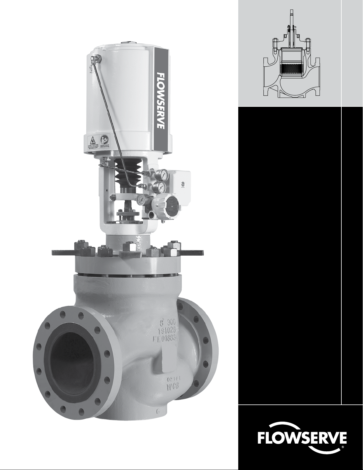
Mark 100
Installation, Operation and Maintenance Instructions
Page 2

Page 3

1 General Information
The following instructions are designed to assist in unpacking,
installing and performing maintenance as required on Flowserve
Mark 100 control valves. Product users and maintenance personnel should thoroughly review this bulletin prior to installing,
operating or performing any maintenance on the valve. Separate
Installation, Operation, and Maintenance instructions cover additional features (such as special trim, actuators, handwheels,
packing and positioners.)
To avoid possible injury to personnel or damage to valve parts,
WARNING and CAUTION notes must be strictly followed. Modifying
this product, substituting non-factory parts or using maintenance
procedures other than outlined could drastically affect performance
and be hazardous to personnel and equipment and may void existing
warranties.
WARNING: Standard industry safety practices must be ad-
c
hered to when working on this or any other process control
product. Specifically, personal protective and lifting devices
must be used as warranted.
NOTE ON FASTENERS: Selecting the proper fastener material is
the responsibility of the customer. Typically, the supplier does not
know what the valve service conditions or environment may be.
Flowserve’s standard body bolting material is B7/2H. B8 (stainless
steel) is optional for applications more than 800°F / 425°C and with
stainless steel or alloy-body valves. The customer therefore must
consider the material’s resistance to stress corrosion cracking in
addition to general corrosion. As with any mechanical equipment,
periodic inspection and maintenance is required. For more information about fastener materials, contact your Flowserve representative.
Flow Control Division
Mark 100
WARNING: indicates that death, severe personal injury and/
c
or substantial property damage can occur if proper precautions are not taken.
CAUTION: indicates that minor personal injury and/or prop-
a
erty damage can occur if proper precautions are not taken.
NOTE: indicates and provides additional technical information, which
may not be very obvious even to qualified personnel.
Compliance with other, not particularly emphasized notes, with
regard to transport, assembly, operation and maintenance and with
regard to technical documentation (e.g., in the operating instructions, product documentation or on the product itself) is essential, in
order to avoid faults, which in themselves might directly or indirectly
cause severe personal injury or property damage.
3 Unpacking
1. While unpacking the valve, check the packing list against materials received. Lists describing valve and accessories are in each
shipping container.
2. When lifting the valve from shipping container, use the lifting
lugs attached to the bonnet bolting. Take care to position lifting
straps to avoid damage to the tubing and mounted accessories.
WARNING: When lifting a valve using the lifting lugs, be
c
aware that the center of gravity may be above the lifting
point. Therefore, support must be given to prevent the
actuator from rotating. Failure to do so can cause serious injury to personnel, damage to the valve or nearby
equipment.
3. Contact your shipper immediately if there is shipping damage.
2 Terms Concerning Safety
The safety terms DANGER, WARNING, CAUTION and NOTE are used
in these instructions to highlight particular dangers and/or to provide
additional information on aspects that may not be readily apparent.
DANGER: indicates that death, severe personal injury and/or
b
substantial property damage will occur if proper precautions
are not taken.
FCD FCAIM0100-02 Mark 100 Installation, Operation and Maintenance Instructions 3
4. Should any problem arise, call your Flowserve representative.
Page 4

Flow Control Division
Mark 100
4 Installation
1. Before installing the valve, clean the line of dirt, welding chips,
scale or other foreign material.
2. Whenever possible, the valve should be installed in an upright
position. Vertical installation permits easier valve maintenance.
CAUTION: Do not insulate extension bonnets that are
a
provided for hot or cold services.
3. Be sure to provide proper overhead clearance for the actuator to
allow for disassembly of the plug from the valve body. Refer to
Table 1 for the necessary clearance needed for valve disassembly.
Table 1: Valve Disassembly Clearance
Valve Size
(inches)
6 10 254
8 13 330
10 14 356
12 16 406
14 18 457
16 20 508
18 23 584
20 25 635
24 31 787
30 37 940
inches mm
Clearance
4.1 Quick-check
Prior to start-up, check the control valve by following these steps:
1. Stroke the valve and observe the plug position indicator on the
stem clamp compared to the stroke indicator plate. The plug
should change position in a smooth, linear fashion.
NOTE: Due to excessive friction, graphite packing can cause the
plug stem to move in a jerky fashion.
2. Check for full stroke by making appropriate instrument signal
change.
3. Check all air connections for leaks.
4. Check packing box bolting for the correct adjustment. Refer to
the packing installation manual for specific details on maintaining the style of packing supplied.
CAUTION: Do not overtighten packing. This can cause
a
excessive packing wear and high stem friction that may
impede plug movement.
5. Make sure the valve fails in the correct direction in case of air
failure. This is done by turning off the air supply and observing
the failure direction.
6. After a temperature excursion has occurred, bonnet flange bolting should be retorqued to ensure bonnet gaskets do not leak.
See Table 2.
4. Double-check flow direction to be sure the valve is installed
correctly. Flow direction is indicated by the arrow attached to the
body.
5. If welding the valve into the line, use extreme care to avoid
excess heat buildup in the valve.
6. Connect the air supply and instrument signal lines. Throttling
control valves are equipped with a valve positioner. Refer to the
appropriate positioner bulletin for connections, maximum air
supplies, and maintenance instructions.
CAUTION: On valves equipped with air filters, the air
a
filter must point down to perform properly.
NOTE: In some rare cases, the air supply must be limited to
less than 150 psi (10.3 bar). This is indicated on a sticker found
near the upper air port on the actuator cylinder. An air regulator should be installed to ensure the supply pressure does not
exceed the line pressure indicated on the sticker.
Table 2: Recommended Body Bolt Torque Values
Bolt Size
(inches) ft-lb N m ft-lb N m
7
⁄8 230 312 150 203
1 350 474 220 298
1
⁄8 510 691 330 447
1
1¼ 730 990 460 624
3
⁄8 1000 1356 630 854
1
1½ 1320 1790 840 1139
5
⁄8 1710 2318 1080 1464
1
3
⁄4 2170 2942 1400 1898
1
7
⁄8 2700 3660 1700 2305
1
2 3350 4542 2100 2847
1
⁄4 4050 5491 2530 3430
2
1
⁄2 4850 6575 3010 4081
2
Carbon Steel Stainless Steel
Bolt/Stud Material
4 Mark 100 Installation, Operation and Maintenance Instructions FCD FCAIM0100-02
Page 5

Table 3: Common Packing Lubricants
Lubricant Manufacturer Temperature Range Applications, Description
Krytox 206 E.I. DuPont -5° to 550°F
-20° to 285°C
GP 460 Graphite Products Co. 32° to 1000°F
0° to 540°C
Aeroshell Grease 7 Shell Oil Co. -100° to 300°F
-75° to 150°C
Garlock Luball Garlock Inc. 32° to 500°F
0° to 260°C
Fluorinated general purpose grease; handles common liquids and gases; good
lubricity in harsh mediums; nonflammable, chemically inert; will not harm plastic
or metal parts
Graphite in petrolatum; high pressures; anti-galling, graphite remains above
600°F / 316°C
Synthetic oil-based; low-temperature applications
General purpose molybdenum disulfide lubricant economical; good in water,
steam and common chemicals; not good in harsh mediums where Krytox 206 is
recommended
Flow Control Division
Mark 100
5 Valve Maintenance
At least once every six months, check for proper operation by following the preventative maintenance steps outlined below. These
steps can be performed while the valve is in-line and, in some cases,
without interrupting service. If an internal problem is suspected,
refer to the “Valve Disassembly and Reassembly” section.
1. Look for signs of gasket leakage through the end flanges and
bonnet. Retorque flange and bonnet bolting (if required). See
Table 2.
2. Check for fluid leakage to the atmosphere through the body
drain plug, if applicable.
3. Examine the valve for damage caused by corrosive fumes or
process drippings.
4. Clean valve and repaint areas of severe oxidation.
5. Check packing box bolting for proper tightness. Refer to the
packing installation manual for specific details on maintaining
the style of packing supplied.
CAUTION: Do not overtighten packing. This can cause
a
excessive packing wear and high stem friction that may
impede stem movement.
6. If the valve is supplied with a lubricator fitting, check lubricant
supply and add lubricant if necessary. See Table 3 for common
lubricants.
NOTE: Due to excessive friction, graphite packing can cause the
plug stem to move in a jerky fashion.
WARNING: Keep hands, hair and clothing away from all
c
moving parts when operating the valve. Failure to do so
can cause serious injury.
8. Make sure positioner linkage and stem clamp are securely fastened. If the stem clamp is loose, check plug thread engagement
(refer to the “Reassembling the Actuator” section for the correct
procedure on aligning the plug with the seat.) Tighten stem
clamp nut.
9. Ensure all accessories, brackets and bolting are securely fastened.
10. If possible, remove air supply and observe actuator for correct
fail-safe action.
11. Check rubber actuator bellows for splits, cuts or wear.
12. Spray a soap solution around the cylinder actuator retaining
ring, adjusting screw and actuator stem guide to check for air
leaks through the O-rings.
13. Clean any dirt and other foreign material from the plug stem.
14. If an air filter is supplied, check and replace cartridge if
necessary.
7. If possible, stroke the valve and check for smooth, full-stroke
operation. Unsteady stem movement could indicate an internal
valve problem.
FCD FCAIM0100-02 Mark 100 Installation, Operation and Maintenance Instructions 5
Page 6

Flow Control Division
Mark 100
Figure 1: Exploded Drawing
(109,117) Gland Flange Bolting
(80) Gland Flange
(83, 87, 88, 93, 94-99)
Packing, Guides and Spacers
(108) Body Bolting
(40) Bonnet
(58) Bonnet and (56) Sleeve Gasket
(65) Pressure Balancing Seals
(50) Plug
(31) Pressure Balanced Sleeve
Parts List
Part Item
Body 1
Seat Ring* 20
Plug* 50
Plug Stem 51
Cage 30
Pressure Balanced Sleeve 31
Bonnet 40
Seat Gasket 55
Sleeve Gasket 56
Bonnet Gasket 58
Seal Types
O-ring Seal
PTFE Seal 65
Metal Multi-Seal 65
Carbon Single Seal 65
Carbon Triple Seal 65
Gland Flange 80
Gland Flange Bolting
Lower Guide 83
Upper Guide 87
Packing 88
Anti-Extrusion Spacer 93
Body Bolting 108
Packing Spacers
65
66
109,
117
94-
99
(30) Cage
(20) Seat Ring
(55) Seat Gasket
(1) Body
6 Mark 100 Installation, Operation and Maintenance Instructions FCD FCAIM0100-02
Page 7

Flow Control Division
Mark 100
6 Valve Disassembly
and Reassembly
6.1 Disassembling the Body
To disassemble the valve body, refer to Figure 1 and 2 then proceed
as follows:
WARNING: Depressurize line to atmospheric pressure and
c
drain all fluids before working on the valve. Failure to do so
can cause serious injury.
1. Fully retract the plug until the stem clamp indicator points to the
open position.
2. Remove the bonnet flange bolting and lift the actuator, bonnet
and plug out of the valve body.
WARNING: Danger exists in removing the actuator,
c
bonnet and plug, especially if PTFE plug seals are used.
The sleeve may stick to the plug and fall during disassembly, causing possible serious injury and damage
to the valve or nearby equipment. If sleeve is observed
sticking to the plug, steps 3–5 should be consulted.
Figure 2: Cutaway Drawing
CAUTION: Heavy actuators may require a hoist. Lift the
a
actuator with the yoke legs using a lifting strap and a
hoist. Great care should be taken to lift the actuator and
plug straight out of the body to avoid damage to the
plug and seat.
3. If the sleeve is observed sticking to the plug during removal,
fully extend the plug by applying air above the piston, allowing
the sleeve to remain in the body and the bonnet to rise above
the body.
4. In the gap between the top of the sleeve and the bottom of the
bonnet, place wooden blocking of equal thickness in at least
three places. The wooden blocks must not extend in far enough
that they interfere with plug movement. The plug must be allowed to stroke up to the bonnet.
5. By applying air below the piston, retract the plug until the plug
head is freed from the sleeve. Once the plug is free from the
sleeve, remove the plug and bonnet assembly from the body.
6. Lift the sleeve out of the valve body using lifting points on the
top of the sleeve.
7. Remove cage, seat ring and gaskets from the valve body.
8. Remove the plug seals from the plug head.
9. Check to see the seating surfaces on both the seat ring and
plug are free of damage to ensure tight shutoff. Make sure the
gasket surfaces on the seat ring, bonnet and body are clean and
undamaged. Inspect the pressure balanced sleeve for scratches
or other damage.
10. Loosen the stem clamp and gland flange. Remove the yoke bolts.
CAUTION: If a rubber bellows is attached to the gland
a
flange, the gland flange must be removed prior to
removing the actuator.
11. Turn the actuator off the plug and bonnet without allowing the
plug to rotate within the bonnet. Pull the plug carefully through
the packing box. Inspect the plug stem for damage or scoring.
NOTE: With air-to-close, fail-open valves, it may be necessary
to apply a small amount of air to the top of the actuator to move
the plug away from the bonnet. Otherwise, plug galling may
occur.
CAUTION: To avoid scoring guides and plug stem, fol-
a
low the above procedure exactly.
FCD FCAIM0100-02 Mark 100 Installation, Operation and Maintenance Instructions 7
Page 8

Flow Control Division
O-ring Seals
Carbon Single Seal Carbon Triple Seal
PTFE Seals Metal Multi-Seal
Mark 100
12. If the seat surfaces need remachining, both surfaces on plug
and seat ring must be reworked. The seat angle on the plug is 36
degrees and the seat ring is 33 degrees. Lapping is not necessary if proper assembly procedures are followed.
CAUTION: If remachining, protect the stem while
a
turning. Ensure concentricity of the seat surface with
the plug stem (or outside diameter of the seat ring, if
machining the seat).
13. To replace packing or change the packing box configuration,
push out packing, spacer and guides with a dowel slightly larger
than the plug stem from underneath the bonnet.
6.2 Reassembling the Body
To reassemble the valve body, refer to Figure 1 and 2 then proceed
as follows:
1. Install new bonnet and seat gaskets with the beveled edge up on
fluoropolymer gaskets.
NOTE: All gaskets should be replaced whenever the valve is
disassembled.
Triple Seals Score and break each ring as described for the
single seals. Install the inside ring first, followed by the two
outside rings with joints offset 120 degrees on all three rings.
CAUTION: Install rings starting with one end and work-
a
ing the ring carefully into place. Do not spread ring
more than necessary. Spreading the ring can cause the
ring to break.
Figure 3: Seal Designs
2. Relocate the seat ring. Carefully install the cage and then the
sleeve, taking care to ensure they installed with the correct
ends up.
3. Replace the plug seals on the plug, referring to Figure 3 and
observing the following directions:
WARNING: Gloves should be worn to help prevent the
c
hands from being burned.
PTFE Seals Heat one seal to 300°F (150°C) and slip it over the
plug into the seal groove. Thermal expansion causes the ring to
stretch, thereby making it relatively easy to slide over the plug
head.
Care must be taken to prevent the seal from rolling, rather than
sliding over the plug. The second seal can be installed following
the same procedures as the first. If for any reason the second
seal cannot be slipped onto the plug, cut the seal at approximately a 30° angle (see Figure 4) and place over the plug. Make
certain the cut seal is on the low-pressure side.
Carbon Seals
Single Seals Each seal must be scored with a sharp knife at
two places, 180 degrees apart. Holding the ring gently in a padded vise, pull gently on the ring, breaking the ring on the score
marks into two equal pieces. Install the two pieces into the plug
seal grooves with the score marks on the pressure side.
Figure 4: PTFE Seal Cutting Detail
8 Mark 100 Installation, Operation and Maintenance Instructions FCD FCAIM0100-02
Page 9

Flow Control Division
1
2
3
4
5
6
1
2
3
4
5
6
7
8
1
2
3
4
5
6
7
8
9
10
11
12
1
2
3
4
5
6
7
8
9
10
11
12
13
14
1
2
3
4
5
6
7
8
9
10
11
12
13
14
15
16
Six Bolt Pattern
Eight Bolt Pattern
1
2
3
4
5
6
7
8
9
10
Ten Bolt Pattern
Twelve Bolt Pattern Fourteen Bolt Pattern Sixteen Bolt Pattern
Mark 100
Metal Multi-Seals Install wave spring followed by four seal
rings. Stagger ring openings by at least 90 degrees. Take care
not to bend the seal rings as they are installed.
O-ring with Back-up Rings Both the O-ring and back-up rings
can stretch over plug and into place.
4. Lower the plug into the body and sleeve. Care should be taken
with the plug seals to avoid scoring or galling the sealing surface
while fitting them into the sleeve bore. With metal multi-seals
and carbon triple seals, use a ring compressor on the rings. A
suitably sized screw-type hose clamp will also serve to compress the rings for reassembly.
5. Lower the bonnet onto the plug and body, taking great care to
avoid scoring the plug stem.
6. Once the bonnet is resting squarely in the valve body, fingertighten the bonnet flange bolting.
7. Reinstall the packing and guides referring to the appropriate
packing installation manual and reinstalling new packing exactly
as shown. Make sure at least
1
⁄8" is left at the top of packing box
Figure 5: Bolt Patterns
for the top guide to enter. Different spacer lengths permit a wide
variety of packing configurations, such as twin seal and vacuumpressure packing.
WARNING: Valves with extended bonnets must not have
c
lower packing installed. Instead, lower packing rings
should be installed with the upper set. Lower packing
installed in extended bonnets will diminish the integrity
of the packing assembly.
NOTE: Graphite guide liners should be replaced each time the
valve packing is replaced. Do not rebuild the valve without new
graphite liners in the guides.
8. Replace and tighten the packing gland and bolting. Refer to the
packing installation manual for specific details on maintaining
the style of packing supplied.
9. Turn actuator back onto the body assembly, without turning the
plug inside the bonnet. Leave a
3
⁄32" to 1⁄8" (2 mm to 3 mm) gap
between the mating surfaces of the bonnet and yoke. Tighten
yoke bolting to close this gap. Firmly tighten the yoke bolting.
FCD FCAIM0100-02 Mark 100 Installation, Operation and Maintenance Instructions 9
Page 10

Flow Control Division
Mark 100
10. Using the actuator, seat the plug two or three times to center the
seat ring using pressure on the top of the actuator.
11. Tighten the body bolting, following the bolting sequence
outlined in Figure 5. Use a minimum of four steps to reach the
suggested bolt torque values shown in Table 2. Never exceed
more than 30% of the suggested bolt torque value in a single
step.
12. Slowly stroke the plug up and down to check the alignment of
the plug with the sleeve.
CAUTION: If binding or sticking is observed, discon-
a
tinue stroking the valve and reassemble using the above
steps. Failure to do so could cause serious valve damage. Contact your Flowserve representative if binding
cannot be resolved.
13. Perform a Quick Check as described in section 4.1.
Troubleshooting Chart
Problem Possible Cause Corrective Action
Stem motion
impeded
Excessive
leakage
Inadequate flow 1. Improper plug adjustment, limiting stroke. 1. Refer to step 9 of “Reassembling the Body” section for correct
Plug slams 1. Incorrect plug adjustment allowing improper cushion of air
Valve does not
fail in correct
position
1. Overtightened packing. 1. Refer to proper maintenance instructions and readjust.
2. Service temperature is beyond operating limits of trim design. 2. Reconfirm service conditions and contact factory.
3. Inadequate air supply. 3. Check for leaks in air supply or instrument signal system;
4. Malfunctioning positioner. 4. Refer to positioner maintenance instructions.
1. Improperly tightened bonnet flange bolting. 1. Refer to step 11 of “Reassembling the Body” section for correct
2. Worn or damaged seat ring. 2. Disassemble valve and replace or repair seat ring.
3. Worn or damaged seat or bonnet gasket. 3. Disassemble and replace gaskets.
4. Inadequate actuator thrust. 4. Check for adequate air supply to actuator; if air supply is
5. Incorrectly adjusted plug. 5. Refer to step 9 of “Reassembling the Body” section for correct
6. Improper flow direction. 6. Refer to original specifications or contact factory.
7. Improper handwheel adjustment; handwheel acting as a limitstop.
2. Malfunctioning positioner. 2. Refer to positioner maintenance instructions.
3. Service conditions exceed trim design capacity. 3. Verify service conditions and consult factory.
between actuator piston and yoke.
2. Inadequate air supply. 2. Check air supply to actuator; repair leaks and remove any
3. Trim sized too large for flow rate. 3. Install reduced trim.
1. Incorrect flow direction. 1. Reconfirm direction and, if necessary, correct flow direction
tighten loose connections and replace leaky lines.
tightening procedure.
adequate, reconfirm service conditions and contact factory.
plug adjustment.
7. Adjust handwheel until plug seats properly.
plug adjustment.
1. Refer to step 9 of “Reassembling the Body” section for correct
plug adjustment.
restrictions in supply line.
through valve.
10 Mark 100 Installation, Operation and Maintenance Instructions FCD FCAIM0100-02
Page 11

Page 12

This page is intentionally blank.
Flow Control Division
Mark 100
Flowserve Corporation has established industry leadership in the design and manufacture of its products. When properly selected, this Flowserve product is designed to perform
its intended function safely during its useful life. However, the purchaser or user of Flowserve products should be aware that Flowserve products might be used in numerous
applications under a wide variety of industrial service conditions. Although Flowserve can (and often does) provide general guidelines, it cannot provide specific data and warnings
for all possible applications. The purchaser/user must therefore assume the ultimate responsibility for the proper sizing and selection, installation, operation, and maintenance of
Flowserve products. The purchaser/user should read and understand the Installation Operation Maintenance (IOM) instructions included with the product, and train its employees
and contractors in the safe use of Flowserve products in connection with the specific application.
While the information and specifications contained in this literature are believed to be accurate, they are supplied for informative purposes only and should not be considered
certified or as a guarantee of satisfactory results by reliance thereon. Nothing contained herein is to be construed as a warranty or guarantee, express or implied, regarding any
matter with respect to this product. Because Flowserve is continually improving and upgrading its product design, the specifications, dimensions and information contained herein
are subject to change without notice. Should any question arise concerning these provisions, the purchaser/user should contact Flowserve Corporation at any one of its worldwide
operations or offices.
For more information about Flowserve Corporation, visit www.flowserve.com or call USA 1-800-225-6989.
FLOWSERVE CORPORATION
FLOW CONTROL DIVISION
1350 N. Mt. Springs Parkway
Springville, UT 84663
Phone: 801-489-8611
Fax: 801-489-3719
© 2009 Flowserve Corporation, Irving, Texas, USA. Flowserve is a registered trademark of Flowserve Corporation. FCD FCAIM0100-01 Printed in USA.
 Loading...