

Page 1
Edward Valves
Maintenance Manual for Edward
Equiwedge
™
Gate Valves
V-378 R1
Page 2

2
Flow Control Division
Edward Valves
Table of Contents
Introduction and Scope .........................3
Gate Valve Figure Numbers ...................3
Description of Equiwedge
Gate Valve Types...............................4
Type I..................................................4
Type II..............................................4-5
Type III................................................5
Type IV................................................5
Type V.................................................5
Service Problems ..................................6
Packing Chamber Leak.......................6
Packing Recommendations..................6
Pressure Seal Gasket Leak ..................7
Pressure Seal Leak.............................7
Gate and Seat Leakage......................8
Body or Bonnet Wall Leak ..................8
Lubrication........................................8
Repair Procedures.................................9
Valve Body Repairs.– Body
Bore Gasket Seal Area Repairs.........9
Body Wall Repairs...........................10
Body Guide Repairs.........................10
Seat Repairs....................................10
Gate Repairs ...................................11
Bonnet Repairs ................................11
Backseat.........................................11
Porosity in Bonnet............................12
Stem Repairs...................................12
Field Repair Equipment.....................12
Disassembly Procedure for
Equiwedge Gate Valves....................13
Disassembly Procedure for Bonnet Types,
Area 3
Type I .............................................14
Type II............................................15
Type III ...........................................16
Type IV & V ....................................17
Reassembly Procedures for Equiwedge
Gate Valves ....................................18
Exploded View...................................19
Reassembly Instructions........................20
Handwheel Actuated Valves ..............20
Tapered Roller Bearing
Preload Instructions ........................21
Reassembly Instructions for
Valves with Composite Pressure
Seal Gaskets Only.........................23
Type I Reassembly............................24
Type II Reassembly...........................25
Type III Reassembly ..........................26
Type IV & V Reassembly...................26
Appendix A
Procedure for Removing Manual
& Electric Actuators...................28-29
Appendix B
Valve Tools Available for Rental.........30
Terms and Conditions ..........................31
Contact Information ............................32
TABLES
Table 1 Gland Bolt Torques.................7
Table 2 Bonnet/Cover Bolt/
Nut Pull-up Torques.................7
Table 3 Welding Rod
Recommendations ................22
Table 4 Dimensions for
Bearing Preload Washer.......22
Table 5 Bearing Retainer
Preload Torque ....................22
Table 5A ..........................................22
Table 6 Bearing Retainer
Final Torque ........................22
Table 6A ..........................................22
Table 7 Composite Gasket
Bonnet/Cover Bolt/Nut
Pull-Up Torques ....................23
Page 3
3
Flow Control Division
Edward Valves
Introduction and Scope
Introduction
This manual has been prepared to serve as
a guide for maintenance of Edward
Equiwedge gate valves, all of which
feature the pressure seal bonnet joint
construction. Although rigid metallurgical,
non-destructive examination, physical and
visual inspection is standard procedure for
Edward Valves products, it is inevitable
that some valves, after a period of time,
will require repairs. This manual will assist
you in restoring the valve to good working
condition with a minimum of time and
expense.
Scope
Before starting any repairs, it will be
helpful to have some understanding of the
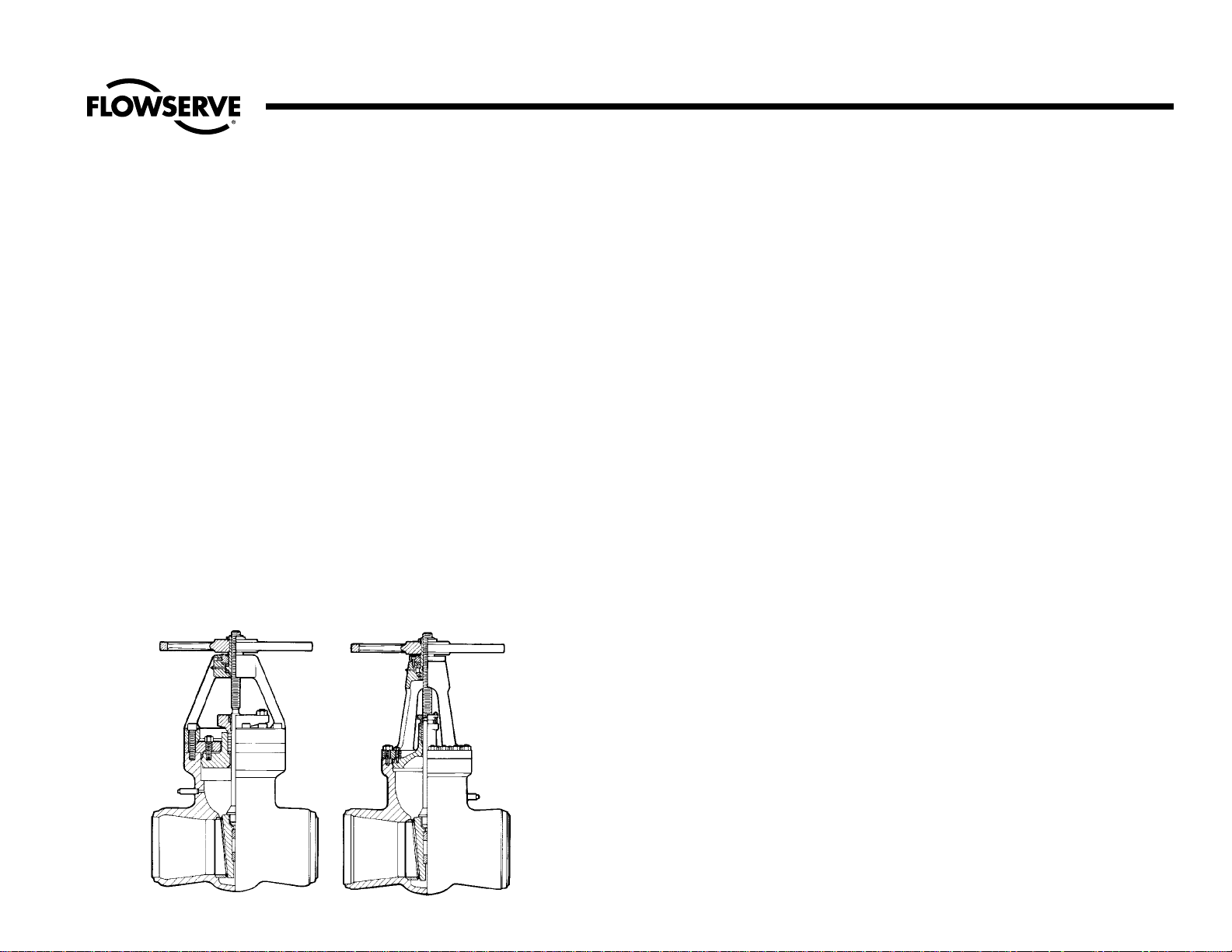
valve’s physical construction. Consequently,
the five basic types of pressure seal construction are discussed and illustrated first.
All Equiwedge gate valves employ one of
these five basic types.
The next major section of this manual
discusses the more common service
problems, and explains the reason for
certain failures. The reason for the problem
should be understood before work is actually started.
Then, the procedure to be followed in making the repair is explained. This section
includes normal valve maintenance as well
as major valve repairs. Field repair equipment available from Edward Valves is
described and illustrated. Valve lubrication
and welding rod recommendations are
also included. These procedures should be
adequate for almost any Equiwedge gate
valve repair or maintenance problem that
may arise.
Following is a section describing the
disassembly procedure for the various
valve components; for example, manual
handwheel, manual geared actuators or
electric actuators, valve yokes, and the five
basic bonnet types. It is very important that
this manual be studied before any
disassembly work is done to avoid needless work and loss of time by selecting the
improper procedures.
The last sections include reassembly instructions and available maintenance equipment and information on the various types
of actuators, both manual and electrical.
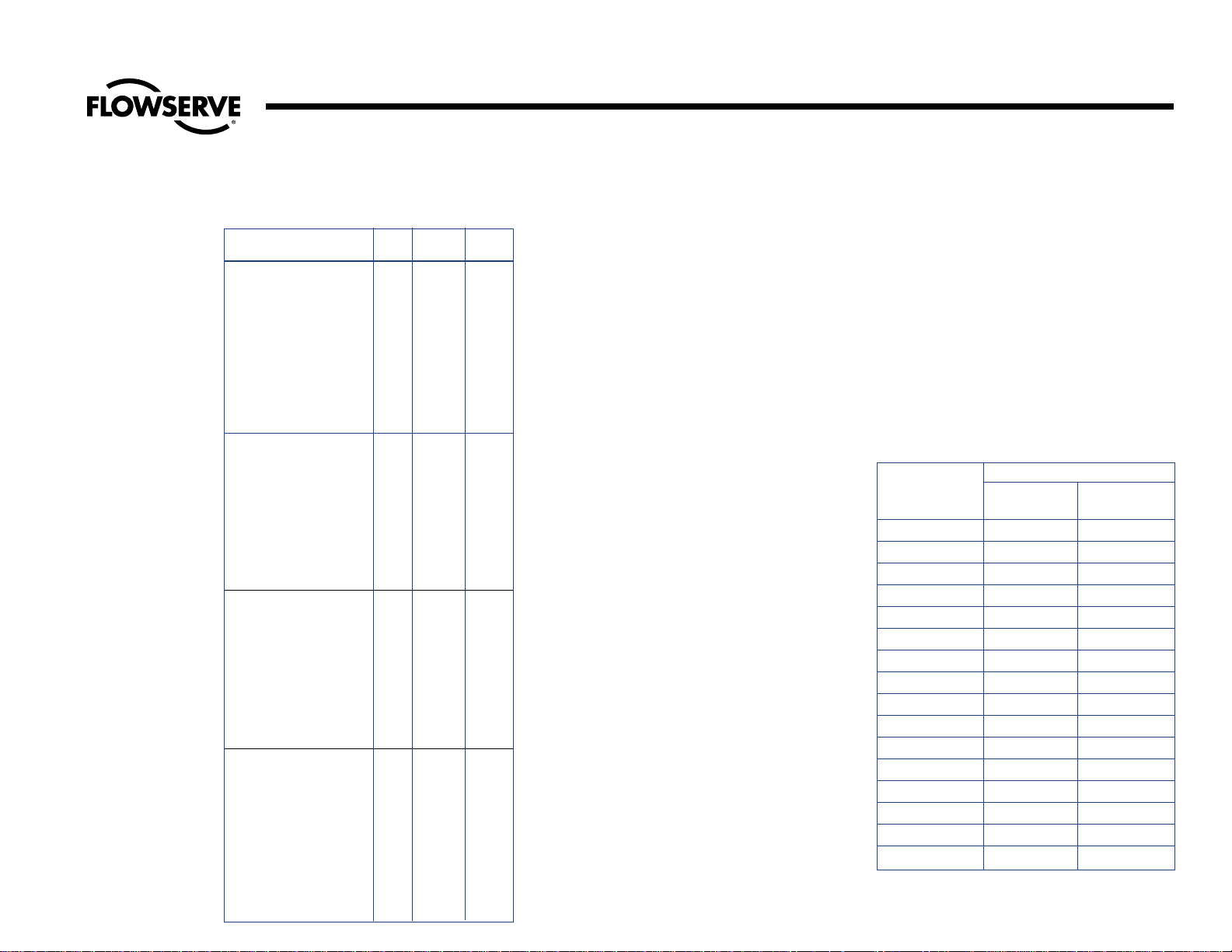
Figure No. Class Pressure Seal Type Size
1611-1611Y 600 I & II 21⁄
2 to 28
1711Y Special Class 600 I & II 21⁄2 to 28
1911-1911Y 900 III, IV, & V 21⁄
2 to 28
14311Y Special Class 900 III, IV, & V 21⁄
2 to 28
11511-11511Y 1500 III, IV, & V 21⁄2 to 24
12011Y Special Class 1500 III, IV, & V 21⁄2 to 24
12511-12511Y 2500 III, IV, & V 21⁄2 to 24
14411Y Special Class 2500 III, IV, & V 21⁄2 to 24
Gate Valve Figure Numbers Described in this Manual
Page 4
4
Flow Control Division
Edward Valves
Description of Equiwedge Gate Valve Types
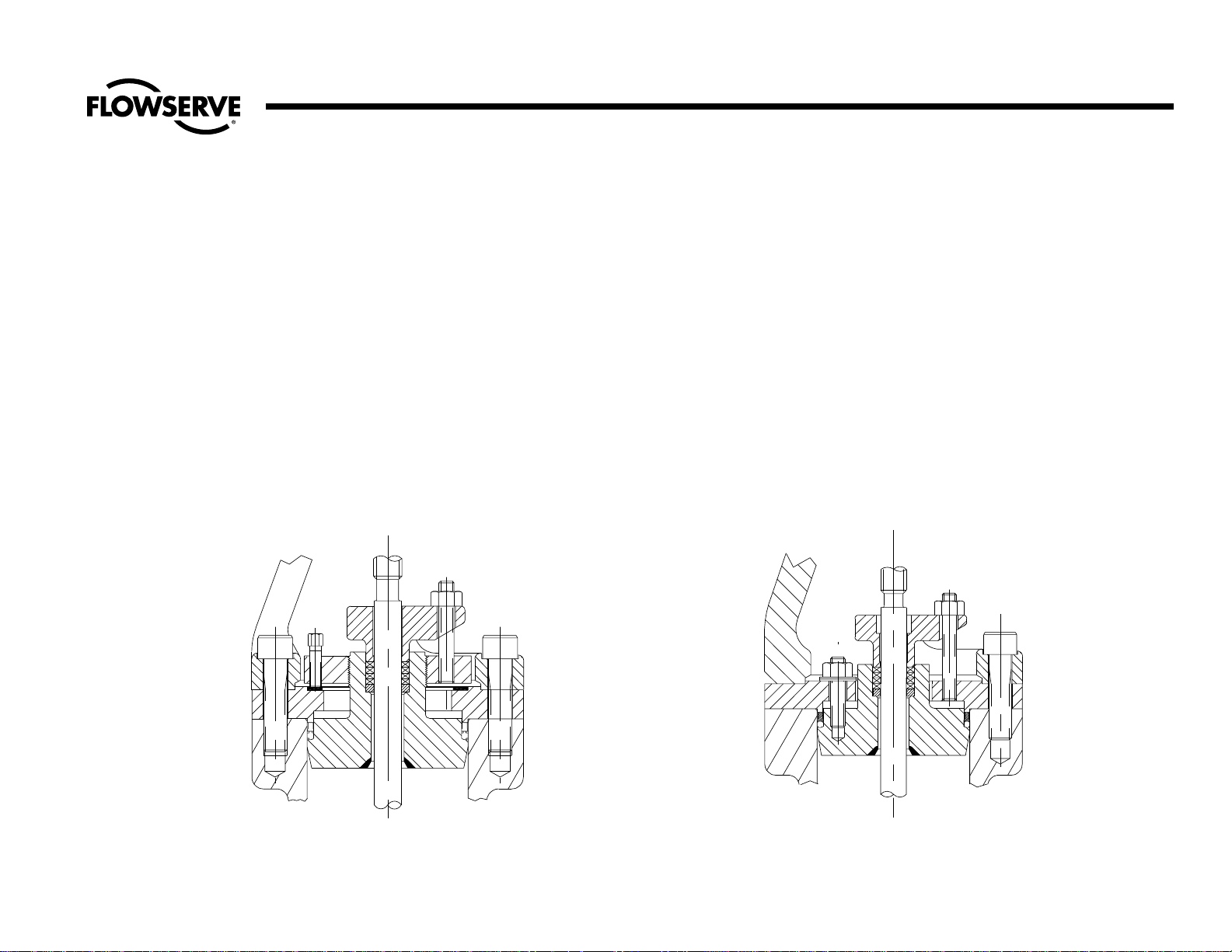
Type I is a flanged yoke design with a
separate gasket retainer ring, both of
which are held to the body by cap
screws. The bonnet retainer is screwed
onto the bonnet and cap screws are
screwed down on top of the body to force
the bonnet into contact with the gasket.
See illustration No. 1.
Type II is a flanged yoke design with or
without a separate bonnet retainer ring,
both of which are held on the body by
cap screws or studs and nuts. The bonnet
is pulled up into contact with the gasket
with studs and hex nuts. See illustrations
Nos. 2A and 2B, pgs. 4 and 5.
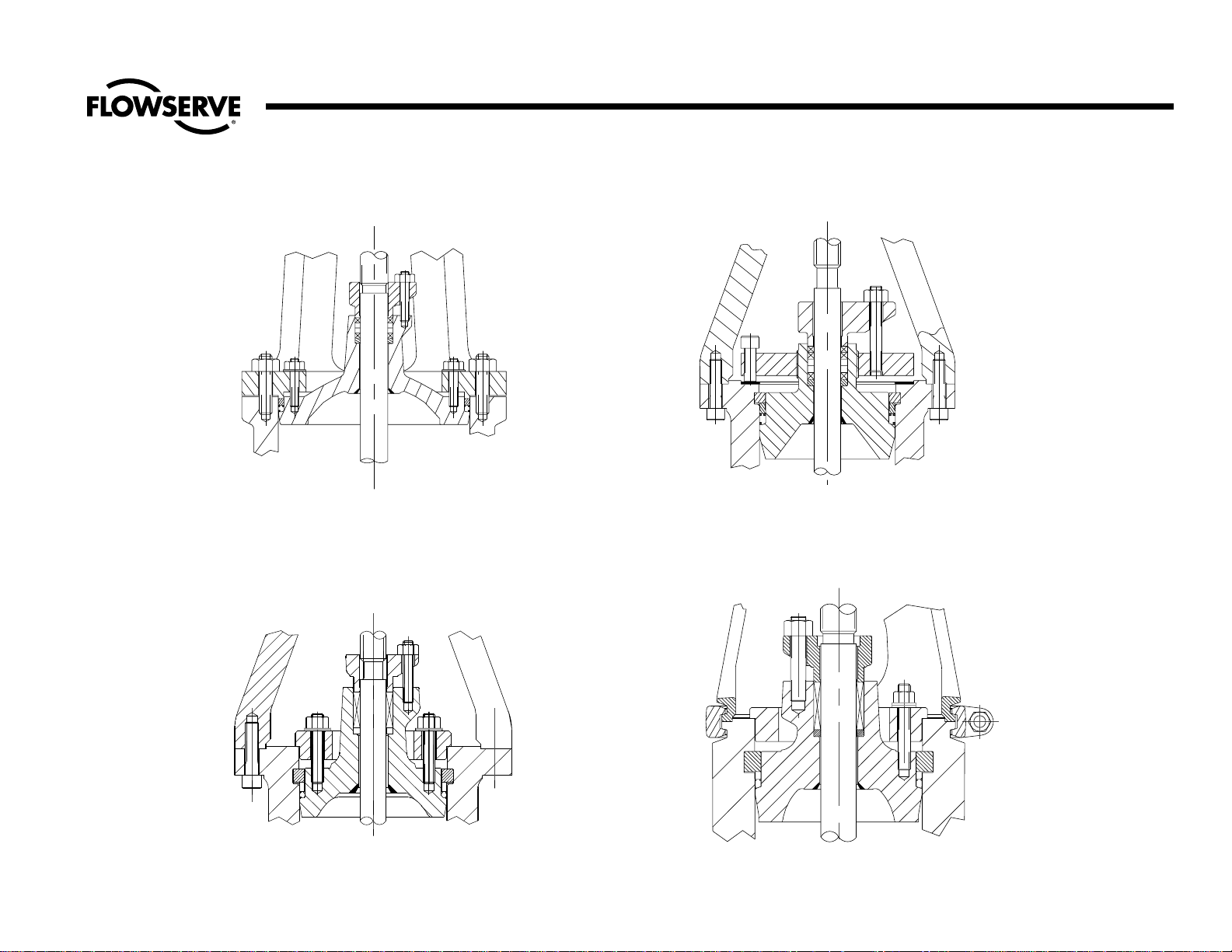
Type III is a wishbone yoke design bolted
to the body. It has a segmental retaining
ring, spacer ring and a screwed on
bonnet retainer equipped with push down
bolts to pull the bonnet up into contact
with the gasket. See illustration No. 3,
pg. 5.
Type IV is a wishbone yoke designed bolted to the body. It has a segmental
retaining ring, spacer ring and separate
bonnet retainer with pull up studs screwed
into the bonnet to contact the gasket. See
illustration No.4, pg. 5.
Type V has a yoke lock ring connection to
the body with a segmented ring, gasket
retainer and a separate bonnet retainer
with studs screwed into the bonnet to pull
up the bonnet against the gasket. See
illustration No. 5, pg. 5.
Illustration No. 1 Illustration No. 2A
Size 2-1/2 & 3 - Figure 1611 and 1611Y Size 4” -Figure 1611 and 1611Y
Size 2-1/2 & 3 - Figure 1711Y Size 4” - Figure 1711Y
Valve Type I Valve Type IIA
Page 5
5
Flow Control Division
Edward Valves
Description of Equiwedge Gate Valve Types (cont.)
Illustration No. 2B
Size 6 - 28 - Figure 1611 and 1611Y
Size 6 - 28 - Figure 1711Y
NOTE: Size 6 and 8 valves are wishbone yoke design with flange.
Valve Type IIB
Illustration No. 4
Size 4 - 8 - Figure 1911-1911Y-14311Y
Size 4 - 8 - Figure 11511-11511Y-12011Y
Size 4 - 8 - Figure 12511-12511Y-14411Y
Valve Type IV
Illustration No. 3
Size 2-1/2 - 3 - Figure 1911-1911Y-14311Y
Size 2-1/2 - 3 - Figure 11511-11511Y-12011Y
Size 2-1/2 - 3 - Figure 12511-12511Y-14411Y
Valve Type III
Illustration No. 5
Size 10 - 28 - Figure 1911-1911Y-14311Y
Size 10 - 24 - Figure 11511-11511Y-12011Y
Size 10 - 24 - Figure 12511-12511Y-14411Y
Valve Type V
Page 6

6
Flow Control Division
Edward Valves
Service Problems
Packing Chamber Leak
Where moisture appears or actual dripping
occurs at the packing chamber around the
stem, gland or gland flange which cannot
be eliminated by re-torquing the gland bolt
the following points should be considered.
1. The packing may have become hard.
Replace the packing.
2. Gland travel has been fully taken up.
Repack with new packing.
3. The wrong packing is being used.
See packing recommendations shown
on this page.
4. A stem should be replaced when it
has become deeply scratched,
burred, or otherwise mutilated from
careless handling, or where the stem
has worn, tapered or has been bent.
5. The gaps in the rings of split packing
have not been staggered around the
stem. They should be inserted in this
manner.
6. The packing gland may be binding
against the packing chamber or stem
and does not compress the packing
properly. Make certain the gland fits
the packing chamber and is tightened down equally on each side.
Packing Recommendations
Edward valves are packed with all-purpose
with packing sets. This is a combination of
packing using braided rings at the top and
bottom in the packing chamber and flexible graphite packing in the center section.
Packing gland should be tightened down
enough to prevent leakage but not enough
to develop excessive operating torque.
When the gland has advanced approximately half way into the packing chamber,
it is recommended that additional packing
rings be added. To obtain best results,
the stem should be thoroughly cleaned.
Replacement packing should be the same
as that originally furnished.
We recommend that replacement packing
be purchased from Edward Valves to
assure packing with the proper density and
corrosion inhibitors is always used.
IMPORTANT:
Long service life from modern graphitic
packing requires that adequate preloads
be applied when repacking.
1. All parts should be clean and not
scored or pitted, especially the stem.
2. The valve internal parts and bonnet
should be assembled prior to
installing the packing.
3. Position split packing rings with the
ends of adjacent rings rotated 90°.
4. Install in the following sequence:
Bottom Ring – Braided Ring
Center Rings – Die formed
expanded graphite
Top Ring – Braided Ring
5. Clean and lubricate the gland eyebolts.
6. Carefully seat each individual packing ring before adding the next ring.
7. Apply the recommended torque to
the gland nuts evenly without cocking
the gland. See Table 1, pg. 7, for
recommended torques.
8. Tighten the nuts to the initial values
shown, then loosen and re-tighten to
the final torque.
9. Stroke the valve, then re-check the
gland nut torques.
Note: The torque values given are for
sealing full rated pressure. For line pressures less than the full CWP rating of the
valve, the final torques may be reduced by
the ratio of P
actual
/CWP down to a mini-
mum of P
actual
= 1500 psig. This will
reduce packing drag and extend packing
life.
Page 7
Flow Control Division
Edward Valves
Service Problems (cont.)
Pressure Seal Gasket Leak
Edward valves have been produced with
two types of pressure seal gasket: Earlier
valves had metal gaskets, while later
designs have composite expanded graphite
gaskets. The valves with composite gaskets
can be identified by a “B” prefix on the figure number. Assembly and disassembly of
the two gasket types are essentially the
same except the composite gasket designs
have belleville spring washers under the
nuts (or capscrews) of the pull-up bolting,
and the tightening torque requirements for
the pull-up bolting are different.
To guard against leakage, the bolts should
he kept tightened at all times.
A torque wrench should be used for tightening the bonnet or cover retainer stud nuts or
capscrews which are used to pre-load the
pressure seal gasket.
All nuts/capscrews should be tightened in
an alternating star pattern to insure even
tightening.
The bolting should be tightened to the
torque values shown in Table 2 while the
valve is under full line pressure.
Pressure Seal Leak
Should the leak fail to stop after tightening,
it must be concluded that there is an imperfect pressure seal, and the valve will have
to be opened for examination.
(Note: Regardless of the cause of failure,
opened pressure-seal bonnets should
always be reassembled with a new gasket.
These are available from stock via Air
Express from Raleigh, North Carolina.)
Such a leak may result from any of the
following causes:
1. Incomplete Seal Between Bonnet and
Gasket. An incomplete seal around
the gasket seating surface of the bonnet (or cover on check valves) may be
caused by corrosion, dirt, chips, or
other foreign matter on the mating surfaces of the sealing angle.
2. Incomplete Seal Between Body I.D.
and Gasket. An incomplete seal in the
INITIAL FINAL
FIGURE NUMBERS SIZE TORQUE TORQUE
2.5 26 8
326 8
426 8
629 8
844 13
1611, 1611Y, 1711Y 10 67 19
12 72 21
14 76 22
16 95 27
18 121 35
20 127 37
24 156 45
28 221 64
2.5 26 11
326 11
426 11
644 19
864 28
1911, 1911Y, 14311Y 10 72 31
12 107 46
14 151 65
16 159 69
18 167 72
20 208 90
24 193 84
2.5 26 19
326 11
429 21
648 35
890 65
11511, 11511Y, 12011Y 10 151 109
12 223 161
14 242 175
16 343 247
18 353 255
20 378 273
24 268 193
2.5 26 26
326 26
429 29
6 101 101
8 133 133
10 155 155
12511, 12511Y, 14411Y 12 311 311
14 199 199
16 442 442
18 311 311
20 503 503
22 663 663
24 806 806
TABLE 1
GLAND BOLT TORQUES, FT-LBS
CLASS 300 & 600 VALVES
TABLE 2
BONNET/COVER BOLT/NUT PULL-UP
TORQUES
(WITH VALVE UNDER PRESSURE)
REQUIRED TORQUE, FT-LBS
BOLT SIZE METAL COMPOSITE
GASKET GASKET
3/8 18 5
7/16 30 5
1/2 45 7
9/16 68 10
5/8 90 15
3/4 150 25
7/8 240 35
1 370 55
1 1/8 533 80
1 1/4 750 110
1 3/8 1020 150
1 1/2 1200 170
1 5/8 1650 230
1 3/4 2250 320
1 7/8 3000 420
2 3300 460
7
Page 8

8
Flow Control Division
Edward Valves
Service Problems (cont.)
area of the gasket and body I.D. contact
may be caused by surface imperfections
in the body wall in the form of pin holes,
extended cracks, or indentations where
the metal has failed sometime after valve
installation and use. Such imperfections
may be surface indications deeper flaws
in the body casting which may cause a
by-pass around the pressure seal.
Gate and Seat Leakage
A leak existing at the seat and gate of a
properly closed valve might be indicated
by one of the following: a definite pressure
loss in the high pressure side of the valve;
continued flow through an inspection drain
on the low pressure side; or, in hot lines, a
downstream pipe that remains hot beyond
the usual length of time and conductivity
range. First, try opening the valve slightly
to flush any foreign material from the seating surfaces and then fully close the valve.
If this doesn’t stop the leakage, then one or
more of the following may be the cause:
1. Foreign material has been imbedded
into the seating surfaces preventing a
seal.
2. Foreign material has scratched or cut
the seating surface.
3. An obstruction such as a tool or other
foreign material has been lodged across
or between the seats and preventing the
gate from closing.
4. The valve seat has been steam or water
cut by not fully closing the valve during
a previous operation.
If the valve cannot be isolated and
repaired as soon as possible, schedule the
work to be done at the next outage.
Body or Bonnet Wall Leak
This is a leak through the pressure containing parts of the valve. A leak occurring
through the bonnet should be readily
detectable because of the lack of insulation. On the body, because of the heavy
insulation, a small leak may go unnoticed
for a time on a hot line because the piping
evaporates the leakage.
Lubrication
In order to obtain long service life and
maximum reliability, valves require periodic lubrication of the bearings and stem
threads the same as for any machinery
with rotating parts.
All handwheel actuated Equiwedge gate
valves are equipped with low friction bearings, needle bearings in the smaller sizes
and tapered roller bearings in the larger
sizes. These valves have a lube fitting for
convenient relubrication. Both the stem
threads and the bearings can be relubed
through this fitting. In addition, it is advisable to clean the stem first while in the
open position and apply fresh grease to
the threads, then repeat while in the closed
position.
For valves that are operated infrequently,
relubrication at least once a year is recommended. The recommended lubricant for
both bearings and stem threads is Rycon
EP 2, manufactured by the American Oil
Company. This is an extreme pressure,
temperature lubricant of high quality. Use
of other lubricants should be avoided.
For valves that are operated frequently, the
lubricant should be replenished at both the
bearings and stem threads every three
months or at shorter intervals depending
on the severity of the service.
Page 9

9
Flow Control Division
Edward Valves
VALVE BODY REPAIRS
Body Bore Gasket Seal Area Repair
(Valves with metal gasket only)
Class 600 Equiwedge gate valves have
the seal area for the pressure seal just
below the top of the body bore. The seal
surface is inlaid with 18-8 stainless steel
on all valves size 16 and larger.
Class 900 and higher Equiwedge gate
valves have the seal area just below the
gasket retainer groove. The seal surface is
inlaid with 18-8 stainless steel on all valves
in these pressure classes.
The seal area, whether inlaid or not, must
be smooth, round and without any appreciable taper. Upon normal disassembly of
the valve the gasket may leave some vertical score marks when withdrawn.
If the depth of defects are .010” or less,
the seal area can be honed using a
portable Sunnen Hone. This device is
adjustable for different bore sizes and can
be operated by one man using a portable
electric drill of 1/2” to 3/4” capacity.
When the defects are greater than .010”,
welding will be required to cut down the
repair time.
First make visual inspection all around this
area, noting, if possible, where flaws may
occur. Next wash the area with a suitable
solvent, drying with clean rags and, if necessary, polishing with a fine grade of
emery cloth to remove any undesirable
scale or foreign matter which may be been
deposited on the area suspected of having
flaws. Use a dye penetrant test if cracks
are suspected.
Where it is necessary to repair the body
inlay by welding, note the following:
1. Prior to any cutting or welding oper-
ations being performed on the valve,
it is necessary that adequate seat
joint protection be provided and
some means of insurance against
getting chips, weld spatter or other
foreign matter into the pipe line if
the valve is permanently mounted. A
round piece of sheet metal placed in
the bore down to the shoulder above
the guide grooves and taped in
place will protect the guide surfaces
and seats.
2. Chip out the defective area in the
body, being careful to remove the
affected portion to its end, inside the
casting, and to thoroughly clean it
away.
3. With a small hand grinder, grind the
chipped area smooth.
4. Preheat an area large enough
around the imperfection so that during the entire welding operation heat
will be retained at approximately
400 degrees Fahrenheit.
5. Use a stainless steel inlay selected
from either 18-8 stainless steel rod,
Harstain 18-8, Stainweld “K” 18-3,
Stainweld 18-8 or equivalent.
6. Lay the weld in thin, even layers,
peening each layer before proceeding with the next, and being careful
to maintain a temperature above
400 degrees Fahrenheit in the area
being repaired. Peening the bead
actually stretches it and counteracts
its tendency to contract and shrink as
it cools. The last layer of weld must
overlap onto the sound metal to
insure a weld without an undercut at
the edges. The overlapping should
be done along this edge by using a
welding rod of 1/8” maximum diameter. The last layer should bring the
height of the welded area up to
1/16” above the original surface, as
checked with a straight edge along
the body bore.
For this type of weld repair, it is recommended that the last layer be
pounded while still hot with the flat
face of the hammer. Thermal stress
relieving is not recommended.
With a hand grinder, rough grind
the welded surface to within about
.010” of the finished surface. A simple template cut from thin sheet
metal and having the same arc as
the body bore diameter, and straight
edge laid along the body bore can
be used as a guide. A final cut then
can be made, using a fixture similar
to the one shown in Illustration No.
9, pg. 15. Final finishing can be
done with the adjustable Sunnen
hone described on this page.
After removing all the dirt, chips,
slag, spatter, and grinding dust from
the body, the bore should be polished with fine emery cloth and then
thoroughly cleaned before reassembly of the valve.
Repair Procedures
Page 10
10
Flow Control Division
Edward Valves
It is best that a new pressure-seal
gasket be used upon reassembly.
Body Wall Repairs
There are five basic steps in repairing a
casting defect:
1. Cut out to sound metal. Attempting to
weld over the defect will only leave a
notch that may re-introduce the defect.
Cutting may be done by chipping,
grinding or flame gouging. The amount
of metal removed should be held to a
minimum to avoid distortion during subsequent welding.
2. Preheat, using the minimum temperature
specified by the material specification
and/or the design code. Use at least
400F on WC9 or C5 material, 300F
on WC6. Although cast carbon steels
such as WCB or WCC do not require
preheat, it may be advantageous to
remove any moisture or other contaminants from the area to be welded. This
may also identify any leak paths. There
are also disadvantages to preheat,
especially localized preheat, that must
be considered when working in areas
of the casting with finish machined
dimensions. Distortion may result in
more damaging problems than those
concerns created by the original defect.
Lower preheats and the control of interpass temperature are two methods used
to minimize distortion.
3. Welding should be done by qualified
welders, using qualified procedures and
weld material of a chemistry matching
the casting (see Table 3 for welding rod
recommendations). The final weld
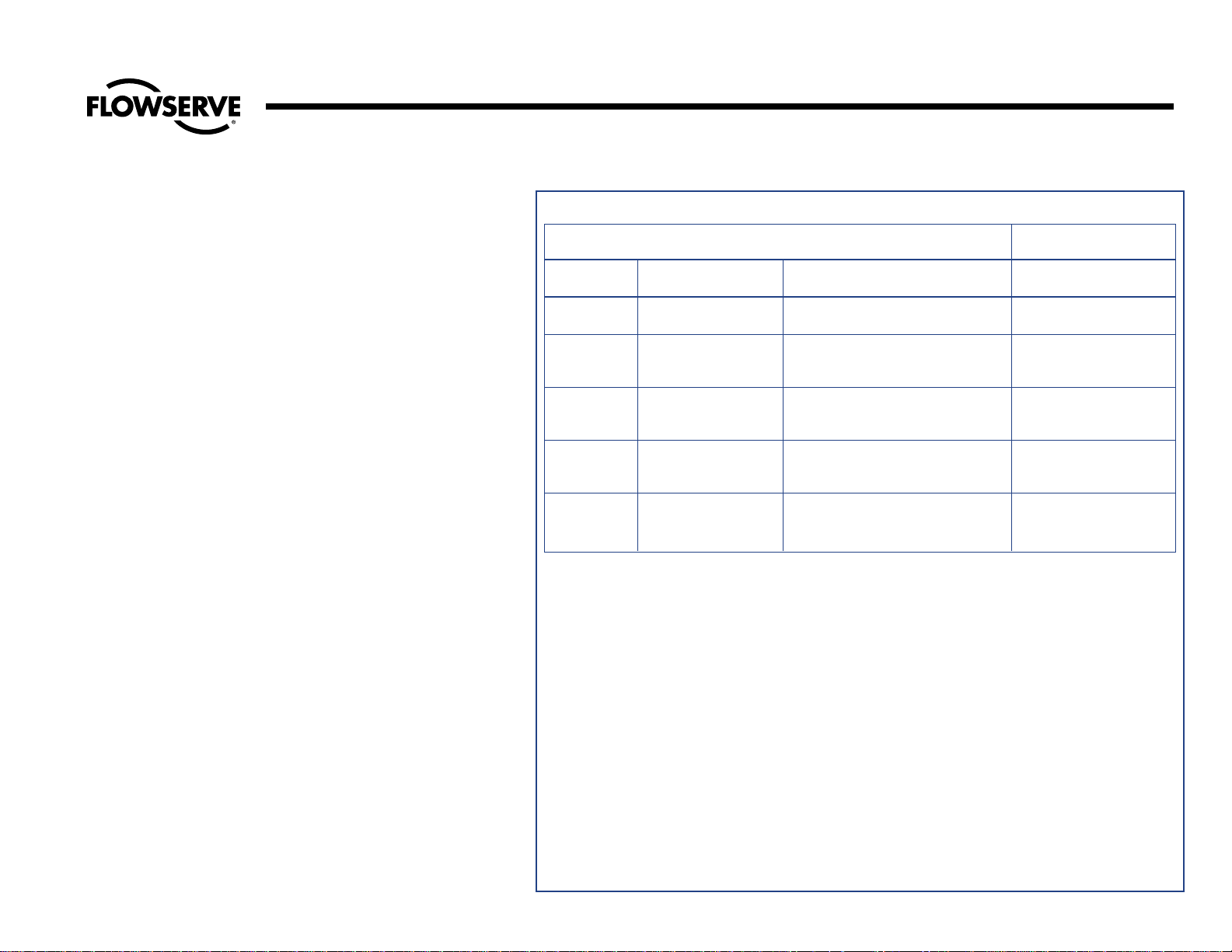
TABLE 3 – WELDING ROD RECOMMENDATIONS
MATERIAL TO BE WELDED
WELD ROD
RECOMMENDATIONS
ASME IX
Material ASTM Grade AWS Classification
P-Numbers
P-1 Carbon Steel 1. ASTM A216, Grade WCB AWS 5.1
2. ASTM A105 E7018
P-4 1-1/4% Chromium, 1. ASTM A217, Grade WC6 AWS 5.5
1/2% Molybdenum 2. ASTM A182, Grade F11 E8018-B2
Low Alloy Steel
P-5 2-1/4 Chromium, 1. ASTM A217, Grade WC9 AWS 5.5
1% Molybdenum 2. ASTM A182, Grade F22 E9018-B3
Low-Alloy Steel
P-8 18% Chromium, 1. ASTM A351, Grade CF8M AWS 5.4
8% Nickel 2. ASTM A182, Grade F316 E316
Stainless Steel
P-8 18% Chromium, 1. ASTM A351, Grade CF8C AWS 5.4
8% Nickel 2. ASTM A182, Grade F347 E347
Stainless Steel
Repair Procedures (cont.)
WELDING EDWARD VALVES IN-LINE
When welding a valve in line, the installer
should apply the specific technical rules
imposed by the jurisdictional authority of the
area where the valve is installed, In the
absence of such rules, following are
suggested practices for welding Edward
Valves in line:
1. Welding should be done using procedures
and personnel qualified in accordance
with ASME Section IX. Rules for preheat
and postheat are stated in Chapter V of
ASME B31.1 (Power Piping).
2. The valve should be welded in line, one
end at a time, in a closed position
(approximately a half-turn after the seat in
the body comes in contact with the disk).
This is suggested to preclude warpage
between seating surfaces caused by temperature induced stresses during welding
or subsequent heat treat. It also protects
the seat from weld spatter that might coat
the lapped seat and disk. When postweld
heat treat is required, each weld end
should be heat treated one at a time, to
minimize impact of heat on valve internals.
Do not heat treat an Edward Valve with a
piping attached as a unit in a furnace, as
warpage of parts may occur. After welding, open the valve and flush the line to
clean out all foreign matter.
Page 11
11
Flow Control Division
Edward Valves
should be blended into the contour of
the casting.
4. Stress relieving is generally recommended. Decisions to not stress relieve should
factor in piping code rules. The temperatures must be based on material specification and piping code recommendations. Again, since temperatures are
much higher than those experienced in
welding, there are also disadvantages
that must be considered. Distortion may
result in more damaging problems.
Lower temperature postweld heat treatment is sometimes an option for carbon
steels.
5. The final weld should receive any needed nondestructive testing. This should
include a visual examination and liquid
penetrant or magnetic particle examination. Some major weld repairs could
even mandate radiography to ensure a
sound weld.
Body Guide Repairs
The body guide grooves guide the gate
through about 95% of the valve stroke and
allow only 5% of the valve stroke to thrust
against the seating surfaces. It is important
that the side faces of the groove be smooth
and free of gouges and burrs. A flat file
can be used to remove any burrs and
raised edges.
Seat Repairs
The seats in a gate valve may require
repair when the seating surfaces allow
fluid to pass. This may be due to erosion
of the surfaces caused by not closing the
valve tightly or seating on foreign material.
Verification of such conditions may be
obtained by a seat blueing test or by close
visual examination.
To correct these conditions seat refinishing
will be necessary. A Dexter gate valve
refinishing fixture will speed up repairs.
See Appendix B for a discussion on use of
the Dexter equipment.
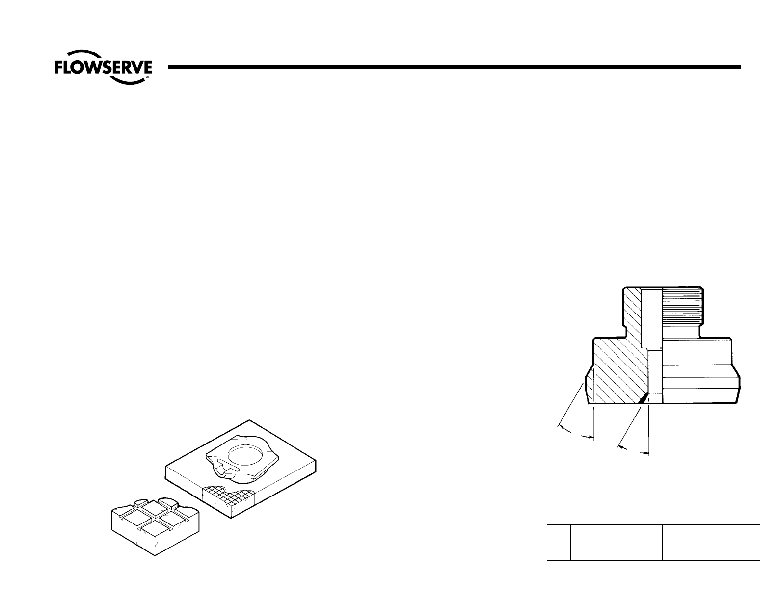
Gate Repairs
Gate repairs to the seating surface can be
done on a flat cast iron lapping plate. The
lapping plate should be large enough so
that the seating surface contacts the full
diameter with sufficient additional surface
allowing the gate to be pushed at least
1/3 of its diameter in any direction.
Clover compound “A”, Norton 320 mixed
with olive or sperm oil, or for rough lapping, Carborundum H20 may be used.
See illustration No. 6A.
Gate guide repairs can be done by rubbing the surface with a square steel block
wrapped with emery cloth.
Bonnet Repairs
The valve bonnet provides several functions
as follows: closure of the pressure vessel, a
packing chamber to seal the stem, a backseat area sealed with the stem so the valve
can be repacked under pressure, and a
sealing arrangement to prevent leakage to
the atmosphere.
Equiwedge gate valves with metal pressure
seal gaskets have a number of different
angles machined on the bonnet to accommodate the pressure seal gasket. These
angles are shown in illustration No. 6B.
Repair Procedures (cont.)
Illustration No. 6A
Valve Gate on
Lapping Plate
A°
±0.25°
30°
Pressure Seal Bonnet Angles
(Valves with metal gasket only)
Illustration No. 6B
Class 600 Class 900 Class 1500 Class 2500
A
25° +0.5° 35° +0.5° 35° +0.5° 45° +0.5°
- 0.0° - 0.0° - 0.0° - 0.0°
Page 12

12
Flow Control Division
Edward Valves
Repair Procedures (cont.)
If the gasket sealing surface of the bonnet
has been damaged by corrosion, erosion
or careless handling, this surface can be
machined in a lathe. Chuck the bonnet,
indicate true the large diameter and the
bottom face before cutting the angle. The
angle should be generated using a high
speed or carbide cutting tool. Remove as
little stock as possible to clean up. The
surface finish should be held to 63 micro
inch (1.6 micrometer) or better.
Backseat
The backseating surface is inlaid with
hardfacing. Any machining on this surface
must be done with carbide tools. The
included angle of the backseat is 60° and
the tolerance on the half angle is ± 0.25°.
The surface finish should be held to 63
micro inch (1.6 micrometer) or better.
Machining of this surface can be done in
the same setup as machining the pressure
seal angle. Once again the angle should
be generated using a carbide cutting tool.
Porosity in Bonnet
In most gate valve sizes and pressure classes, the bonnet is made from a steel casting. Steel castings are subject to various
types of defects such as shrinkage or
porosity. Weld repair any defect in the
bonnet wall the same as a body. If extensive repairs are required, remachining of
the packing chamber, backseat, and pressure seal angle may be required because
of distortion of these surfaces.
Stem Repairs
The basic function of a valve stem is to
actuate the valve open or closed. Because
it penetrates a pressure boundary, it must
provide a diameter for the packing to seal
leakage to the atmosphere and provide a
seal in the fully open or backseated position so that packing may be replaced
under pressure. Stems are made of high
quality martensitic stainless steel or other
stainless alloy and hardened to withstand
the high stresses. Welding is not recommended. Only cosmetic repairs to the
packing diameter and machining of the
backseat should be attempted. The angle
on the backseat of the stem is 28° – 0.50°
+ 0.25°. First contact is made at the top of
the conical surface. Valve stems must be
concentric and free from score marks on
the packing diameter and backseat area to
perform the functions listed above. When
a stem is bent or deeply scored on the
packing diameter, it should be replaced.
Field Repair Equipment
Available from the Edward Valves plant at
Raleigh, North Carolina are some basic
tools for repairing valves in the field. This
equipment was developed for customer use
on a rental basis. Contact your local
Edward Valves sales representative for
more information. A partial list of this
equipment follows:
1. Four sizes of Dexter seat refinishing
machines complete with refinishing plates
for valve sizes 2-1/2 thru 28.
(See Appendix B, pg. 30)
2. Two sizes of portable boring machines
capable of reboring the pressure seal
area in body on valves size 10 and larger. (See Appendix B, pg. 30)
Page 13
13
Flow Control Division
Edward Valves
Disassembly Procedure for Equiwedge Gate Valves
Introduction
Step-by-step disassembly procedures are
described below for all types of
Equiwedge pressure seal gate valves,
including those with manual and motor
actuators. It is impor tant that the
following instructions be read and understood before any specific disassembly
work is attempted.
First determine the problem area.
Maintenance problems can be divided into
three major areas, and the area involved
will affect the disassembly procedure.
These areas,in general, are:
Area 1 The handwheel, or a manual or
electric motor actuator.
Area 2 The yoke assembly including the
yoke, yoke bushing, and bearings.
Area 3 The valve internals including the
bonnet, body, pressure seal gasket, stem, gate, and seats.
If the problem is in Area 1, usually a manual or electric actuator will be involved
and not a handwheel; see Appendix A,
pg. 29.
If the problem is in Area 2, it will be
necessary to remove the valve actuator
only if the valve is handwheel actuated or
has a torque-only manual or electric
actuator. See procedure on pgs. 28 and
29 and select the proper one.
If the problem is in Area 3, two methods
are available. In method 1 the yoke and
actuator assembly may be removed from
the valve body as a unit. This saves time,
but requires adequate clearance. In
method 2 the actuator and yoke are
removed separately.
If problems are suspected to exist in any
combination of Area 1, 2 or 3, then each
of the respective procedures must be
followed.
CAUTION
AS A GENERAL REMINDER, MAKE SURE ALL THE PRESSURE IS RELIEVED, BOTH UPSTREAM AND DOWNSTREAM AND IN THE
CENTER CAVITY, BEFORE DISASSEMBLY WORK IS STARTED. Exceptions to this rule are noted below.
1. For ser vice In Area 1
If pressure is to be maintained in the valve, backseat to full open position. The actuator, both manual or electrical, torque-only and
torque and thrust types, may be removed. The blowout force on the stem due to pressure in the line will keep the stem on the backseat.
2. For service in Area 2
If pressure is to be maintained in the valve, the yoke may be removed on Types III, IV, and V. The blowout force on the stem due
to pressure in the line will keep the stem on the backseat. UNDER NO CIRCUMSTANCES SHOULD THE YOKE BE REMOVED ON
TYPES I AND II WHILE UNDER PRESSURE.
3. For service In Area 3
Close the valve fully and then open 1/8” (3mm). SERVICE AREA 3 WITHOUT PRESSURE IN LINE.
Page 14

14
Flow Control Division
Edward Valves
Disassembly Procedure of Bonnet Types Area 3
Type I Size
2-1/2 – 3
Class 600,
Figure
Numbers
1611, 1611Y
or 1711Y
Equiwedge
Gate Valves
Illustration No. 7
Valve Type I
Step-by-step disassembly instructions are
described below for each of the five basic
bonnet types. All of the following bonnet
disassembly instructions are arranged in
accordance with the general comments on
pg. 13. Study these pages carefully before
beginning. As disassembly progresses,
place match marks on parts so that the
same orientation can be maintained when
reassembled.
Refer to illustration 7.
1. With the valve in the partially open
position loosen, the gland bolt nuts
and tap the gland (this should relieve
any pressure trapped in the valve).
2. Carefully loosen the yoke hex socket
head cap screws. In case any
trapped pressure remains in valve
after step 1, it will now be relieved.
Remove the yoke cap screws.
3. Loosen the bonnet hex socket head
cap screws.
4. Remove the gland bolt nuts.
5. Rotate the bonnet retainer counter
clockwise on the central bonnet
thread. Close the valve, which when
the gate contacts the seat, will raise
the yoke about 1/2” (13mm). Pry up
the gasket retainer and place three
3/8” (10mm) shims between the
gasket retainer and the body at equal
intervals. Now tighten the bonnet
retainer cap screws in a star pattern
to jack the pressure seal gasket out of
the body. Be careful not to cock the
bonnet. This step may have to be
repeated with thicker shims to finally
break the gasket loose. See the note
below.
6. Once the bonnet is loose, the yoke
can be removed by turning the handwheel to close the valve. When the
threads of the yoke bushing disengage, lift the yoke assembly over the
stem and set on a clean plywood
board or bed of clean rags.
7. The stem, bonnet, and gate assembly
can now be removed, but be careful
to either clamp the gate halves or
hold them securely while withdrawing
parts. See illustration No. 17 pg. 25.
This is necessary because when the
gate halves are disengaged from the
guide grooves in the body, they can
fall off the stem. Place the assembly
on a bed of rags.
Note: These instructions have been
sequenced for a valve in a horizontal
pipeline with the stem in the vertical, up
position. With a different stem orientation,
the steps may have to be slightly modified.
For example, in step 5 if the valves were
in a horizontal pipe with the stem down
when the gasket came free, all the parts
would fall; so at least two of the yoke cap
screws should be engaged into the body
(at least three threads) to prevent this lack
of control. This precaution should also be
observed for other stem orientations.
Page 15
15
Flow Control Division
Edward Valves
See illustrations 8 and 9.
1. With the valve in a partially open
position remove the handwheel. The
handwheel nut is locked in position
with a small nylock set screw. This set
screw must be loosened first before
attempting to remove the handwheel
nut. The handwheel is keyed to the
yoke bushing. Remove the handwheel
nut, handwheel and key and set
aside.
2. Loosen the gland bolt nuts and tap
the gland loose from the packing
chamber. This should relieve any
pressure that may be trapped in the
valve.
3. Carefully loosen the yoke cap screws
or hex nuts. In case any trapped
pressure remains in the valve after
step 2, it will not be relieved.
Remove all yoke cap screws or
hex nuts.
4. Remove the gland bolt nuts.
5. Loosen the bonnet hex nuts about
3/8” (10mm) to 1/2” (13mm).
6. Close the valve, which when the gate
contacts the seat, will raise the yoke.
Place three or four shims 3/8”
(10mm) to 1/2” (13mm) thick equally
spaced between the yoke flange and
the body. Now tighten the bonnet
retainer hex nuts in a star pattern to
jack the gasket out of the body. Be
careful not to cock the bonnet. This
step may have to be repeated with
thicker shims to finally break the gasket loose. See Note this page.
7. Once the bonnet is loose the yoke
can be removed. Remove the bonnet
retainer hex nuts. Sling the yoke
through the windows leaving space
to turn the yokebushing and take up
slack in a chain hoist. With a strap
wrench around the top of the yoke
bushing, close the valve, thereby raising the yoke. Keep a slight tension on
the chain hoist so that the yoke bushing and stem threads are not damaged. Also, the pull point must be in
line with the stem. Raise the yoke in
this manner until the threads are disengaged, then lift away the yoke
assembly. Set the yoke on a clean
plywood board or bed of rags.
8. Valves with stems 1.62” (41.1 mm) to
2” (50.8mm) in diameter are threaded on the top end to accept a 1/2” –
13 eye bolt and those 2” (50.8mm)
in diameter or over to accept a 3/4”
– 10 eye bolt. Screw the eye bolt into
the stem and attach a chain hoist. Lift
the stem, bonnet, and gate out of the
valve but be careful to clamp the
gate halves securely while withdrawing the parts (see illustration No. 17
pg. 25). This is necessary because
when the gate halves are disengaged
from the body guide grooves, the
halves and spacer ring can fall off
the stem. Place the assembly on a
bed of rags.
Note: These instructions have been
sequenced for valve in a horizontal pipeline with the stem in the vertical, up
position. With a different stem orientation,
the steps may have to be slightly modified.
For example, in step 3, if the valve were in
a horizontal pipeline with the stem down,
when the gasket breaks free in step 6, all
the parts would fall; so, at least two of the
yoke cap screws or hex nuts need to be
partially engaged into/onto the body studs
to prevent this. This precaution should also
be observed for other stem orientations.
Disassembly Procedure of Bonnet Types Area 3 (cont.)
Valve Type IIA Valve Type IIB
Illustration No. 8
Illustration No. 9
Type II Sizes
4 - 28 Class
600, Figure
Numbers
1611,1611Y
or 1711Y
Equiwedge
Gate Valves
Page 16

16
Flow Control Division
Edward Valves
See illustration No. 10.
1. With the valve in a partially open
position, loosen the gland nuts and
tap the gland to loosen engagement
of the gland barrel with the packing
chamber. This should relieve any
pressure that may be trapped in the
valve.
2. Loosen and remove the hex socket
head cap screws fastening the yoke
to the body. Close the valve and
raise the yoke assembly off the body.
Continue to close the valve until the
stem threads are disengaged from
the yoke bushing. Lift the yoke assembly over the stem and set it on a
clean plywood board or a bed of
rags.
3. Remove the gland nuts and gland
and set the parts aside.
4. Loosen the hex socket head cap
screws on the bonnet retainer.
Unscrew the bonnet retainer from the
bonnet and set aside.
5. Using a brass rod and hammer, drive
the bonnet down into the body far
enough to expose the gasket retainer
segmented rings. Now drive the gasket retainer down to gain clearance
for removal. The gasket retainer ring
is split in three or four pieces; the
shortest must be removed from the
groove first, then the other two or
three.
6. Place the bonnet retainer on top of
the body and lift the stem-bonnet
assembly up through the gasket and
spacer ring. Screw the bonnet retainer onto the bonnet until it is snug
against the body. Tighten the bonnet
retainer hex socket head cap screws
in a star pattern against the body to
jack out the gasket. Be careful not to
cock the bonnet. This step may have
to be repeated by loosening the hex
socket head cap screws and by
screwing the bonnet retainer down
on the bonnet threads to a new position and then tightening the cap
screws against the body until the gasket breaks free. See the note below.
7. The stem, bonnet, and gate assembly
can now be removed but be careful
to either clamp the gate halves
together or hold them securely while
withdrawing parts (see illustration
No. 17, pg. 25). This is necessary
because when the gate halves are
disengaged from the guide grooves
in the body, they can fall off the stem.
Place the assembly on a bed of rags.
Note: These instructions have been
sequenced for a valve in a horizontal
pipeline with the stem in the vertical, up
position. With a different stem orientation the steps will have to be slightly
modified. For example, in step 6, if the
valve were in a horizontal pipeline with
the stem down when the gasket comes
free, all parts would fall; some provision
must be made to support the stem-bonnet assembly when the gasket breaks
loose.
Disassembly Procedure of Bonnet Types Area 3 (cont.)
Type III,
Sizes 2-1/2"- 3",
Classes 900,
1500, 2500
Figure Numbers
1911, 1911Y,
11511, 11511Y,
12511, 12511Y,
12011Y, 14311Y
or 14411Y
Illustration No. 10
Valve Type III
Page 17

17
Flow Control Division
Edward Valves
Disassembly Procedure of Bonnet Types Area 3 (cont.)
See illustrations No. 11 and 12.
1. With the valve in a partially open
position, loosen the gland nuts and
tap the gland to loosen engagement
of the gland barrel with the packing
chamber. This should relieve any
pressure that may be trapped in the
valve.
2. The handwheel nut is locked in
position with a small nylock set
screw. Loosen the set screw then
remove the handwheel nut. The
handwheel is keyed to the yoke
bushing so remove the handwheel
and key and set them aside.
3. Loosen and remove the yoke cap
screws or yoke lock ring bolts. If the
valve is equipped with a yoke lock
ring, it will be necessary to pr y it
off by using a cold chisel, tapping it
into one of the splits to disengage
the clamp rings.
4. Sling the yoke through opposite
windows leaving space to turn the
yoke bushing and take up slack in
the chain hoist. With a strap
wrench around the top of the yoke
bushing, turn the valve to close.
When the gates contact the seats,
the yoke will rise. Continue turning
until the yoke bushing threads are
disengaged from the stem.Carefully
lift the yoke over the stem and set
aside on a plywood board or a
bed of rags.
5. Remove the gland bolts and gland.
Loosen and remove the bonnet
retainer nuts and lift off the bonnet
retainer. Set the parts aside.
6. Place an eyebolt in the threaded
end of the stem.With a chain hoist
mounted in line with the stem and
fastened to the eyebolt, pull the
stem firmly against the backseat.
With clean rags and a vacuum,
clean the top of the valve and
exposed surfaces of the bonnet and
gasket retainer segments.
7. Slack off the chain hoist and with a
brass bar and hammer, and drive
the bonnet down so that the gasket
retainer segments are fully exposed.
8. Using the same tools, drive the gasket retainer segments down to the
bottom of the groove (about 1/16”
[2mm]) in the body.
9. Remove the gasket retainer seg-
ments and set them aside.
10. Place the bonnet retainer back on
the body and with a chain hoist
and lift the stem and bonnet so that
the bonnet contacts the gasket.
Screw nuts onto the bonnet studs
and tighten in a star pattern to jack
out the gasket. Be careful not to
cock the bonnet.
Note: The stem should not be used to
remove the pressure seal gasket.
11. When the bonnet assembly breaks
loose, use a chain hoist to lift the
assembly from the valve body, but
be careful to clamp the gate halves
securely before fully withdrawing
the parts (see illustration No. 17,
pg 25). This is necessary because
when the gate halves are disengaged from the body guide
grooves, the gate halves and spacer ring can fall off the stem. Place
the assembly on a bed of rags.
Note: These instructions have been
sequenced for a valve in a horizontal
pipeline with the stem in the vertical, up
position. With a different stem orientation
the steps will have to be slightly modified.
For example, in step 6, if the valve was in
a horizontal pipeline with the stem down
when the gasket comes free, all the parts
would fall; some provision must be made
to support the stem-bonnet assembly when
the gasket breaks loose.
Type IV & V,
Sizes 4”-24,
Classes 900,
1500, 2500Figure numbers
1911,1911Y,
11511, 11511Y,
12511, 12511Y,
14311Y,
12011Y, or
14411Y
Valve Type V
Valve Type IV
Illustration No. 11 Illustration No. 12
Page 18

18
Flow Control Division
Edward Valves
Introduction
The reassembly procedures in this manual
are not as detailed as the disassembly
procedures since, in most cases, just the
reverse procedure is used. However, stepby-step instructions are provided for each
of the five bonnet types. In addition, the
following general points should be
considered:
1. The most important consideration in
the reassembly of pressure seal
valves is cleanliness. All flaky rust
and dirt should be removed from all
parts with a wire brush and emery
cloth. Oil and grease should be
removed with a suitable solvent to
prevent any foreign material from collecting on the sealing and seating
surfaces.
2. All threaded parts should be relubricated, such as cap screws, nuts,
studs, and bonnet retainer threads,
with a product such as “Never-Seez”.
The stem threads should be washed
with solvent, dried, and a new application of high temperature EP
(extreme pressure) grease applied to
the threads. See pg. 8 for recommen-
dations.
3. An important feature of Equiwedge
gate valves is the two piece gate with
a spacer ring between the two
halves, illustrated in figure 13A. This
spacer can be increased in thickness
to compensate for material removed
from the seats and gates by normal
or extensive refinishing of these surfaces. This is a unique design feature.
For every .005” (.13mm) (total) that
is removed from the seating surfaces,
the gate seats lower in the body
approximately 0.032” (.81mm). This
amount of metal removal will not
require any adjustment to the gate
spacer ring thickness.
But, for example, if 0.050”
(1.27mm) were removed from the
combined seating surfaces, the gate
will seat 0.312” (7.92mm) lower in
the body and this wear can be compensated for by making a new spacer ring. In addition, the guide rails
on each gate half will require grinding by half the amount added to the
spacer ring to restore an adequate
amount of clearance. The gate spacer ring material is stainless steel type
410 heat treated to 26 to 32 RC.
Reassembly Procedures for Equiwedge Gate Valves
Stem-Gate Spacer Ring Assembly
Illustration No. 13A
STEM
GATE HALF
GATE HALF
SPACER RING
Page 19

19
Flow Control Division
Edward Valves
Exploded View
Illustration No. 13B
34
21
20
19
18
17
16
15
14
12
11
13
10
9
8
7
6
5
4
3
2
1
33
32
31
30
29
28
27
26
25
24
23
22
Typical Exploded View of Equiwedge Gate Valve
Part Names for Exploded View of Typical Equiwedge Gate Valves
1. Body
2. Test Nipple
3. Seat Ring
4. Gate
5. Gate Spacer Ring
6. Stem
7. Hex Nut
8. Yoke Lock Ring
9. Stud
10. Bonnet
11. Pressure Seal Gasket
12. Spacer Ring
13. Segmental Retaining Ring
14. Cap Screws
15. Bonnet Retainer Ring
16. Junk Ring
17. Gland Stud
18. Packing
19. Gland
20. Gland Bushing
21. Gland Nuts
22. Yoke
23. Grease Seal
24. Bearing
25. Key
26. Yoke Bushing
27. Bearing
28. Preload Shim Kit
29. Bearing Retainer
30. Grease Seal
31. Cap Screws
32. Handwheel
33. Handwheel Locknut
34. Set Screw
Page 20

Flow Control Division
Edward Valves
Reassembly Instructions
The yoke bushing threads should be
cleaned in the same manner as the other
threaded parts and regreased. The same
lubricant should be used to regrease the
yoke bushing bearings through the lube
fitting. See pg. 8 for lubricant recommen-
dations. Follow these guidelines:
1. Replace the stem packing.
2. Replace the pressure seal gasket with a
new gasket.
3. Observe all match marks assigned during disassembly so that part orientation
is maintained.
4. Reassemble stud nuts and cap screws
using a torque wrench. See Table 2, pg.
7, for recommended torque values.
5. When reassembling the bearings in the
yoke assembly, use the following procedure to obtain the proper clearance or
preload.
Handwheel Actuated Valves
1. Equiwedge gate valves with stems
1-7/8” (47.6mm) diameter and smaller
are equipped with needle bearings. See
illustration No. 14. One bearing set is
placed below the yoke bushing collar
and one set above. All parts are
retained by a screwed-in bearing retainer. This bearing retainer has spanner
wrench holes on the top face for adjustment and is locked in place with a
nylock set screw on the side of the yoke
near the top.
2. The needle bearings should not have a
preload. Rather, a slight amount of
clearance is recommended. Tighten
down the bearing retainer using a spanner wrench until the bearing retainer is
snug, then back it off 15 to 20 degrees.
This is equal to 0.004” to 0.005”
(.10mm to .13mm) clearance.
3. Tighten the set screw and relube through
the lube fitting.
4. On valves with stem diameters 2”
(50.8mm) and greater, the yoke assem-
bly is equipped with tapered roller bearings. One bearing set is placed below
the yoke bushing collar and one set is
placed above this collar. All parts are
retained by a bolted-on bearing
retainer.
5. Tapered roller bearings do require a
preload, See illustration No.15.
Preloading is accomplished by using a
shim kit. If the bearings are not to be
replaced, use all the shims that were in
the original assembly. If the bearings
are to be replaced, a new shim kit
should be used.
Yoke Assembly With Needle Bearings
Illustration No. 14
Yoke Assembly With Taper Roller Bearings
Illustration No. 15
20
Page 21

21
Flow Control Division
Edward Valves
Reassembly instructions (cont.)
Tapered Roller Bearing
Preload Instructions
1. Bearing Assembly - Install the bear-
ings, grease seals and yoke bushing
in the yoke.
2. BEARING PRELOAD WARNING –
FAILURE TO FOLLOW INSTRUCTIONS MAY RESULT IN BEARING
FAILURE. See illustration No. 16.
a. Use a micrometer to measure the
thickness of the bearing retainer
flange at each measurement hole.
Number each measurement hole
with a grease pencil. Record the
measurements.
b. Mark the bearing retainer flange
and yoke with a grease pencil in
order to know the relative position
of parts and remove the bearing
retainer flange.
c. Use a micrometer to measure the
thickness of the “bearing preload
washer” and record the measurement.
d. Install a “bearing preload washer”
(tool). See Table 4 for dimensions.
Install the bearing retainer flange
(make certain that mating surfaces
are clean) at alignment position
marks and align the bolt holes.
Install 3 or 4 cap screws to secure
the bearing retainer at 90° or
120° intervals. Use a depth
micrometer to level the bearing
retainer flange and take readings
to ensure that the flange remains
level as the torque is increased in
small increments. The preload
torque is indicated in Table 5 for
each applicable cap screw size.
Rotate the yoke bushing after each
increase in torque.
e. Extend a depth micrometer into
each of the holes located in “a”
above until it hits the top of the
yoke. Record the measurements.
Calculate the average dimension
and record.
f. Remove the bearing retainer
flange, cap screws and bearing
preload washer (tool).
g. Add the average dimension
recorded in “a” to the measurement recorded in “c” and record
the result.
h. Subtract the measurement record-
ed in “e”from the average dimension recorded in “g” and record
the result.
i. Shim stock thickness equal to the
result recorded in “h” must be
installed between the top bearing
and the bearing retainer flange.
Illustration No. 16
Bearing Preload Instruction
PRELOAD CAP SCREWS
TORQUE FROM TABLE 5
PRELOAD WASHER
TABLE 4
CAP SCREWS TORQUE
FROM TABLE 5
BEAR RETAINER
FLANGE
YOKE
SHIM STOCK
YOKE BUSHING
3 MEASURING HOLES
Page 22

22
Flow Control Division
Edward Valves
Reassembly Instructions (cont.)
j. Install the bearing retainer flange on
the yoke (make certain that the mating
surfaces are clean), align the position
marks and align the holes in the bearing retainer flange with the holes in
the yoke. Install 3 or 4 cap screws at
900 intervals. Use a depth micrometer
to level the bearing retainer flange
and take readings to ensure that the
flange remains level while the torque
is increased in small increments.
Rotate the yoke bushing after each
increase in torque. Apply a preload
torque indicated on Table 5 to the cap
screws, use a depth micrometer to
take measurements and compare the
measurements with those taken in step
(a) above. If the measurements are the
same as those recorded in step “a”,
then the flange has bottomed on the
yoke. If the measurements are greater
than “a” measurements, then the
flange has not bottomed and the bearing preload procedure should be
repeated. Install the remaining cap
screws and tighten in a star pattern
until the torque indicated in Table 6 is
developed. Be careful to keep the
bearing retainer flange level while
torque is applied to the cap screws.
Table 4—Dimensions For Bearing Preload Washer - in inches (mm)
Valve Stem Diameter
Washer OD Washer ID Washer Thickness
+.005 (±.13) +.010 (±.25) +.001 (±.03)
2.000 (50.80) 5.100 (129.54) 4.56 (115.8) .187 (4.75)
2.125 (53.98) 5.100 (129.54) 4.56 (115.8) .187 (4.75)
2.250 (57.15) 5.687 (144.45) 5.15 (130.8) .187 (4.75)
2.375 (60.32) 6.090 (154.69) 5.38 (136.7) .187 (4.75)
2.500 (63.50) 7.110 (180.59) 6.40 (162.6) .187 (4.75)
2.625 (66.68) 7.075 (179.70) 6.36 (161.5) .187 (4.75)
2.750 (69.85) 6.985 (177.42) 6.30 (160.0) .187 (4.75)
2.875 (73.02) 8.110 (205.99) 7.34 (185.9) .187 (4.75)
3.000 (76.20) 8.985 (228.22) 8.12 (206.2) .187 (4.75)
3.250 (82.55) 9.985 (253.62) 9.00 (228.6) .187 (4.75)
3.500 (88.90) 11.360 (288.54) 10.25 (260.3) .187 (4.75)
3.750 (95.25) 12.485 (317.12) 11.25 (285.8) .187 (4.75)
4.250 (107.95) 12.485 317.12) 11.25 (285.8) .187 (4.75)
Table 5—Bearing Retainer Preload Torque
Cap Screws Threads Per Torque In Ft. Torque No. of Cap
Diameter Inch Pounds In NM Screws
3/4 10 20 27 3 or 4
7/8 9 35 47 3 or 4
1 8 50 68 4
1-1/4 7 135 183 4
Table 5A
Cap Screws
Pitch
Torque No. of Cap
Diameter in NM Screws
16 2 120 3 or 4
20 2.5 240 3 or 4
24 3 400 3 or 4
30 3.5 880 4
Table 6—Bearing Retainer Final Torque
Cap Screws Threads Per Torque in Ft. Torque
Diameter Inch Pounds in NM
3/4 10 165 224
7/8 9 265 360
1 8 405 550
1-1/4 7 895 1215
Table 6A
Cap Screws
Pitch
Torque
Diameter in NM
16 2 120
20 2.5 240
24 3 400
30 3.5 880
Page 23

23
Flow Control Division
Edward Valves
Reassembly Instructions for Valves with Composite Pressure Seal Gaskets Only
It is important to determine that the new
composite pressure seal gasket:, the bonnet and the body sealing area are in satisfactory condition before installation. The
following steps will help ensure superior
performance of the gasket.
1. Carefully inspect the body bore and
bonnet O.D. sealing surfaces.
Remove any raised metal from the
entry chambers and gasket chamber
regions. Repair any gouges in the
sealing region in accordance with
the instructions on pg. 10.
2. Inspect the new composite gasket.
Note: All composite gaskets have
cracks and wrinkles in the flexible
graphite. This is a normal result of
the forming process and will not
affect gasket performance.
3. Be sure the anti-extrusion rings are
tightly bonded to the graphitic gasket, so they will not touch the body
during assembly, If any of the antiextrusion rings are loose, carefully
scrape away all flexible graphite
left on the anti-extrusion ring surface
and re-bond to the graphite surface
using Loctite 454 or other suitable
contact cement. The ends of the
outer rings should touch after bonding. There should be an approximate .020 ± .005 inch gap at the
ends of the inner ring.
4. Place the gasket on the bonnet with
the two anti-extrusion rings facing
up as shown in the illustration. The
gasket should fit snugly around the
bonnet, and the gasket O.D. should
not exceed the O.D. of the bonnet.
This will ensure that the gasket does
not catch on the body and “energize” prematurely.
5. Install the spacer ring on the bonnet
as shown with the wide end toward
the gasket. The valve may now be
reassembled using the assembly
procedures described in the following sections for different types of
bonnets, except that special
torquing procedures are required as
described in the following:
IMPORTANT: The composite pressure
seal must remain dry until fully compacted for proper sealing!
6. Once the bonnet and bonnet retainer holes have been aligned, lightly
lubricate the fasteners with high-temperature anti-seize lubricant.
Assemble the Belleville washers
under the nuts or capscrews.
Assemble remaining parts as
described in previous sections.
7. Preload the bonnet by pulling up
with a well centered crane load or
with come-alongs.
BELLEVILLE
WASHERS
GASKET
RETAINER
SPACER
RING
COMPOSITE
GASKET
TABLE 7
COMPOSITE GASKET BONNET/COVER
BOLT/NUT PULL-UP TORQUES
(FOR INITIAL PULL-UP)
BOLT SIZE REQUIRED TORQUE
FT-LBS
3/8 30
7/16 45
1/2 70
9/16 100
5/8 135
3/4 220
7/8 350
1 540
1-1/8 770
1-1/4 1100
1-3/8 1500
1-1/2 1700
1-5/8 2300
1-3/4 3200
1-7/8 4200
2 4600
Page 24

24
Flow Control Division
Edward Valves
8. Initially compress the pressure seal
gasket making sure that the bonnet
does not cock in the body.
9. While maintaining the pull up load,
torque the bonnet/cover bolts evenly using a varying star pattern, until
the fastener torques reach a value
of 2/3 the torque given in Table 7,
pg. 23.
10. After reaching 2/3 of the torque
value given in Table 7, torque the
bonnet nuts in small torque increments, with no more than 1/6 turn
per tightening round, using a varying star pattern, until the full torque
value given in Table 7 is reached.
11. Re-torque the bolts at the final
torque value several times, until the
gasket no longer compresses. This
step is necessary due to the high
resilience of the graphitic gasket.
12. Complete remaining valve assembly
in accordance with the appropriate
preceding section of this manual.
13. When the valve is next under pressure, either during system hydrostatic test or when put in service, retorque the bolts to the torque values
given in Table 2, pg. 7.
CAUTION
Do not use the torque
values in Table 7 while the
valve is under pressure.
Reassembly Instructions for Valves with Composite Pressure Seal Gaskets Only (cont.)
Reassembly Instructions for Valves with Metal Gaskets Only
Type I Pressure Seal Bonnet
See Illustration No. 7, pg. 14
1. Place one gate half on a clean plywood board. Place the stem T-head
in the recess in the gate.
2. Place the gate spacer ring into the
counterbore in one gate half. Place
the other gate half on top, engaging the spacer ring and stem.
Holding the gate halves together,
lift the stem and lower assembly
into the body, engaging the gate
guide rails with the grooves in the
body. Lower the gate to the seats.
3. Assemble a new pressure seal gasket and the junk ring on the bon-
net. Lift the bonnet assembly over
the stem and lower it into the body.
Be very careful not to mar the pressure seal gasket or other machined
surfaces.
4. Place the gasket retainer plate and
thrust washer on the body and
align cap screw holes on the gasket retainer plate with the body
holes.
5. Place the bonnet retainer plate
over the stem and start threading
onto the bonnet.
6. Place the gland over the stem.
7. Place the yoke over the stem and
engage the stem threads by turning
the yoke bushing counterclockwise.
When the yoke contacts the gasket
retainer plate, align the cap screw
holes and continue to turn the yoke
bushing until the stem contacts the
backseat. This will pull the bonnet
and gasket up against the gasket
retainer and the yoke flange up
against the body.
8. Assemble the yoke flange cap
screws and tighten in a star pattern
using a torque wrench to values as
shown in Table 2, pg. 7.
9. With the bonnet retainer cap
screws flush on the bottom of the
bonnet retainer, screw the bonnet
retainer down until it contacts the
thrust washer. Now back it off
Page 25

25
Flow Control Division
Edward Valves
1/8” (3mm) and align the gland
bolts with the yoke windows.
10. Tighten the bonnet retainer cap
screws using a torque wrench in a
star pattern to the values shown on
Table 2, pg. 7. See step 13 below.
11. Repack the packing chamber following instructions on pg. 6. Place
the gland in position and tighten
the gland nuts.
12. Reassemble the handwheel,(or
actuator) using the reverse of the
instructions for disassembly.
13. After the valve is pressurized,
retighten the bonnet retainer cap
screws using the same torque values in step 10. This is important.
Types IIA & IIB Pressure Seal Bonnet
See Illustration Nos. 8 & 9. pg. 15
1. Place one gate half, seat face
down, on a bed of clean rags or
plywood board. Place the stem Thead into the recess in the gate.
2. Place the gate spacer ring into the
counterbore in one gate half.Place
the other gate half on top, engaging the spacer ring and stem. If
necessary, clamp the gate halves
together on top of the guide rails
using “Kant Twist” type clamps.
Install an eye bolt into the top of
the stem. Stems 1.62” (41.1mm)
and larger in diameter are drilled
and tapped on the top end. See
illustration 17, for clamping
arrangement.
3. Carefully lift the stem-gate assembly using a hoist if necessary to
avoid scratching the stem or gate
surfaces, and lower the assembly
part way into the body with the
guide rails fully engaged with the
guide grooves. Remove the clamps
and lower the assembly until the
gate contacts the seats.
4. Assemble a new pressure seal gasket and the junk ring onto the bonnet. Lift the bonnet over the stem,
using a hoist if necessary, and
lower it into the body. Be very
careful not to mar the pressure seal
gasket or other machined surfaces.
5. Place the bonnet retainer plate on
the body if it is a separate part,
and align the cap screw holes with
the body.Omit this step if the bonnet retainer is integral with the
yoke.
6. Place the gland over the stem.
7. Place the yoke over the stem and
engage the stem threads with the
yoke bushing by turning the yoke
bushing counterclockwise. When
the yoke contacts the bonnet retainer plate or body, align the cap
screw holes and continue to turn
the yoke bushing until the stem
contacts the backseat. This will pull
the bonnet and gasket up against
the gasket retainer and the yoke
flange up against the body. While
this is being accomplished, the
studs in the body and bonnet must
be aligned with the holes in the
yoke(or bonnet retainer plate).
8. Assemble the yoke cap screws or
nuts and tighten in a star pattern
using a torque wrench to the values shown on Table 2, pg. 7.
9. Assemble the nuts on the bonnet
studs and tighten in a star pattern
using a torque wrench to the values shown on Table 2, pg. 7. See
step 12 below.
10. Repack the packing chamber following the instructions on pg. 6.
Place the gland in position over the
studs and tighten the gland nuts.
Reassembly Instructions for Valves with Metal Gaskets Only (cont.)
Clamping For Securing Gate Halves
During Assembly/Disassembly
Illustration No. 17
AJAX
“KANT TWIST” CLAMPS
Page 26

26
Flow Control Division
Edward Valves
11. Reassemble the handwheel, (or
actuator) using the reverse of the
instructions for disassembly.
12. After the valve is pressurized,
retighten the bonnet retainer nuts
using same torque values as in
Step 9. This is important.
Type III Pressure Seal Bonnet
See Illustration No. 10, pg. 16
1. Place one gate half on a clean plywood board. Place the stem T-head
into the recess in the gate.
2. Place the gate spacer ring into the
counterbore in one gate half. Place
the other gate half on top, engaging the spacer ring and stem.
Holding the gate halves together,
lift the stem and lower the assembly into the body engaging the
gate guide rails with the groove in
the body. Lower the gate to the
seats.
3. Assemble a new pressure seal gasket, the spacer ring and junk ring
on the bonnet. Lift the bonnet
assembly over the stem and lower
into the body. Be very careful not
to mar the pressure seal gasket or
other machined surfaces.
4. Assemble the gasket retainer segments into the groove.
5. Place the thrust washer on the
body, and the bonnet retainer
plate on top of the body. Lift the
stem assembly up so that the bonnet penetrates the gasket retainer
segments and engages the threads
of the bonnet retainer and bonnet.
The bonnet retainer cap screw
should be engaged so they are
flush. Lift the stem assembly up and
screw the bonnet retainer down
until it contacts the body. Now
back it off about 1/8” (3mm) and
align the gland bolts for correct orientation.
6. Place the gland over the stem.
7. Place the yoke over the stem and
engage the stem threads by turning
the yoke bushing counterclockwise.
When the yoke contacts the body,
align the cap screw holes and continue to turn the yoke bushing until
the stem contacts the backseat firmly. This will pull the bonnet, gasket,
and spacer ring up against the
bonnet retainer and the yoke up
against the body.
8. Assemble the yoke flange cap
screws and tighten the cap screws
using a torque wrench to the values shown on Table 2, pg. 7. See
step 12 below.
9. Tighten the bonnet retainer cap
screws in a star pattern using a
torque wrench to the values shown
on Table 2, pg. 7.
10. Repack the packing chamber, following the instructions on pg. 6.
Place the gland in position and
tighten the gland nuts.
11. Reassemble the handwheel, (or
actuator) using the reverse of the
instructions for disassembly.
12. After the valve is pressurized,
retighten the bonnet retainer cap
screws, step 8, using the same
torque values. This is important.
Type IV & V Pressure Seal Bonnet
See Illustration Nos. 11 & 12, pg. 17
1. Place one gate half seat face down
on a bed of clean rags or plywood
board. Place the stem T-head into
the recess in the gate.
2. Place the gate spacer ring into the
counterbore in one gate half. Place
the other gate half on top, engaging the spacer ring and stem.
Clamp the gate halves together
near the top of the guide rails.
Place an eyebolt in the top end of
the stem. Stems 1.62” (41.1mm)
and larger are drilled and tapped
on the top end. See illustration No.
17, pg. 25, for clamping arrangement.
3. Carefully lift the stem-gate assembly, using a hoist in the eyebolt if
necessary, so as to avoid scratching the stem or gate surfaces.
Lower the assembly part way into
the body with the gate guide rails
engaged with the body guide
groove. Remove the clamps and
lower the assembly until the gate
contacts the seats.
Reassembly Instructions for Valves with Metal Gaskets Only (cont.)
Page 27

27
Flow Control Division
Edward Valves
Reassembly Instructions for Valves with Metal Gaskets Only (cont.)
4. Assemble a new pressure seal gas-
ket, the spacer ring, junk ring and
gland on the bonnet. Lift the bonnet using a hoist if necessary, and
place it over the stem and lower
into the body. Be very careful not
to mar the pressure seal gasket or
other machined surfaces.
5. Install the gasket retainer ring segments in the body groove. Place
the bonnet retainer over the stem
onto the top of the body.
6. Lift the stem and bonnet assembly
up through the gasket retainer and
realign the studs with the bonnet
retainer and match marks.
7. Assemble the nuts on the bonnet
retainer studs and snug them up.
8. Lift the yoke assembly over the
stem and engage the stem threads
by turning the yoke bushing counterclockwise. When the yoke contacts the body, align the bolt holes
(or match mark) and continue to
turn the yoke bushing until the stem
contacts the backseat firmly.
9. Install the cap screw (or yoke lock
ring) and tighten the cap screws
(or studs and nuts) to the torque
values shown on Table 2, pg. 7.
See step 13 below.
10. Tighten the bonnet retainer nuts
carefully using a torque wrench in
a star pattern to the values shown
on Table 2, pg. 7.
11. Install new packing following the
instructions on pg. 6. Place the
gland in position and tighten the
gland bolts evenly.
12. Reassemble the handwheel (or
actuator) using the reverse of the
instructions for disassembly.
13. After the valve has been pressurized,retighten the bonnet retainer
nuts to the same torque values
used in step 10. This is important.
Page 28
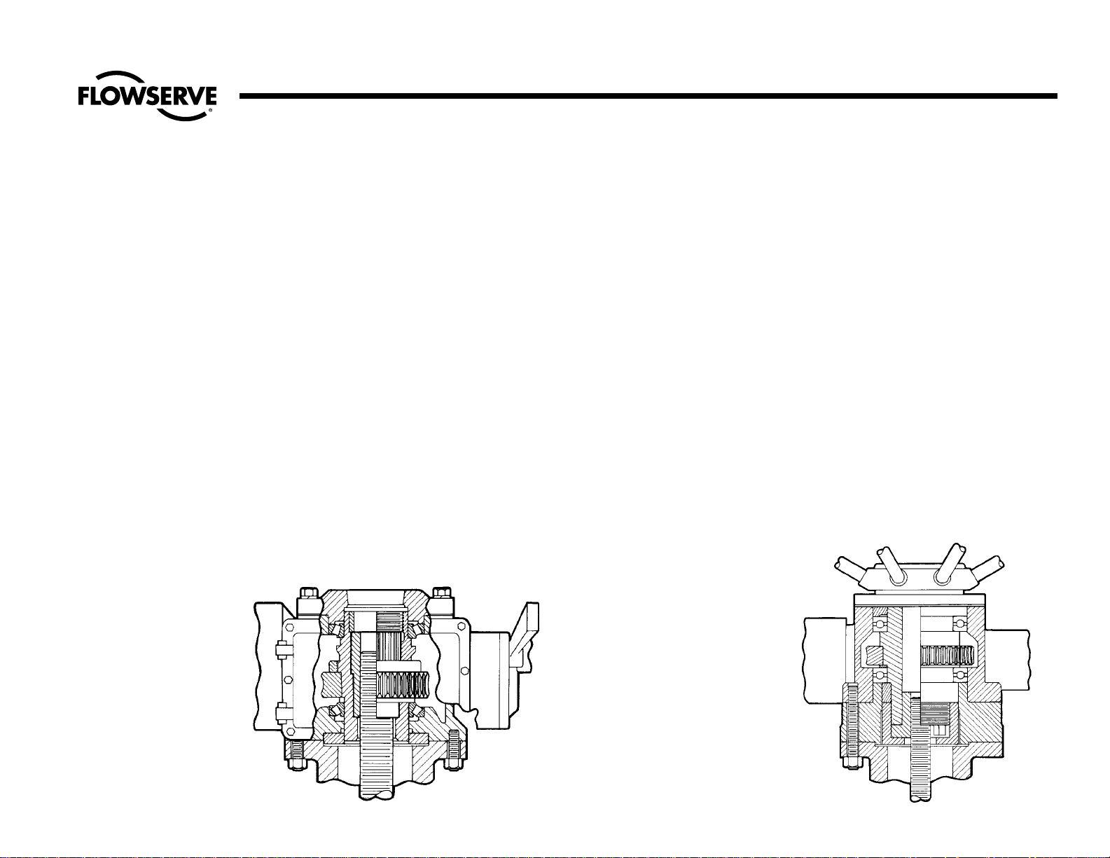
28
Flow Control Division
Edward Valves
Procedures For Removing Manual
And Electro-mechanical Actuators
From Valve Yokes
Equiwedge pressure seal gate valves are
often equipped with a variety of manual
and/or electro-mechanical actuators. A
number of these are illustrated in this section. Basically, there are two types of actuators:
(a) Those which take both torque and
thrust forces.
(b) Those which supply only the torque
to open or close the valve.
In type (a), the actuator is equipped with a
stem nut and thrust bearings that can withstand the thrust and torque loads imposed.
THIS TYPE SHOULD NOT BE REMOVED
WITH PRESSURE IN THE VALVE.
In type (b),the actuator is connected to the
valve yoke bushing by a key or spline, or
by other means, and delivers only the
torque load.
The most common is type (a) because of
the non-revolving, rising stem. This type is
used in both manual and electro-mechanical actuators.
TYPE (a) TORQUE AND THRUST
ACTUATOR DISASSEMBLY
Limitorque Actuator Illustration No. 18
Rotork Units Illustration No. 19
Torkmatic units (Manual)
Illustration No. 20, pg. 29
Auma units Illustration No. 21, pg. 29
Follow these guidelines:
1. Position the valve gate just off the
seat.
2. Disconnect the electrical wiring to the
actuator.
3. Make sure the packing gland nuts
are tight.
4. Position a chain hoist of suitable
capacity to support the actuator so
that the handwheel can be rotated.
The pull point must be directly in line
with the stem.
5. Remove all nuts or cap screws from
the under side of the yoke flange.
6. Turn the actuator handwheel to close
the valve. This will cause the actuator
to rise and unthread the stem nut
from the stem. As this takes place, the
weight of the actuator should be
taken by the hoist to prevent damage
to the stem threads.
7. When the stem threads are disengaged, lift the actuator clear of the
stem and place it down on a clean
area for further disassembly, if
required. If there is additional work
to do on the valve, refer to the proper valve type and proceed to disassemble the valve.
Appendix A
Limitorque Actuator Rotork Actuator
Illustration No. 18 Illustration No. 19
Page 29
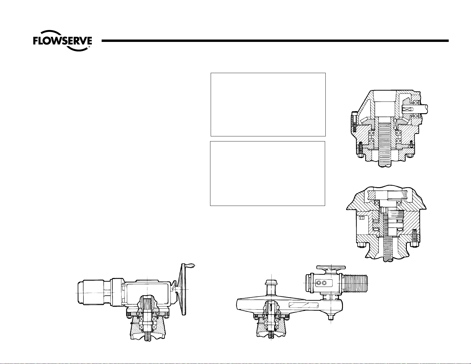
29
Flow Control Division
Edward Valves
Appendix A (cont.)
TYPE (b) TORQUE ONLY
DISASSEMBLY PROCEDURE
Limitorque Illustration No.22
AUMA Illustration No.23
1. Position the valve gate just off the
seat.
2. Disconnect the electrical wiring to the
actuator.
3. Position a chain hoist of adequate
capacity to the actuator. The pull
point must be directly in line with the
valve stem.
4. Remove all nuts or cap screws from
under the flange.
5. Using a hoist, raise the actuator
above the yoke bushing and position
away. If the actuator is keyed to the
yoke bushing, remove the key so it
will not be lost.
If there is further work to do on the
valve, refer to the proper valve type and
proceed with disassembly.
CAUTION:
UPON REASSEMBLY OF A VALVE EQUIPPED
WITH AN ELECTRO-MECHANICAL
ACTUATOR, THE OPEN AND CLOSED LIMIT
SWITCHES MUST BE RESET. PLEASE REFER
TO THE MAINTENANCE MANUAL PRO-
VIDED BY THE ACTUATOR MANUFACTURER
FOR APPROPRIATE INSTRUCTIONS.
WARNING
SHOULD IT BECOME NECESSARY
TO CHANGE THE TORQUE SWITCH
SETTING FOR ANY REASON, YOUR
LOCAL EDWARD VALVES REPRESENTATIVE
SHOULD BE CONTACTED IN ORDER
THAT A CORRECT NEW SET CAN BE
OBTAINED FROM THE FACTORY.
The torque switch of the motor actuated
valve is set during factory assembly to
close the valve against the specified differential pressure and requires the same special attention for resetting.
Illustration No. 20
Illustration No. 21
Illustration No. 23Illustration No. 22
Torkmatic Manual Actuator
Auma Actuator
Limitorque Actuator
Auma Actuator
Page 30
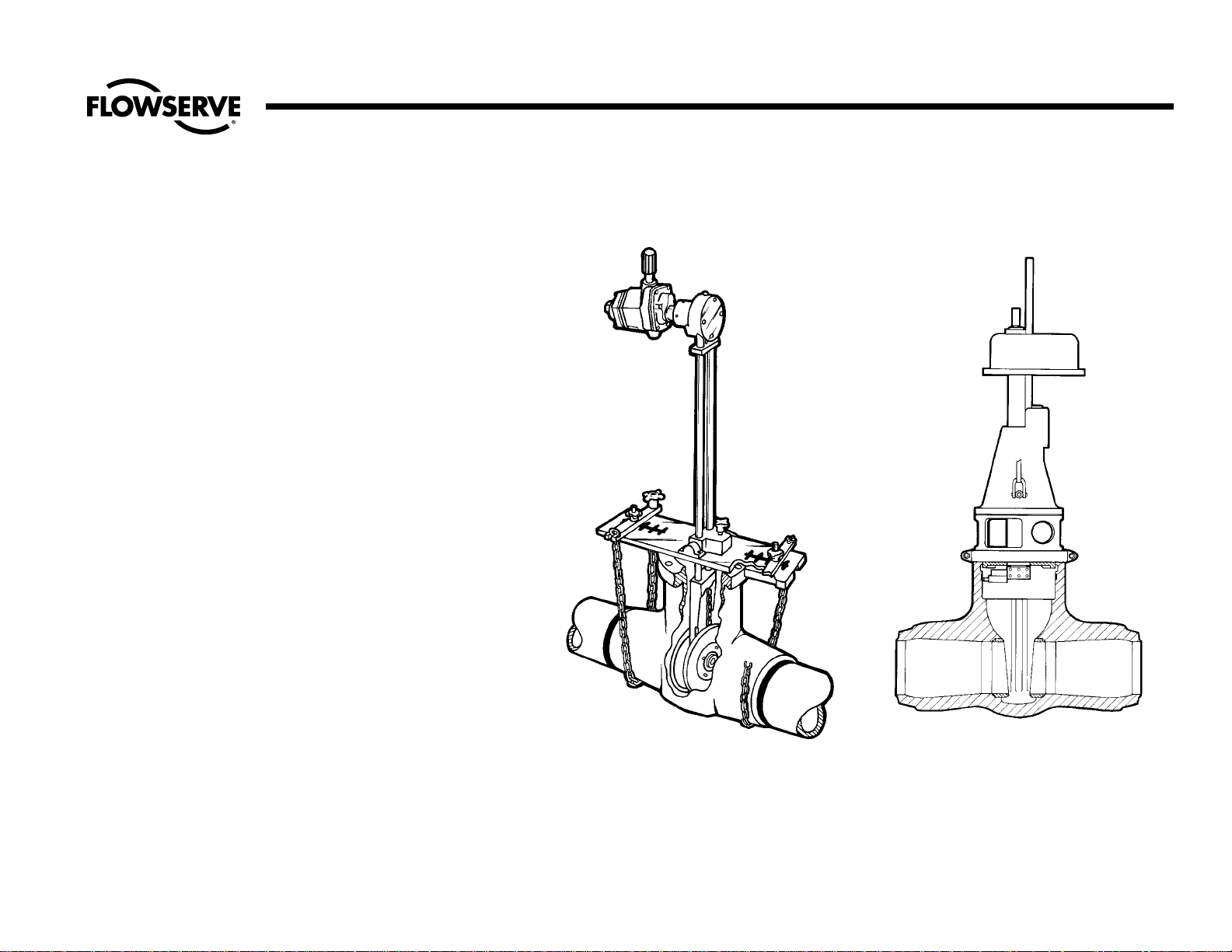
30
Flow Control Division
Edward Valves
Valve Tools Available For Rental
The following tools are available from the
Edward Valves Raleigh plant on a rental
basis:
Dexter Seat Refinishing Machines for
valves sizes 3 to 28. See illustration No.
24.
Portable boring machines that can be used
to machine the pressure seal area of the
body in case of damage or because of
weld repair. See illustration no. 25.
Contact your local Edward Valves
representative for details on cost and
availability.
A group of skilled service representatives is
also available to assist in repairs.
Appendix B
Typical Dexter Gate Valve Seat
Refinishing Machine
Portable Boring Machine
Attached To Gate Valve Body
Illustration No. 25Illustration No. 24
Page 31
Flow Control Division
Edward Valves
Flowserve Corporation has established industry leadership in the design and manufacture of its products. When properly selected, this Flowserve product is designed to perform its intended function safely during its useful life.
However, the purchaser or user of Flowserve products should be aware that Flowserve products might be used in numerous applications under a wide variety of industrial service conditions. Although Flowserve can (and often does)
provide general guidelines, it cannot provide specific data and warnings for all possible applications. The purchaser/user must therefore assume the ultimate responsibility for the proper sizing and selection, installation, operation,
and maintenance of Flowserve products. The purchaser/user should read and understand the Installation Operation Maintenance (IOM) instructions included with the product, and train its employees and contractors in the safe use of
Flowserve products in connection with the specific application.
While the information and specifications contained in this literature are believed to be accurate, they are supplied for informative purposes only and should not be considered certified or as a guarantee of satisfactory results by
reliance thereon. Nothing contained herein is to be construed as a warranty or guarantee, express or implied, regarding any matter with respect to this product. Because Flowserve is continually improving and upgrading its product
design, the specifications, dimensions and information contained herein are subject to change without notice. Should any question arise concerning these provisions, the purchaser/user should contact Flowserve Corporation at any
one of its worldwide operations or offices.
© 2003 Flowserve Corporation, Irving, Texas, USA. Flowserve and Edward Valves are registered trademarks of Flowserve Corporation. V-378 R1 3/03 Printed in USA
FLOWSERVE CORPORATION
FLOW CONTROL DIVISION
Edward Valves
1900 South Saunders Street
Raleigh, NC 27603 USA
Toll- Free Telephone Service
(U. S. and Canada)
Day: 1-800-225-6989
After Hours Customer Service
1-800-543-3927
US Sales Offices
Phone: 919-832-0525
Facsimile: 919-831-3369
Facsimile: 919-831-3376
Visit Our Website
www.edwardvalves.com
For more information about Flowserve Corporation, contact www.flowserve.com or call USA 1-800-225-6989.
 Loading...