

Page 1

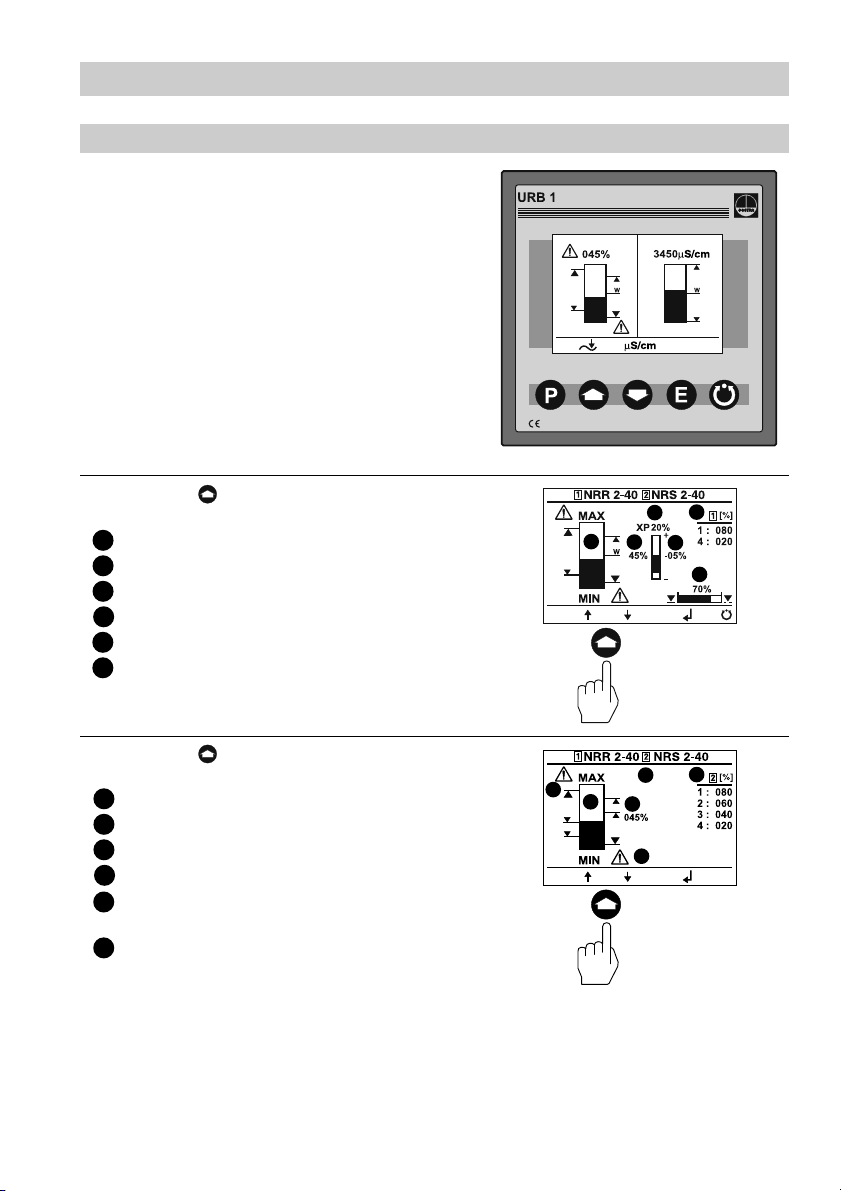
URB 1
Installation Instructions 810375-03
Operating Terminal and Display Unit URB 1
1
Page 2

Contents
Page
Important Notes
Usage for the intended purpose ......................................................................................8
Safety note ......................................................................................................................8
Explanatory Notes
Scope of supply ..............................................................................................................8
System description ......................................................................................................8, 9
Function .......................................................................................................................... 9
Technical data ............................................................................................................... 10
Installation
URB 1 ...........................................................................................................................10
Example of installation ................................................................................................ 79
Wiring
Wiring diagram ........................................................................................................ 4, 12
Basic Settings
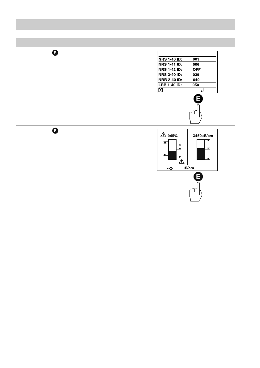
CAN bus ...................................................................................................................... 13
Node ID for GESTRA bus-based devices URB 1 ....................................................... 13
Factory set default values ............................................................................................ 13
Adjusting display brightness ................................................................................. 14, 15
Changing factory set node ID of URB 1 / adjusting & changing node ID of URB 1 . 16– 18
Possibilities to display bus devices ............................................................................. 18
Setting / changing node IDs of bus-based equipment.......................................... 19– 22
Visual display / parameterisation of bus-based equipment ................................. 23–28
0 %/100 % calibration for capacitance level monitoring system .......................... 29–31
Calibrating feedback potentiometer of an external control valve ......................... 32– 35
Establishing switchpoints and proportional coefficient X
Adjusting sensitivity of response ........................................................................... 40, 41
Setting relay delay times .......................................................................................42– 44
Adjusting conductivity controller ........................................................................... 45– 57
Adjusting LIN (linear) temperature compensation ................................................ 58– 60
Adjusting NORM (standard curve) temperature compensation ........................... 61–65
Enabling AUTO temperature compensation ............................................................ 66, 67
Disabling temperature compensation ................................................................... 68, 69
.................................... 36–39
P
2
Page 3

Contents
Page
Operation
Manual operation via external control valve ............................................................... 70
Stand-by operation with the steam boiler disconnected............................................. 71
System Malfunctions
Systematic malfunction analysis for troubleshooting .................................................. 72
Fault finding list ...................................................................................................... 73, 74
Annex
Establishing / changing node ID ................................................................................. 75
Factory set node IDs .............................................................................................. 75, 76
Table: standard curves ................................................................................................ 77
Declaration of conformity............................................................................................. 78
3
Page 4
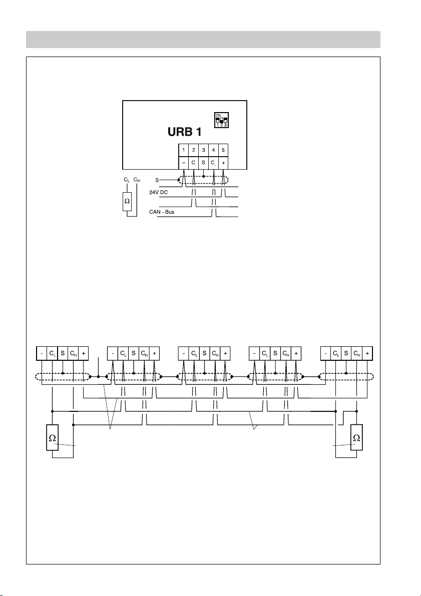
Wiring Diagram
Terminating resistor 120 Ω,
Fig.1
Paired cable
Operating
terminal
URB 1
Level switch
NRS
CEP*)
Voltage supply CAN data line
Terminating resistor
120 Ω
*) CEP = central earthable point
Fig. 2
4
Conductivity
controller
LRR 1-40
Conductivity
electrode
LRG 16-40
Terminating resistor
120 Ω
Electrode
NRG .. .
Page 5
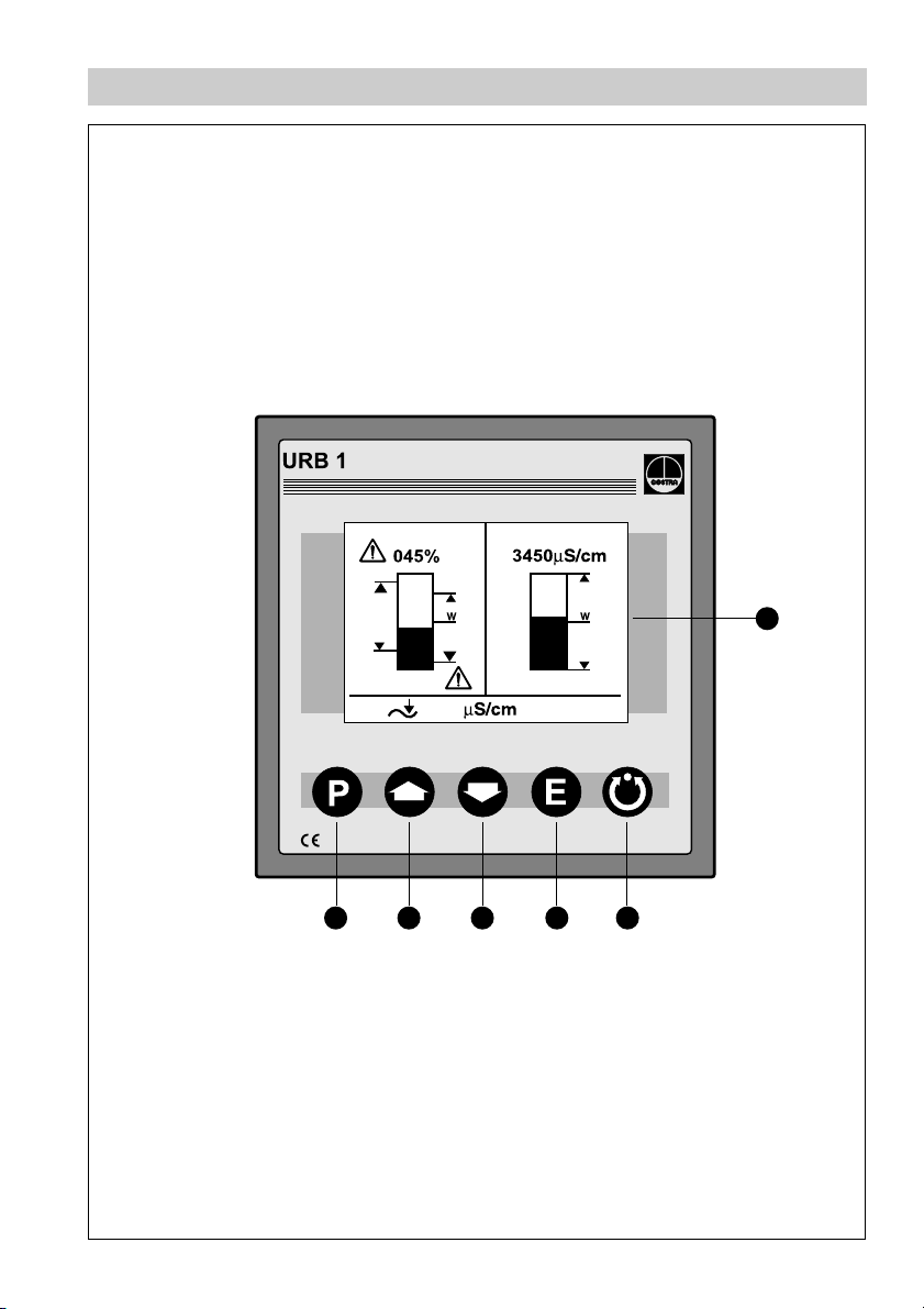
Functional Elements
6
Fig. 3
1 2 3 4
5
5
Page 6

Functional Elements
7
B
Fig. 4
6
A
A
Page 7

Key
Program button for switching between operating mode and parameterisation mode
1
Increase button
2
3
Decrease button
4
Enter button
5
Manual / automatic button
6
Illuminated LCD display, resolution 128 x 64 pixels
Code switch for baud rate setting
7
A
Fixing screws for panel mounting
Five-pole connector
B
7
Page 8

Important Notes
Usage for the intended purpose
Use operating terminal & display unit URB 1 only in conjunction with GESTRA
Spector bus systems (CANopen).
Safety Note
Use operating terminal and display unit URB 1 only for operating and viewing
GESTRA CAN bus systems.
The equipment must only be installed by qualified staff.
Qualified staff are those persons who – through adequate training in electrical
engineering, the use and application of safety equipment in accordance with
regulations concerning electrical safety systems, and first aid & accident prevention –
have achieved a recognised level of competence appropriate to the installation and
commissioning of this device.
Explanatory Notes
Scope of supply
URB 1
1 Operating terminal and display unit URB 1 (in plastic case)
2 Fixing screws for panel mounting
1 Installation manual
System description
The URB 1 is a user-friendly operating terminal and display unit for GESTRA CAN
bus systems using the CANopen protocol. The equipment makes retrieving and
processing standard functions of associated system components very easy.
In addition, the URB 1 simplifies the parameterisation procedure: The switchpoints,
proportional band and response sensitivity can be adjusted by means of the keypad
regardless of the actual level. The energizing and de-energizing times of the relays
can be set individually for their respective switchpoints.
The following tables specifiy the GESTRA systems that can be displayed by the
URB 1.
8
Page 9
Explanatory Notes – continued –
System description – continued –
Standard display information
Actual value (bar chart) ●● ●
Actual value (numerical value) ●● ●
Switchpoint (symbol) ●●● ●
High level alarm (electrode HW) ●●● ●
Low level alarm (electrode LW) ●●● ●
Manual/automatic operation ●● ●
Stand-by mode ●
Unit [µS/cm] or [ppm] ●
Low level limit ●
High level limit ●
Alarm (warning triangle) ●●
Further display information
Actual value (continuous) ●● ●
Switchpoints ●●● ●
Setpoint ●●
Deviation ●●
Valve position ●●
Intermittent blowdown ●
Intermittent blowdown interval ●
Purging pulse 24 h ●
Current CAN bus addresses ●●●●● ●
NRS 1-40 NRS 1-41 NRS 1-42
NRS 1-40 NRS 1-41 NRS 1-42
Level Conductivity
NRS 2-40 NRR 2-40
Level Conductivity
NRS 2-40 NRR 2-40
LRR 1-40
LRR 1-40
Function
The URB 1 communicates with other GESTRA system components via a designated
CAN bus using the CANopen protocol to DIN ISO 11898.
The URB 1 can also be used to operate and display further system components
during operation.
■ Capacitance level switch type NRS 2-40 CANopen
■ Level controller type NRR 2-40 CANopen
■ Conductivity level switch type NRS 1-42 CANopen
■ Low-level alarm to TRD 604/EN type NRS 1-40 CANopen
■
High-level alarm to TRD 604/EN type NRS 1-41 CANopen
■
Conductivity controller and limiter to TRD 604/EN type NRS 1-41 CANopen
9
Page 10

Explanatory Notes – continued –
Technical data
Type approval no.
TÜV · 98-399 (level)
TÜV · WÜL · 02-007 (conductivity)
Input
Power supply: 18 V – 36 V DC
Interface for CAN bus using CANopen protocol to DIN ISO 11898
Output
Interface for CAN bus using CANopen protocol to DIN ISO 11898
Indicators and adjustors
1 illuminated display, resolution: 128 x 64 pixels
5 push buttons
1 three-pole code switch for baud rate setting
Supply voltage
18 V – 36 V DC
Protection
Front panel: IP 54 to DIN EN 60529
Back: IP 00 to DIN EN 60529
Admissible ambient temperature
0°C – 55 °C
Case material
Front face: Aluminium with polyester membrane
Casing: Noryl GFN 2 SE 1, glass-fibre reinforced
Weight
Approx. 0.3 kg
Installation
URB 1
Panel mounting
1. Provide panel cut-out, dimensions: 92
2. Install URB 1 using the fixing clips supplied with the equipment.
Tool
■ Screwdriver (5.5/100)
10
+0.8
x 92
+0.8
.
Page 11
Wiring
Note that multi-core control cable with conductors linked in pairs, e. g. UNITRONIC
BUS CAN 2 x 2 x .. mm
2
or RE-2YCYV-fl 2 x 2 x .. mm2 .
®
The baud rate (data transfer rate) dictates the cable length between the bus nodes
and the total power consumption of the sensors dictates the conductor size.
8S9S01SetarduaBhtgnelelbaC
FFO NO FFO s/tiBk052 m521
sgnittesyrotcaF
NONOFFOs/tiBk521m0525,0x2x2
FFOFFONOs/tiBk001m53357,0x2x2
NOFFONOs/tiBk05m005
FFONONOs/tiBk02m0001
NONONOs/tiBk01m0001
sriapforebmuN
2
]
mm[ezisrotcudnocdna
43,0x2x2
notnedneped,tseuqerno
noitarugifnocsub
The baud rate is set via a code switch. Reduce baud rate if cable is longer than
specified in the table above. Make sure that all bus nodes feature the same settings.
To protect the switching contacts fuse circuit with 2.5 A (anti-surge fuse) or according
to TRD regulations (1.0 A for 72 hrs operation).
When a max. cable length of more than 125 m (up to 1000 m) is desired, make
sure to modify the baud rate accordingly. Refer to pages 75 and 76 for more
details.
Wiring diagram
For wiring diagram refer to page 4.
Attention
■ Wire equipment in series. Star-type wiring is not permitted.
■ Interlink screens of control cables such that electrical continuity is
ensured and connect them once to the central earthing point (CEP).
■ If more than one system component is connected to a CAN bus
network provide the first and last equipment with a terminating resistor
of 120 Ω, Fig. 2
■ The CAN bus line must not be interrupted while operating with one or
more system components.
Any interruption will open the control circuit!
If the switching controller has to be replaced be sure to remove first
the terminal strips , Fig. 4
B
Note: Make sure that all system components connected are
operating
UNITRONIC® is a registered trademark of LAPP Kabelwerke GmbH, Stuttgart.
before removing the CAN bus line from the terminal strip!
not
11
Page 12

Wiring – continued –
Note
■
Connect screen only to terminal 3, ensuring electrical continuity and
connect equipment once to the central earthing point (CEP).
■
The loop resistance must be under 10 Ω.
■
The rated voltage is stated on the name plate.
■
Despite correct wiring H.F. interference caused by the installation may
lead to system breakdowns and malfunction messages. If necessary
refer to the fault finding lists of the respective bus equipment.
Tools
■ Screwdriver for slotted screws, size 2.5, completely insulated according to
VDE 0680
12
Page 13

Basic Settings
CAN-Bus
All level and conductivity controllers and associated electrodes are interconnected by
means of a CAN bus using the CANopen protocol. Every item of equipment features
an electronic address (node ID). The four-core bus cable serves as power supply and
data highway for high-speed data exchange.
The CAN address (node ID) can be set between 60 and 123.
The URB 1 is configured at our works and ready for service with other GESTRA
system components without having to set the node ID.
If several systems of the same kind are to communicate in one CAN bus
network, be sure to assign one node ID for each individual system component
(e. g. controller). Refer to page 75 and 76 for more information.
Node ID for GESTRA bus-based device URB 1
Example: Conductivity monitoring and control
Example: Level monitoring and control
Factory set default values
The URB 1 features the following factory default settings:
■ Baud rate: 250 kb/s
■ Node ID: 060 (Do not change this node ID unless required; highest permissible
setting: 123)
13
Page 14

Basic Settings – continued –
Adjusting display brightness
The brightness of the LCD display can be
adjusted as necessary.
Press and hold the button for a few
seconds.
The URB 1 enters the address
parameterisation mode.
Press button several times to reduce
the brightness.
14
several times briefly
several times briefly
Page 15
Basic Settings – continued –
Adjusting display brightness – continued –
Press button several times to
increase the brightness.
Press button briefly to save settings
and return to the main window.
several times briefly
twice briefly
15
Page 16
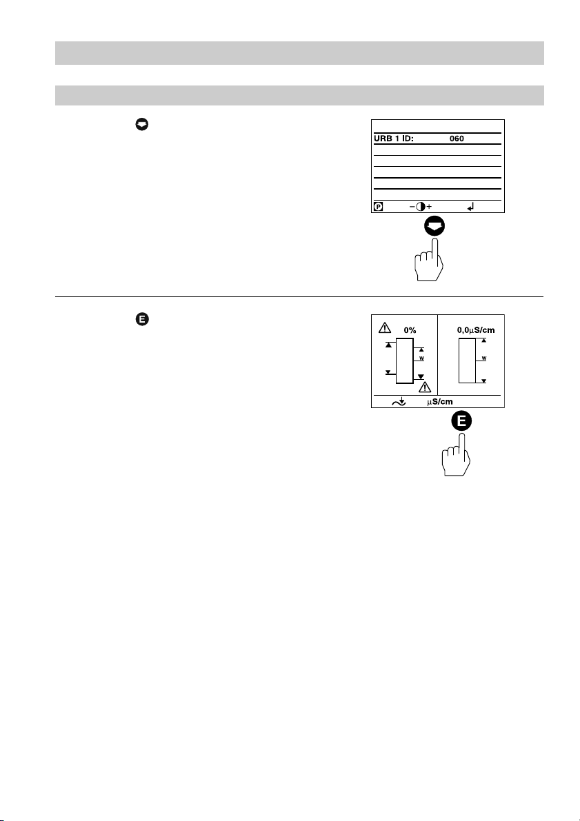
Basic Settings – continued –
Changing factory set node ID of the URB 1 / Adjusting & changing node ID
The factory set node ID of the URB 1 is
“060”. Node IDs below this value are
reserved for other GESTRA bus
components.
If additional operating terminals type URB 1
are used in a CAN bus system, you have to
set their node IDs to values above “060”.
Note that the newly established node IDs
must not be identical with node IDs of other
bus components.
Press and hold button for a few
seconds to enter the address
parameterisation mode.
Press button briefly to activate the
line selection mode.
16
a few seconds
briefly
Page 17

Basic Settings – continued –
Changing factory set node ID of the URB 1 / Adjusting & changing node ID – continued –
Press button briefly to activate the line
editing mode.
Use button or to increase or
decrease the first digit.
flashing
briefly
Press button briefly to move the
cursor two steps further.
flashing
twice briefly
Press button once briefly to select the
digit “1”.
flashing
once briefly
17
Page 18

Basic Settings – continued –
Changing factory set node ID of the URB 1 / Adjusting & changing node ID – continued –
Press button briefly to activate the line
selection mode.
In our example the node ID was set to
“061”.
briefly
Press button twice briefly to save
settings and return to the main window.
twice briefly
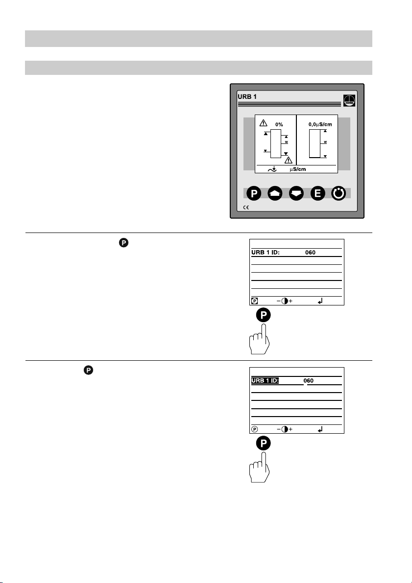
Possibilities to display bus devices
The URB 1 can display only one level monitoring device, one low-level alarm, one
high-level alarm and one conductivity monitoring device per vessel (e. g. steam
boiler or feedwater deaerator).
If the monitoring systems of more than one vessel are to be displayed, provide one
URB 1 per vessel.
18
Page 19

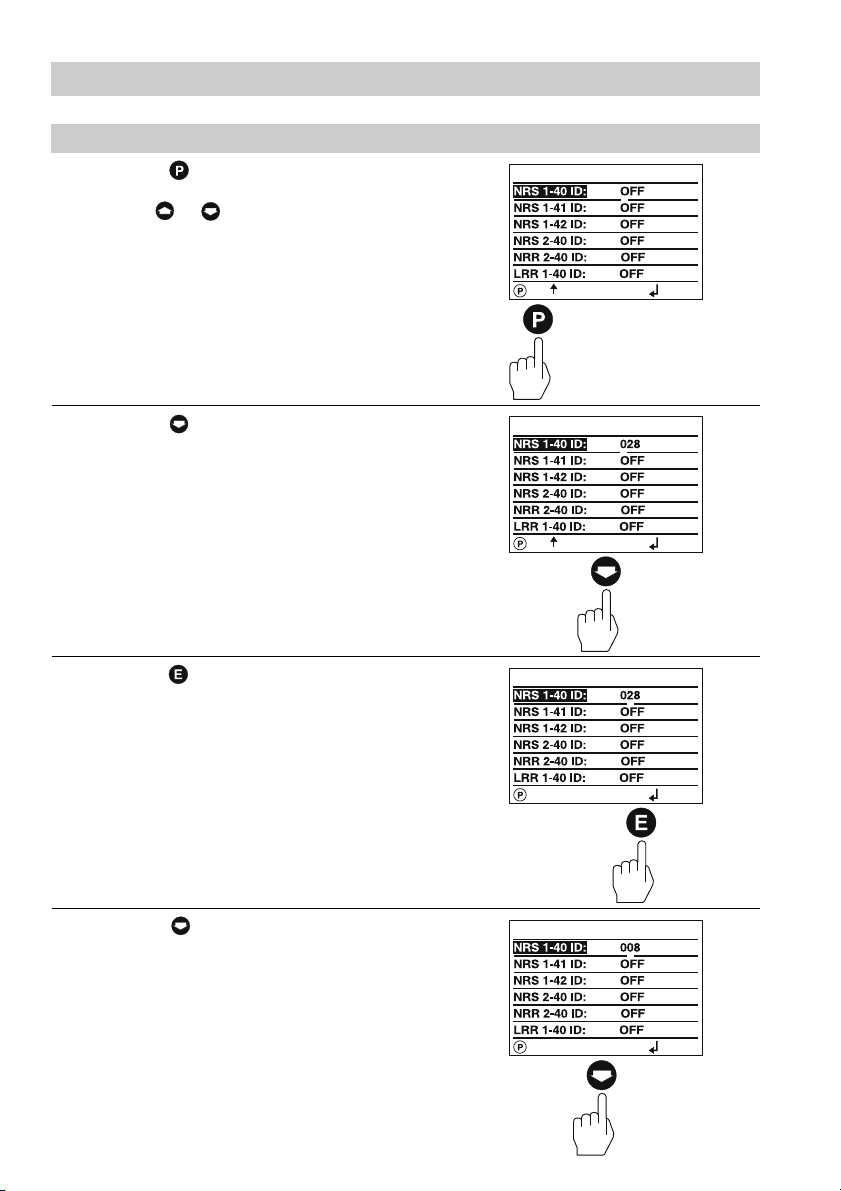
Basic Settings – continued –
Setting /changing node IDs of bus-based equipment
The standard default node ID setting of all
bus devices that can be displayed is “O
This setting acts as a wild card for all bus
devices which are not displayed with the
URB 1.
For each bus device that shall be displayed
by the URB 1 a node ID has to be
established manually.
We recommend to accept the factory set
node IDs of GESTRA bus devices. For the
relevant node ID setting please refer to the
corresponding installation manual of the
device.
Press button briefly to show the
address list and activate the
parameterisation mode.
FF”.
Press button briefly to activate the line
selection mode.
briefly
briefly
19
Page 20
Basic Settings – continued –
Setting /changing node IDs of bus-based equipment – continued –
Press button briefly to activate the line
editing mode.
Use button or to increase or
decrease the first digit.
flashing
briefly
Press button once briefly to select the
digit “0”.
flashing
once briefly
Press button briefly to move the
cursor one step further.
Press button twice briefly to select
the digit “0”.
20
flashing
briefly
flashing
twice briefly
Page 21
Basic Settings – continued –
Setting /changing node IDs of bus-based equipment – continued –
Press button briefly to move the
cursor one step further.
flashing
Press button seven times briefly to
select the digit “1”.
flashing
briefly
7 times briefly
Press button briefly to activate the line
selection mode.
Press button once briefly to move to
the next line.
The node ID of the NRS 1-41 can now
be adjusted.
briefly
once briefly
21
Page 22
Basic Settings – continued –
Setting /changing node IDs of bus-based equipment – continued –
Press button briefly to activate the
parameterisation mode.
In this example the node IDs of all bus
devices have already been adjusted.
If the display of the NRS 1-42 is required
set the node IDs of the NRS 2-40 and
NRR 2-40 to “O
Press button twice briefly to save the
settings and return to the main window.
FF”.
briefly
twice briefly
22
Page 23
Basic Settings – continued –
Visual display / Parameterisation of bus devices
The split-screen display window shows which
GESTRA bus devices can be indicated:
■ High-level limiter type NRS 1-41
■ Low-level limiter type NRS 1-40
■ Level switch type NRS 2-40
■ Level controller type NRR 2-40
■ Conductivity controller type LRR 1-40
Press button briefly to enter the display
window of the level controller NRR 2-40.
Actual level (graphical representation)
1
Actual level (percentage)
2
3
Setpoint deviation
4
Proportional band X
5
Switchpoints NRR 2-40
6
Valve position
p
Press button briefly to enter the display
window of the level switch NRS 2-40.
1
Actual level (graphical representation)
2
Actual level (percentage)
3
Control unit 2 highlighted
4
Switchpoints for control unit 2
5
Low-level signal
(flashes in the event of an LW alarm)
6
High-level signal
(flashes in the event of an HW alarm)
LW = low water (limiter NRS 1-40)
HW = high water (limiter NRS 1-41
5
4
1
2
3
6
briefly
4
6
3
1
2
5
briefly
23
Page 24

Basic Settings – continued –
Visual display / Parameterisation of bus devices – continued –
Press button briefly to enter the
parameterisation mode for the following
settings:
■ 0 % – 100 % calibration NRG 26-40
■ Switchpoints NRR 2-40
■ Proportional band NRR 2-40
■ Switchpoints NRS 2-40
Press button briefly to enter the
parameterisation mode for the following
settings:
■ Relay energizing delay times
■ Relay de-energizing delay times
briefly
briefly
Press button briefly to enter the error
messages window.
For more information see section
Malfunction, Troubleshooting, Fault
Finding List on pages 72 and 74.
Press button briefly to return to the
main window.
1
Actual conductivity value
2
Actual conductivity
(graphical representation)
24
briefly
1
2
briefly
Page 25

Basic Settings – continued –
Visual display / Parameterisation of bus devices – continued –
Press button briefly to enter the display
window of the conductivity controller LRR 1-40.
Actual conductivity value
1
2
Conductivity setpoint
3
M
AX conductivity value
24 h purging pulse for continuous
4
blowdown valve
5
Operating position of continuous
blowdown valve
Valve position of continous blowdown valve
6
Press button briefly to enter the
parameterisation mode for the following
settings:
■ µS/cm or ppm
■ Indication range of actual value
graphical representation
■ MAX conductivity value
■ Setpoint
■ MIN conductivity value
2
3
4
1
5
6
briefly
briefly
Press button briefly to enter the
parameterisation mode for the following
settings:
■ Proportional band X
■ Controller hysteresis
■ 24 h purging pulse for continuous
p
blowdown valve
■ Operating position of intermittent
blowdown valve
■ Relay contact 4: MIN limit /
Automatic intermittent boiler blowdown
Press button briefly to enter the
parameterisation mode for the following
settings:
■ Linear temperature compensation LIN
■ Automatic temperature compensation AUTO
■ Standard curve temperature compensation
NORM
■ Temperature compensation disabled OFF
briefly
briefly
25
Page 26

Basic Settings – continued –
Visual display / Parameterisation of bus devices – continued –
Press button briefly to enter the error
messages window.
For more information refer to section
Malfunction, Troubleshooting, Fault
Finding List on pages 72 and 74.
Press button briefly to return to the
main window.
briefly
briefly
26
Page 27

Basic Settings – continued –
Visual display / Parameterisation of bus devices – continued –
The split-screen display window shows which
GESTRA bus devices can be indicated:
Level switch type NRS 1-42
This window appears if, as in our example,
only the NRS 1-42 is displayed.
Press button briefly to enter the display
window of the level switch NRS 1-42.
H
IGH LEVEL switchpoint
1
2
Switchpoints
3
L
OW LEVEL switchpoint
1
2
2
3
Press button briefly to select either of the
following two settings:
■ Minimum conductivity of the fluid 0.5 µS/cm
■ Minimum conductivity of the fluid 10 µS/cm
briefly
briefly
27
Page 28

Basic Settings – continued –
Visual display / Parameterisation of bus devices – continued –
Press button briefly to enter the
parameterisation mode for the following
settings:
■ Relay energizing delay times
■ Relay de-energizing delay times
Press button briefly to enter the error
messages window.
For more information please refer to
section Malfunction, Troubleshooting,
Fault Finding List on pages 72 and 74.
briefly
briefly
Press button briefly to return to the
main window.
In this example only the bus device
NRS 1-42 is displayed.
If the node IDs of the bus devices
NRS 2-40 and NRR 2-40 have been
established such that the equipment can
be displayed on the URB 1, the
indication of these devices will take
priority over the NRS 1-42 and the
display window of the NRS 1-42 will be
blanked.
28
briefly
Page 29

Basic Settings – continued –
0 % /100 % calibration for capacitance level monitoring system
The split-screen main window shows
which GESTRA bus devices can be
displayed:
High level limiter NRS 1-41
Low level limiter NRS 1-40
Level switch NRS 2-40
Level controller NRR 2-40
Conductivity controller LRR 1-40
Before commissioning the installation
establish the measuring range of the
capacitance level electrode NRG 26-40 by
calibrating the 0 % and 100 % settings.
Press button three times briefly to enter
the window for calibrating the 0 % and
100 % settings.
Press button twice briefly to enter the
line editing mode.
Lower the water level in the vessel
to 0 %.
3 times briefly
flashing
twice briefly
29
Page 30

Basic Settings – continued –
0 % /100 % calibration for capacitance level monitoring system – continued –
Press button briefly to save the 0 %
level setting.
once briefly
Press button once briefly.
once briefly
Press button once briefly to activate the
line editing mode.
Raise the water level in the vessel to
100 %.
If, for practical reasons, it is not possible to
raise the water level to 100 % please
proceed as follows:
30
flashing
once briefly
Page 31

Basic Settings – continued –
0 % /100 % calibration for capacitance level monitoring system – continued –
Press button five times briefly.
Pressing the button in program mode
will decrement the calibration level in steps
of 10 to a minimum of 50 %.
In our example the calibration level is
50 %.
This calibration method saves time and
prevents the loss of feedwater.
Press button three times briefly to enter
the main window.
flashing
5 times briefly
3 times briefly
31
Page 32

Basic Settings – continued –
Calibrating the feedback potentiometer of an external control valve
The split-screen window shows which
GESTRA bus devices can be displayed:
■ High-level limiter NRS 1-41
■ Low-level limiter NRS 1-40
■ Level switch NRS 2-40
■ Level controller NRR 2-40
■ Conductivity controller LRR 1-40
Before commissioning the installation
calibrate the 0 % (
range of the feedback potentiometer of an
external control valve.
Press button briefly to enter the display
window of the level controller NRR 2-40.
CLOSED) and 100 % (OPEN)
Press button briefly to activate the
manual mode.
Pressing button or in this mode
allows the manual opening or closing of
an external control valve.
32
briefly
briefly
Page 33

Basic Settings – continued –
Calibrating the feedback potentiometer of an external control valve – continued –
Press button three times briefly to
activate the line editing mode for
calibrating the signal of the feedback
potentiometer.
flashing
3 times briefly
Press and hold down button until the
control valve is closed.
flashing
hold down
Press button once briefly to save the
current resistance value of the feedback
potentiometer as 0 % setting (valve
closed).
once briefly
33
Page 34

Basic Settings – continued –
Calibrating the feedback potentiometer of an external control valve – continued –
Press button briefly to select the
calibration of the 100 % setting.
briefly
Press button once briefly to activate the
line editing mode for calibrating the signal
of the feedback potentiometer.
flashing
once briefly
Press and hold down button until the
control valve is open.
34
flashing
hold down
Page 35

Basic Settings – continued –
Calibrating the feedback potentiometer of an external control valve – continued –
Press button three times briefly to save
the current resistance value of the
feedback potentiometer as 100 % setting
(valve
OPEN).
3 times briefly
Press button briefly to deactivate the
manual mode.
briefly
Press button once briefly to return to
the main window.
once briefly
35
Page 36

Basic Settings – continued –
Establishing switchpoints and proportional coefficient X
The split-screen main window shows
which GESTRA bus devices can be
indicated:
■ High-level limiter NRS 1-41
■ Low-level limiter NRS 1-40
■ Level switch NRS 2-40
■ Level controller NRR 2-40
■ Conductivity electrode LRR 1-40
Before commissioning the installation
establish proportional band and the M
M
IN switchpoints for the level controller
AX/
NRR 2-40.
For level switch NRS 2-40 you can
establish four switchpoints.
Press button three times briefly to enter
the window where you can establish the
switchpoints and the X
value.
p
p
3 times briefly
Press button once briefly to activate
the line editing mode.
Use button or to scroll back and
forth through the lines
36
once briefly
Page 37

Basic Settings – continued –
Establishing switchpoints and proportional coefficient Xp – continued –
Press button twice briefly to select the
switchpoint 1 (M
NRR 2-40.
Press button once briefly to activate the
line editing mode.
AX switchpoint) of the
twice briefly
flashing
once briefly
Press button once briefly to move to the
next digit in the same line.
flashing
once briefly
37
Page 38

Basic Settings – continued –
Establishing switchpoints and proportional coefficient Xp – continued –
Press button once briefly.
In our example switchpoint 1
(M
AX switchpoint) shall be established at
70 %.
flashing
once briefly
Press button once briefly.
The last digit in the line is selected and
remains “0” for our example switchpoint
M
AX 70 %.
flashing
once briefly
Press button once briefly to deactivate
the line editing mode.
Press button to go to the next line.
38
once briefly
Page 39

Basic Settings – continued –
Establishing switchpoints and proportional coefficient Xp – continued –
Press button once briefly.
Switchpoint 2 marks the upper limit of the
proportional band for the level controller
NRR 2-40.
The difference between switchpoint 2 and
switchpoint 3 gives the proportional band
X
. The example setting corresponds to
p
proportional band of 20 % (060 - 040).
Note that the proportional band must be
greater than “0”.
Press button once briefly.
Switchpoint 3 marks the lower limit of the
proportional band for the level controller
NRR 2-40.
The proportional coefficient and the M
switchpoint of the NRR 2-40 as well as
the switchpoints of the NRS 2-40 can be
adjusted as described above.
IN
once briefly
once briefly
Press button twice briefly to return to
the main window.
twice briefly
39
Page 40

Basic Settings – continued –
Adjusting sensitivity of response
The split-screen window shows which
GESTRA bus devices can be indicated:
■ High-level limiter NRS 1-41
■ Low-level limiter NRS 1-40
■ Level switch NRS 1-42
■ Conductivity controller LRR 1-40
Before commissioning the installation
adjust the response sensitivity of the NRS
1-42.
The response sensitivities of the highlevel and low-level limiters are factory
set and cannot be changed.
Press button twice briefly to select
either of the following two response
sensitivities:
■ 0.5 µS/cm
■ 10 µS/cm
Press button twice briefly to activate
the line editing mode.
Use buttons and to toggle between
the two settings.
40
twice briefly
flashing
twice briefly
Page 41

Basic Settings – continued –
Adjusting sensitivity of response – continued –
Press button briefly.
In our example the response sensitivity
0.5 µS/cm has been selected.
Press button three times briefly to save
the setting and return to the main window.
flashing
briefly
3 times briefly
41
Page 42

Basic Settings – continued –
Setting relay delay times
The split-screen window shows which
GESTRA bus devices can be indicated:
■ High-level limiter NRS 1-41
■ Low-level limiter NRS 1-40
■ Level switch NRS 2-40
■ Level controller NRR 2-40
■ Conductivity controller LRR 1-40
Before commissioning the installation set
the relay delay times for the individual
switchpoints.
Note that the relay delay times of the
low-level and high-level limiters are
factory set and
the URB 1.
Press button four times briefly to enter
the window for setting the relay delay times
of the switchpoints.
The symbol stands for relay energizing
delay.
The symbol stands for relay deenergizing delay.
A number, for instance “001” corresponds
to a delay time of 100
“030” corresponds to 3 sec and the max.
value “255” corresponds to 25.5 sec.
cannot be changed with
m
sec. The value
4 times briefly
Press button once briefly to activate
the line editing mode.
Use button or to scroll back and
forth through the lines.
42
once briefly
Page 43

Basic Settings – continued –
Setting relay delay times – continued –
Press button once briefly to activate the
line editing mode.
Press button once briefly.
Press button to move to the next digit in
the same line.
flashing
once briefly
flashing
once briefly
Press button once briefly.
In our example the digit “2” has been
selected.
flashing
once briefly
43
Page 44

Basic Settings – continued –
Setting relay delay times – continued –
Press button twice briefly to deactivate
the line editing mode.
In our example the relay delay time for the
M
AX switchpoint of the NRR 2-40 is 2 sec.
Press button once briefly.
Switchpoint 2 and switchpoint 3 of the
NRR 2-40 mark the upper and lower limit
of the proportional band. The relay
energizing and de-energizing delays
cannot be adjusted and feature the
number “000”.
The relay delay times of all other
switchpoints can be adjusted as described
above.
twice briefly
once briefly
Press button twice briefly to save the
settings and return to the main window.
44
twice briefly
Page 45

Basic Settings – continued –
Adjusting conductivity controller
The split-screen main window shows
which GESTRA bus devices can be
indicated:
■ High-level limiter NRS 1-41
■ Low-level limiter NRS 1-40
■ Level switch NRS 2-40
■ Level controller NRR 2-40
■ Conductivity controller LRR 1-40
Press button twice briefly to enter the
parameterisation mode for the following
settings:
■ µS/cm or ppm
■ Indicating range of actual value graphics
■ Max. conductivity
■ Setpoint
■ Min. conductivity
Press button twice briefly to activate
the line editing mode.
Use button or to scroll back and
forth through the lines.
twice briefly
flashing
twice briefly
45
Page 46

Basic Settings – continued –
Adjusting conductivity controller – continued –
Press button once briefly to select the
desired unit of measurement (here: ppm).
Press button once briefly to deactivate
the line editing mode.
All conductivity values metered will now be
indicated in [ppm].
flashing
once briefly
once briefly
Press button once briefly.
In this line you can calibrate the graphical
representation (bar chart) of the
conductivity value shown in the main
window. This setting will also calibrate the
actual value output (4 - 20 mA).
First ascertain the conductivity measuring
range used in your installation
(e. g. 0.5 µS/cm up to 20 µS/cm).
Press button once briefly to activate the line
editing mode.
You can choose between the following ranges:
■ 0.5 to 20 µS/cm ■ 0.5 to 1000 µS/cm
■ 0.5 to 100 µS/cm ■ 0.5 to 2000 µS/cm
■ 0.5 to 200 µS/cm ■ 0.5 to 6000 µS/cm
■ 0.5 to 500 µS/cm ■ 0.5 to 12000 µS/cm
46
once briefly
flashing
once briefly
Page 47

Basic Settings – continued –
Adjusting conductivity controller – continued –
Press button seven times briefly to
select the range 0.5 to 20 µS/cm.
Press button once briefly to deactivate
the line editing mode.
flashing
7 times briefly
once briefly
Press button once briefly to enter the
line where the conductivity setpoint of the
LRR 1-40 can be adjusted.
Press button once briefly to activate the line
editing mode.
once briefly
flashing
once briefly
47
Page 48

Basic Settings – continued –
Adjusting conductivity controller – continued –
Press button once briefly to move the
cursor one step further.
Press button twice briefly to select the
digit “3”.
flashing
once briefly
flashing
twice briefly
Press button five times briefly.
In our example a conductivity setpoint of
3000 µS/cm has been adjusted.
Press button once briefly to enter the line where
the M
IN conductivity limit of the LRR 1-40 can be
adjusted.
The M
IN switchpoint of the LRR 1-40 can be
adjusted in the same way as the conductivity
setpoint.
48
5 times briefly
once briefly
Page 49

Basic Settings – continued –
Adjusting conductivity controller – continued –
Press button once briefly to enter the
line where the M
LRR 1-40 can be adjusted.
The M
AX switchpoint of the LRR 1-40 can
be adjusted in the same way as the
conductivity setpoint.
Press button once briefly to deactivate
the line editing mode.
AX conductivity limit of the
once briefly
once briefly
Press button once briefly to enter the
parameterisation window for the following
settings:
■ Proportional band X
■ Control hysteresis
■ 24 h purging pulse for continuous
p
blowdown valve
■ Operating position of intermittent
blowdown valve
■ Relay contact 4 / automatic intermittent
boiler blowdown
Press button twice briefly to activate the line
editing mode.
In this line you can set the proportional band X
X
= 0: Two-position (on-off) control
p
X
> 0: Modulating control
p
once briefly
.
p
flashing
twice briefly
49
Page 50

Basic Settings – continued –
Adjusting conductivity controller – continued –
Press button once briefly to move the
cursor one step further.
Press button twice briefly to select the
digit “2”.
flashing
once briefly
flashing
twice briefly
Press button twice briefly.
In our example the proportional band X
p
was set to 20 %.
Press button once briefly to enter the line where
the control hysteresis of the LRR 1-40 can be
adjusted.
The hysteresis can be adjusted within a range of
0 % – 25 %.
The control hysteresis of the LRR 1-40 can be
adjusted the same way as the proportional
band X
If X
.
p
> 0 this function is deactivated.
p
50
twice briefly
once briefly
Page 51

Basic Settings – continued –
Adjusting conductivity controller – continued –
Press button once briefly to enter the
line where the 24 h purging pulse for the
continuous blowdown valve can be
adjusted.
Use buttons and to enable or,
respectively, disable the 24 h purging
pulse.
Press button once briefly to enter the
line where the operating position of the
continuous blowdown valve can be
changed.
once briefly
once briefly
Press button once briefly to enter the window
where the operating position and the feedback
potentiometer of the continuous blowdown valve
can be adjusted.
If X
> 0 the operating position setting
p
is deactivated.
The window shows also the reference values
(in %) as indicated by the scale of the GESTRA
continuous blowdown valve BAE (000 = 0 %, 035
= 35 %) and the current position of the continuous
blowdown valve (in %).
Press button twice briefly to activate the line
editing mode.
Use button or to change the values of the
digits. Press to go to the next digit.
The value 008 corresponds to an opening
position of 8 %. (Max. opening position 25 %)
once briefly
flashing
twice briefly
51
Page 52

Basic Settings – continued –
Adjusting conductivity controller – continued –
Press button once briefly.
The value 008 = 8
now selected.
Press button once briefly.
In this line you can establish the 0
value of the feedback potentiometer of the
continuous blowdown valve.
% operating position is
%
once briefly
once briefly
Press button once briefly to activate the
line editing mode.
Press and hold down button until the continuous
blowdown valve is closed.
52
flashing
once briefly
flashing
hold down
Page 53

Basic Settings – continued –
Adjusting conductivity controller – continued –
Press button once briefly.
The current resistance value of the
feedback potentiometer is saved as
0% position (valve CLOSED).
Press button once briefly to activate the
100% adjustment position.
once briefly
once briefly
Press button once briefly to activate the
line editing mode.
Press and hold down button until the
continuous blowdown valve is completely open.
flashing
blinkt
flashing
blinkt
flashing
once briefly
hold down
53
Page 54

Basic Settings – continued –
Adjusting conductivity controller – continued –
Press button once briefly.
The current resistance value of the
feedback potentiometer is now saved as
100% position (valve OPEN).
Press button three times briefly.
once briefly
3 times briefly
Press button once to activate the line
selection mode.
Press button four times briefly.
In this line you can decide whether you want
to use relay contact 4 (LRR 1-40) for MIN
alarm or for automatic intermittent boiler
blowdown.
The relay contact 4 of the LRR 1-40 is located
across terminals „28“, „29“ and „30“.
Please observe the wiring diagram of the
LRR 1-40.
54
once briefly
4 times briefly
Page 55

Basic Settings – continued –
Adjusting conductivity controller – continued –
Press button once briefly to activate the line
editing mode.
Press button once briefly to activate relay
contact 4 for establishing MIN alarm.
The relay contact 4 of the LRR 1-40 is
located across terminals „28“, „29“ und „30“.
Please observe the wiring diagram of the
LRR 1-40.
flashing
once briefly
flashing
once briefly
Press button once briefly to activate the
automatic intermittent blowdown function.
Press button once briefly to enter the
window where the following parameters
can be set:
■ Frequency of the intermittent blowdown
(in hours)
■ Duration of the intermittent blowdown
(in seconds)
flashing
once briefly
once briefly
55
Page 56

Basic Settings – continued –
Adjusting conductivity controller – continued –
Press button once briefly to activate the line
selection mode.
The frequency of the intermittent blowdown can
be adjusted in the line editing mode in the same
way as the proportional band X
.
p
once briefly
56
Page 57

Basic Settings – continued –
Adjusting conductivity controller – continued –
Press button once briefly.
The duration of the intermittent
blowdown can be adjusted in the line
editing mode in the same way as the
proportional band X
In our example the blowdown frequency
was set to 1 hour and the blowdown
duration to 1 second.
Press button twice briefly to accept the
configuration.
.
p
once briefly
twice briefly
Press button once briefly to return to
the main window.
once briefly
57
Page 58

Basic Settings – continued –
Adjusting LIN (linear) temperature compensation
The split-screen main window shows
which GESTRA bus devices can be
indicated:
■ High-level limiter NRS 1-41
■ Low-level limiter NRS 1-40
■ Level switch NRS 2-40
■ Level controller NRR 2-40
■ Conductivity controller LRR 1-40
Press button four times briefly to enter the
window where the following parameters can
be set:
■ Linear temperature compensation [% / °C]
■ Recording a temperature curve
■ Cell constant C of the conductivity
electrode
The factory set default setting is “TK:LIN”.
Press button once briefly to activate
the line editing mode.
58
4 times briefly
once briefly
Page 59

Basic Settings – continued –
Adjusting LIN (linear) temperature compensation – continued –
Press button once briefly to enter the line
where the linear temperature compensation
[% /°C] can be adjusted.
The factory set gradient 2.1 [%/ °C] is
normally used for steam boilers operating
with constant pressure.
When the boiler is at full working pressure
compare the indicated value with the reading
of a calibrated conductivity meter – the two
values must tally.
Press button once briefly to activate the
line editing mode.
If the reading of the calibrated conductivity
meter does not tally the value indicated by
the URB 1 the compensation gradient has
to be changed until the two values agree.
Example: With a gradient of 1.9 %/ °C the
two readings tally.
flashing
once briefly
once briefly
Press button once briefly to select the
digit “1”.
Press button once briefly to move
the cursor one step further.
flashing
once briefly
flashing
once briefly
59
Page 60

Basic Settings – continued –
Adjusting LIN (linear) temperature compensation – continued –
Press button twice briefly to select the
digit “9”.
flashing
Press button once briefly to accept the
configuration.
In our example a gradient of 1.9 %/ °C was
adjusted.
twice briefly
once briefly
Press button twice briefly to return to
the main window.
60
twice briefly
Page 61

Basic Settings – continued –
Adjusting NORM (standard curve) temperature compensation
The split-screen main window shows
which GESTRA bus devices can be
indicated:
■ High-level limiter NRS 1-41
■ Low-level limiter NRS 1-40
■ Level switch NRS 2-40
■ Level controller NRR 2-40
■ Conductivity controller LRR 1-40
Press button four times briefly.
The NORM (standard curve) temperature compen-
sation is suitable for steam boilers operating with
variable pressures, which means that the steam
boilers do not feature fixed working pressures/
temperatures (e. g. low load 10 bar, peak load 15 bar).
The standard curves of 11 feedwater conditioning
agents with different conductivities compensate the
thermal influences of the measurement within the
rated operating range. In our example we have started
from the factory set “TK:LIN” mode.
4 times briefly
Press button twice briefly to activate the
line editing mode.
flashing
twice briefly
61
Page 62

Basic Settings – continued –
Adjusting NORM (standard curve) temperature compensation – continued –
Press button twice briefly to select the
function NORM.
The function NORM allows the retrieval of
11 different standard curves stored in the
URB 1. The curves are applicable for different
feedwater conditioning agents with different
basic conductivities.
For more information see Annex (page 77).
Press button once briefly to activate the
line editing mode.
In this window the following parameters can
be set:
Standard curve temperature compensation
[% /°C]
Recording/adding a temperature curve
Cell constant of the conductivity electrode
Our example shows the factory setting “00”,
which means that no standard curve has
been selected and activated.
flashing
twice briefly
once briefly
Press button once briefly to enter the
line where you can select a standard curve.
For more information see Annex (page 77).
Press button once briefly to activate the
line editing mode.
62
once briefly
flashing
once briefly
Page 63

Basic Settings – continued –
Adjusting NORM (standard curve) temperature compensation – continued –
Press button once briefly to move the
cursor one step further.
flashing
Press button once briefly to select
the digit “1”.
flashing
once briefly
once briefly
Press button once briefly to accept the
configuration.
The standard curve “01” is now active.
The temperature values of the standard
curve “01” are based on the conditioning
agent caustic soda with a basic conductivity
of 260 µS/cm at 25°C.
For more information see Annex (page 77).
Press button once briefly to enter the line where
you can start recording the temperature/
conductivity curve that is characteristic of your
steam boiler.
The temp./conductivity values recorded by the
system cover the whole room temp. to service
temp. range.
In case of variable pressure operation we
recommend that you also record the AUTO curve.
If the standard curves are not suitable you can then
still use the AUTO curve.
once briefly
once briefly
63
Page 64

Basic Settings – continued –
Adjusting NORM (standard curve) temperature compensation – continued –
Press button once briefly to activate the
line editing mode.
flashing
once briefly
Press button once briefly to select the
function “start”.
flashing
once briefly
Press button once briefly to finish the
configuration.
Raise temp./ pressure until the steam boiler
settles at full working pressure (in case of
variable pressure operation until the highest
operating pressure is reached).
The LRR 1-40 will now record the
temperature/conductivity values and saves
them as AUTO curve in the URB 1.
The number of recorded temp./conductivity
values is indicated in the line “Temp.”.
Press button once briefly.
The recording of the AUTO curve is
finished once the steam boiler has
reached its working pressure.
In our example 15 temp./conductivity
values were recorded. A temperature of
181.7 °C was detected at the measuring
point of the conductivity electrode
LRG 16-40, which corresponds to a boiler
pressure of 10.3 bar.
64
once briefly
flashing
once briefly
Page 65

Basic Settings – continued –
Adjusting NORM (standard curve) temperature compensation – continued –
Press button twice briefly to select
the function “Stop”.
The recording of the temperature/
conductivity values is now finished.
The boiler specific AUTO curve can be
activated on the display “TK:AUTO”.
For more information see page 77.
Press button three times briefly to
return to the main window.
flashing
once briefly
3 times briefly
65
Page 66

Basic Settings – continued –
Enabling AUTO temperature compensation
The split-screen main window shows
which GESTRA bus devices can be
indicated:
■ High-level limiter NRS 1-41
■ Low-level limiter NRS 1-40
■ Level switch NRS 2-40
■ Level controller NRR 2-40
■ Conductivity controller LRR 1-40
Press button four times briefly.
The AUTO curve temperature compensation is
suitable for steam boilers operating with variable
pressures, which means that the steam boilers do
not feature fixed working pressures/temperatures
(e. g. low load 10 bar, peak load 15 bar).
The procedure for recording an AUTO curve is
described on pages 63 to 65.
In our example we have started from the setting
“TK:NORM”.
4 times briefly
Press button twice briefly to activate
the line editing mode.
66
flashing
twice briefly
Page 67

Basic Settings – continued –
Enabling AUTO temperature compensation – continued –
Press button once briefly to select the
function “Auto”.
flashing
Press button once briefly to finish the
configuration.
In our example we have activated an AUTO curve
with 15 temp./conductivity values which has been
recorded and stored in the URB 1.
A new AUTO curve can always be recorded which
will then overwrite the old one.
The procedure of recording an AUTO curve has
been described on pages 63 to 65.
once briefly
once briefly
Press button once briefly to return to
the main window.
once briefly
67
Page 68

Basic Settings – continued –
Disabling temperature compensation
The split-screen main window shows
which GESTRA bus devices can be
indicated:
■ High-level limiter NRS 1-41
■ Low-level limiter NRS 1-40
■ Level switch NRS 2-40
■ Level controller NRR 2-40
■ Conductivity controller LRR 1-40
Press button four times briefly.
Some industrial applications may require
disabling the temperature compensation. Note
that with this mode all conductivity values
displayed by the URB 1 are absolute
readings of the current conductivity.
In our example we start from the factory set
“TK:LIN” mode.
Press button twice briefly to activate
the line editing mode.
68
4 times briefly
flashing
twice briefly
Page 69

Basic Settings – continued –
Disabling temperature compensation – continued –
Press button three times briefly to
select the function “OFF”.
Press button once briefly to save settings and
finish the configuration.
The temperature compensation is now disabled.
flashing
3 times briefly
once briefly
Press button once briefly to return to
the main window.
once briefly
69
Page 70

Operation
Manual operation via external control valve
The split-screen main window shows which
GESTRA bus devices can be indicated:
■ High-level limiter NRS 1-41
■ Low-level limiter NRS 1-40
■ Level switch NRS 2-40
■ Level controller NRR 2-40
■ Conductivity controller LRR 1-40
Press button briefly to enter the display
window of the level controller NRR 2-40.
Press button briefly to activate the
manual mode.
Use buttons and in this mode to
manually open and close an external
control valve.
Press button a second time to disable
the manual mode and to move the control
valve back into the position dictated by the
controller NRR 2-40.
70
briefly
briefly
Page 71

Operation – continued –
Stand-by operation with the steam boiler disconnected
The split-screen main window shows which
GESTRA bus devices can be indicated:
■ High-level limiter NRS 1-41
■ Low-level limiter NRS 1-40
■ Level switch NRS 2-40
■ Level controller NRR 2-40
■ Conductivity controller LRR 1-40
Use an external switch to enable the stand-by
mode of the conductivity control.
After switching off the burner of the steam boiler
you can deactivate the control of the continuous
and intermittent blowdown valves in order to avoid
loss of boiler water (stand-by operation).
After returning to normal operation the continuous
blowdown valve moves into the control position
and an intermittent blowdown pulse is given
(if activated).
Please take the wiring diagram of the
installation manual for the LRR 1-40 into
consideration.
71
Page 72

System Malfunctions
Troubleshooting
The sources of malfunctions occurring in CAN bus systems operating with several busbased stations must be analysed systematically since faulty components or incorrect
settings can give rise to negative interactions with intact bus devices in the CAN bus
system. These unwanted interactions can cause error messages in fully functional bus
devices, which will make fault detection even more difficult.
We recommend the following systematic fault location procedure:
Step 1 (Start)
Detach terminal strips
in all sensing units of
bus devices.
Level electrode
Conductivity
electrode
Pressure sensor
Temperature sensor
Check
Use fault-finding list
to correct fault(s).
Final test: have all
faults been
eliminated?
System
Malfunction
Use fault-finding list
to identify the fault(s).
Cut off power supply
to the equipment.
72
Step 2
Plug in terminal strip
of the sensing unit of
one system, e. g.
NRS ...
and
NRG ... (sensor).
Step 3
Apply mains voltage
to bus devices of the
system e. g.
NRS ...
and
NRG ...
System O.K.
Detach terminal strips
between bus devices
of the sytem e. g.
NRS ...
and
NRG ...
Page 73

System Malfunctions – continued –
Fault Finding List
The data communication in the CAN
bus line is disrupted.
Check that the CAN bus line has been
wired according to the wiring diagram.
Check that the CAN bus line is not
interrupted due to conductor breakage.
Check that the controllers and
electrodes feature the correct node IDs.
The thermal fuse of one of the level
electrodes has been triggered.
Check that the level electrode has been
mounted as specified in the installation
manual.
Check whether external influences
have caused built-up of heat in the
electrode casing.
flashing flashing
5 times briefly
The thermal fuse of the conductivity
electrode has been triggered.
Check that the conductivity electrode
has been mounted as specified in the
installation manual.
Check whether external influences
have caused built-up of heat in the
electrode casing.
The conductivity electrode is
defective.
The temperature sensor of the
conductivity electrode is short circuited
or interrupted.
Replace conductivity electrode
LRG 16-40.
5 times briefly
5 times briefly
73
Page 74

System Malfunctions – continued –
Fault Finding List – continued –
The conductivity electrode is
defective.
The internal connecting cables of the
conductivity electrode are short
circuited or interrupted.
Replace conductivity electrode
LRG 16-40.
The CAN bus communication of a
controller is disrupted.
Check that the controller and the level
or conductivity electrode have been
mounted as specified in the wiring
diagram.
In our example there is a disruption in
the CAN bus communication of the lowwater level electrode 2 type NRG 16-40.
5 times briefly
once briefly
The CAN bus communication of a
controller is disrupted.
Check that the controller and the level
or conductivity electrode have been
mounted as specified in the wiring
diagram.
In our example there is a disruption in
the CAN bus communication of the
switching controller type NRS 1-40.
If faults occur that are not listed
above, please contact our subsidiary
or agency in your country.
74
once briefly
Page 75

Annex
Establishing / changing node ID
If several systems of the same kind are to communicate in one CAN bus network
establish one node ID for each individual system (e. g. controller).
Factory set node IDs
Controller
The individual node IDs must be adjusted manually on the respective devices.
Please observe the relevant installation instructions.
Attention
■ Do not assign the same node ID twice within the CAN bus network.
Electrode
75
Page 76

Annex – continued –
Fig. 5 Rear panel of the URB 1
76
S8
OFF
ON
OFF
ON
OFF
ON
Fig. 6 Default factory setting 250 kBit/s
S9 S0
OFF
ON
ON
OFF
OFF
OFF
ON
ON
ON
ON
ON
ON
Baud rate
250 kBit/s
125 kBit/s
100 kBit/s
50 kBit/s
20 kBit/s
10 kBit/s
Cable length
125 m
250 m
335 m
500 m
1000 m
1000 m
Page 77

Annex – continued –
Table: Standard Curves
.oNtnegagninoitidnoCC°52ta]mc/Sm[ytivitcudnoccisaB
1adoscitsuaC062
2adoscitsuaC0801
3adoscitsuaC0045
4adoscitsuaC00011
5etahpsohpmuidosirT091
6etahpsohpmuidosirT0011
7etahpsohpmuidosirT0095
8etahpsohpmuidosirT00211
9etiflusmuidoS089
01444euqilopiD002
11nixoveL591
77
Page 78

Annex – continued –
Declaration of conformity
We hereby declare that the equipment URB 1 conforms to the following European
guidelines:
■ LV directive 73/23/eec version 93/68/eec
■ EMC guideline 89/336/eec version 93/68/eec
which are based on the following harmonised standards:
■ LV standard EN 50178
■ EMC standard EN 50081-2, EN 50082-2
This declaration is no longer valid if modifications are made to the equipment without
consultation with us.
Bremen, 23rd May 2002
GESTRA GmbH
Dipl.-Ing. Stefan Bode
(Academically qualified engineer)
Head of R & D Dept. Electronics
Key
Fixing screw for panel mounting
A
Dipl.-Ing. Lars Bohl
(Academically qualified engineer)
Quality Assurance Manager
78
Page 79

Example of Installation
95
A
63
Fig. 7
95
79
Page 80

GESTRA Gesellschaften · GESTRA Companies · Sociétés GESTRA · Sociedades Gestra · Società GESTRA
Vertretungen weltweit · Agencies all over the world · Représentations dans le monde entier · Representaciones en todo el mundo · Agenzie in tutto il mondo
Great Britain
Flowserve Flow Control (UK) Ltd.
Burrel Road, Haywards Heath
West Sussex RH 16 1TL
Tel. 00 44 14 44 / 31 44 00
Fax 00 44 14 44 / 31 45 57
E-mail: sales@flowserve.com
France
Flowserve Flow Control S. A.S.
10 Avenue du Centaure, BP 8263
F-95801 CERGY PONTOISE CEDEX
Tél. 00.33.1 / 34 4326 60
Fax 00.33.1 / 34 43 26 87
E-mail: contact@gestra.fr
España
GESTRA ESPAÑOLA S.A.
Luis Cabrera, 86-88
E-28002 Madrid
Tel. 00 34 91/ 5 152 032
Fax 003491/4136747; 5152036
E-mail: gestra@gestra.es
Italia
Flowserve S.p. A
Divisione Italgestra
Via Prealpi, 30 – 20032 Cormano (MI)
Tel. 00 39 02 /66 3251
Fax 0039 02 / 66 32 55 60
E-mail: info@italgestra.it
Portugal
Flowserve Portuguesa, Lda.
Av. Dr. Antunes Guimarães, 1159
Porto 4100-082
Tel. 0035122/6198770
Fax 00351 22 / 61075 75
E-mail: gestra@gestra.pt
®
GESTRA GmbH
Postfach 10 54 60, D-28054 Bremen, Münchener Str. 77, D-28215 Bremen
Telefon +49 (0) 421 35 03- 0, Telefax +49 (0) 421 35 03- 393
E-Mail gestra.gmbh@flowserve.com, Internet www.gestra.de
A Unit of Flowserve Corporation
810375-03/304 · © 2002 GESTRA GmbH · Bremen · Printed in Germany
80
 Loading...