

Page 1

GESTRA
GESTRA Steam Systems
UNA 23
UNA 25
UNA 26
UNA 27
Installation Instructions 810516-06
Steam Traps
UNA 23, UNA 25, UNA 26, UNA 26h Stainless Steel, UNA 27h
1
Page 2

Contents
Page
Important Notes
Usage for the intended purpose .............................................................................................................. 4
Safety note ............................................................................................................................................. 4
Danger ................................................................................................................................................... 4
Attention ................................................................................................................................................ 4
PED (Pressure Equipment Directive) ....................................................................................................... 4
ATEX (Atmosphère Explosible) ................................................................................................................ 4
Explanatory Notes
Scope of supply...................................................................................................................................... 5
Description............................................................................................................................................. 5
Function ................................................................................................................................................. 5
Designs .................................................................................................................................................. 5
Technical Specification
UNA 23h/v, UNA 25h/v, UNA 26h/v, UNA 27h .......................................................................................... 6
Pressure / temperature ratings ............................................................................................................... 6
Corrosion resistance .............................................................................................................................. 6
Sizing ..................................................................................................................................................... 6
Name plate /marking ............................................................................................................................. 7
Design
Components ................................................................................................................................... 8 – 10
Key to components .............................................................................................................................. 11
Installation
UNA 23h/v, UNA 25h/v, UNA 26h/v, UNA 27h ........................................................................................12
Design with flanges .............................................................................................................................. 12
Design with screwed sockets ............................................................................................................... 12
Design with socket-weld ends ............................................................................................................. 12
Design with butt-weld ends .................................................................................................................. 12
Attention .............................................................................................................................................. 13
Heat treatment of welds ....................................................................................................................... 13
Hand vent valve.................................................................................................................................... 13
Tools .................................................................................................................................................... 13
Hand vent valve (optional extra)............................................................................................................ 13
Commissioning
UNA 23h/v, UNA 25h/v, UNA 26h/v, UNA 27h ........................................................................................13
2
Page 3

Contents – continued –
Page
Operation
Hand vent valve.................................................................................................................................... 14
Float lifting lever .................................................................................................................................. 14
Maintenance
Check steam trap ................................................................................................................................. 14
Clean / exchange control unit................................................................................................................ 14
Tools .................................................................................................................................................... 15
Clean / exchange sightglass cover ........................................................................................................ 15
Attention .............................................................................................................................................. 15
Torques................................................................................................................................................ 16
Spare Parts
Spare parts list ............................................................................................................................. 17 – 21
Annex
Declaration of conformity ..................................................................................................................... 22
3
Page 4

Important Notes
Usage for the intended purpose
UNA 23, UNA 25:
Use the steam traps only for the discharge of condensed steam within the admissible pressure/
temperature ratings.
Contact the factory for specific recommendations concerning the chemical resistance and suitability of
the valve material for the application in question.
UNA 26, UNA 26h Stainless Steel, UNA 27h:
Use the steam traps only for the discharge of condensates, liquids and condensable gases in pipes.
Use the equipment only within the specified pressure and temperature ratings and check corrosion
resistance and chemical suitability for the application in question.
Safety note
The equipment must only be installed and commissioned by qualified staff.
Maintenance and service work must only be performed by adequately trained persons who have a
recognised level of competence.
Danger
The steam trap is under pressure during operation.
When loosening flanged connections or sealing plugs, hot water, steam, corrosive liquids
or toxic gases may escape. This presents the danger of severe burns and scalds to the
whole body or severe cases of poisoning.
Installation and maintenance work should only be carried out when the system is
depressurized. Isolate the trap from both upstream and downstream pressure.
The steam trap becomes hot during operation. This presents the risk of severe burns to
hands and arms. Installation and maintenance work should only be carried out at room
temperatures.
Sharp edges on internals present a danger of cuts to hands. Always wear industrial
gloves for installation and maintenance work.
Attention
The name plate indicates the technical specification of the equipment.
Do not commission or operate a steam trap without name plate.
PED (Pressure Equipment Directive)
The equipment fulfills the requirements of the Pressure Equipment Directive PED 97/23/EC. UNA 23
and UNA 25 for applications with fluids of group 2; UNA 26, UNA 26h stainless steel and UNA 27h for
applications with fluids of group 1 and 2.
With CE marking (apart from equipment according to section 3.3).
ATEX (Atmosphère Explosible)
The equipment does not have its own potential source of ignition and is therefore not subject to the
ATEX Directive 94/9/EC. The equipment can be used in potentially explosive areas 0, 1, 2, 20, 21, 22
(1999/92/EC). The equipment is not Ex marked.
4
Page 5

Explanatory Notes
Scope of supply
UNA 23h/v, UNA 25h/v, UNA26h/v,
UNA 26h stainless steel, UNA 27h
1 Steam trap UNA 2..
1 Installation manual
Description
UNA 2.. are ball float traps with rolling ball closing mechanisms.
The steam traps work independently of back pressure, thus ensuring universal application.
The steam trap UNA features a body with bolted cover and a control unit. Two different control units are
available: Level-dependent SIMPLEX control for cold condensate and superheated steam, and
temperature-dependent DUPLEX control with automatic deaeration for saturated steam systems.
Optional item: sightglass cover with integral water-level gauge glass (UNA 23, PN 16).
Function
The ball valve of the control unit is operated by the float as a function of the condensate level in the
trap. The cross-sectional area (CSA) of the orifice dictates the max. flowrate when the valve is
completely open. The max. admissible differential pressure of the control unit is a function of the CSA
of the orifice and the density of the fluid to be discharged. There are different closing units (orifices)
available which can also be exchanged subsequently. Float traps equipped with control units DUPLEX
enable automatic temperature-dependent deaeration of saturated steam systems during start-up and
in continuous operation.
UNA 2. . with Simplex control
1 Steam trap UNA 2..
1 Hand vent valve with gasket
1 Installation manual
UNA 2 .. with float lifting lever
1 Steam trap UNA 2..
Float lifting lever installed
1 Lever extension
1 Installation manual
Design
UNA 23h, UNA 25h, UNA 26h, UNA 26h stainless steel:
for installation in horizontal pipes
UNA 23v, UNA 25v, UNA 26v:
for installation in vertical pipes
UNA 23h, UNA 23v:
with sightglass cover (integrated reflexion water level indicator)
5
Page 6
Technical Data
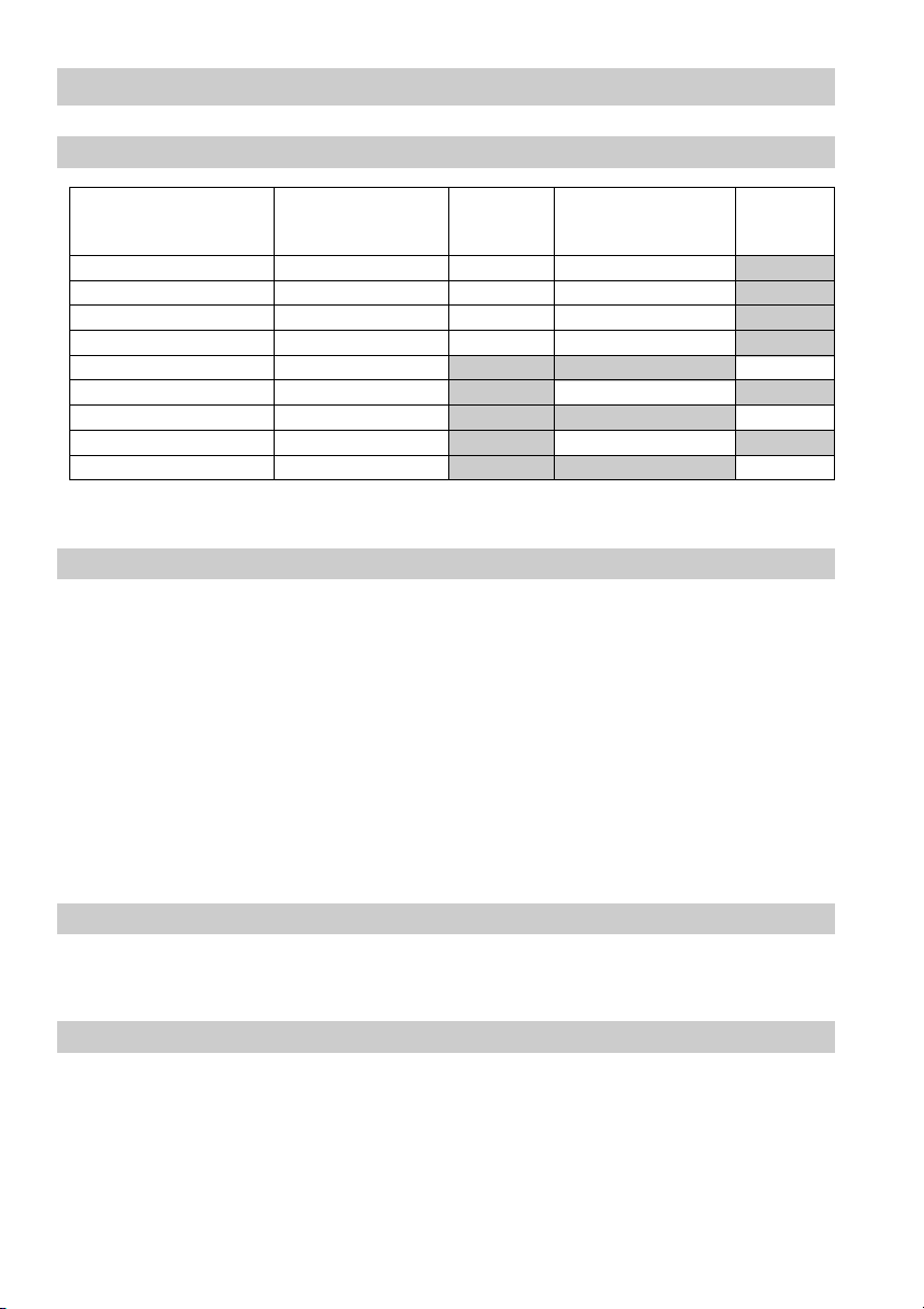
UNA 23h/v, UNA 25h/v, UNA 26h/v, UNA 27h
Orifices (O)
(Seat design)
O 2 2 ●●
O 4 4 ●●
O 8 8 ●●
O 13 13 ●●
O 16 16 ●
O 22 22 ●
O 28 28 ●
O 32 32 ●
1
) Observe pressure/temp. specifications.
2
) Inlet pressure minus outlet pressure.
O 45 45 ●
Max. admissible dif-
ferential pressure1)2)
∆∆
∆PMX [bar]
∆∆
UNA 23h/v
UNA 25h/v
UNA 26h/v
UNA 26h stainless steel
UNA 27h
Pressure / Temperature Ratings
UNA 2... without sightglass cover:
For pressure / temperature ratings see indications on trap body or name plate: pressure class
PN / Class, material number, max. temperature, max. pressure, max. differential pressure.
UNA 23h/v: max. admissible temperature: 300 °C
UNA 25h/v: max. admissible temperature: 350 °C
UNA 26h stainless steel: max. admissible temperature: 300 °C
UNA 26h/v: max. admissible temperature: 400 °C
UNA 23h/v with sightglass cover: max. admissible temperature: 240 °C
Reduced temperature limits for sightglass cover with integrated reflexion water level indicator.
If the pH value is above 9.0 and the fluid temperature exceeds 200 °C the glass will get more wear.
Corrosion Resistance
When used for its intended purpose the safe functioning of the steam trap will not be impaired by
corrosion.
Sizing
The trap body must not be subjected to sharp increases in pressure.
The dimensional allowances for corrosion reflect the latest state of technology.
6
Page 7
Technical Data – continued –
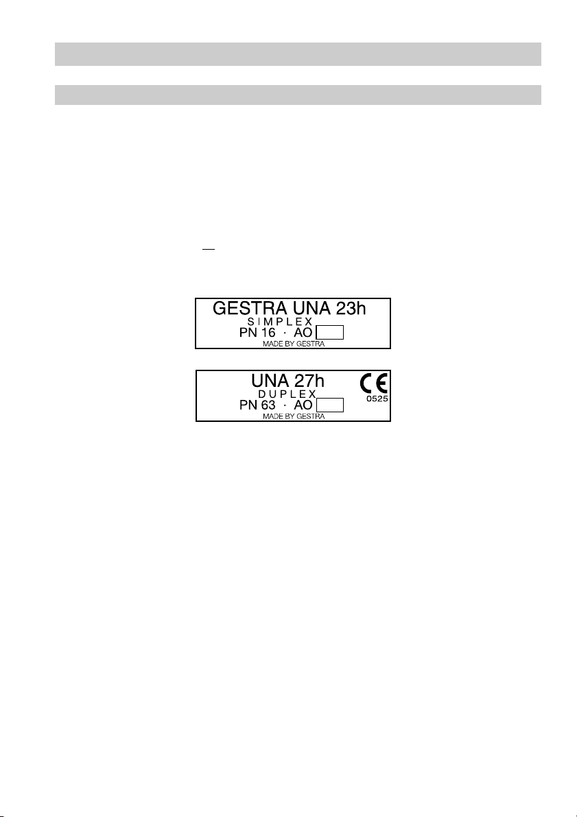
Name Plate / Marking
For pressure and temperature ratings see indications on trap body or name plate.
According to EN 19 the name plate must specify:
■ Manufacturer
■ Type designation
■ Pressure class PN or Class
■ Material number
■ Max. temperature
■ Stamp on name plate, e.g. specifies the manufacturing year and the quarter,
in this case the 4
th
quarter in 2004.
Fig. 1
4
04
7
Page 8
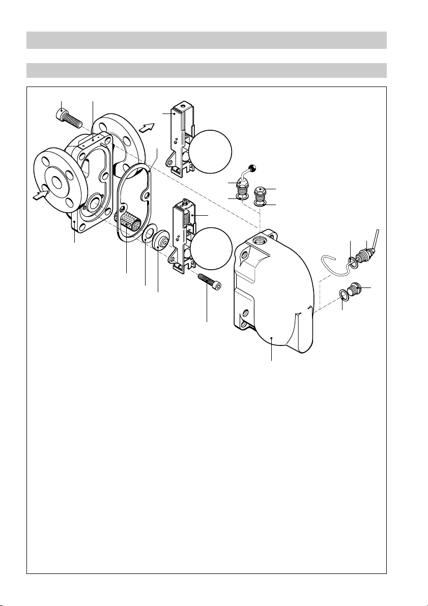
Design
Component Parts UNA 23h, UNA 25h, UNA 26h
AB
C
D
Fig. 2
O
N
M
L
K
G
E
F
J
H
F
F
F
I
H
8
Page 9

Design – continued –
Component Parts UNA 23v, UNA 25v, UNA 26v, UNA 23h/v (sightglass cover)
P
B
O
Q
Fig. 3
K
Fig. 4
V
T
U
T
R
S
9
Page 10

Design – continued –
Component Parts UNA 27h
X
Fig. 5
Y
H
Q
D
B
F
E
F
O
F
L
W
F
I
H
F
C
G
K
H
P
F
10
Page 11

Design – continued –
Key to Component Parts
Hexagon-socket screw
A
Name plate
B
Control unit Simplex
C
Body gasket (graphite/CrNi)
D
Hand vent valve
E
Gasket
F
Control unit Duplex
G
Plug
H
Float lifting lever with handle
I
Cover
J
Hexagon-socket screw
K
Orifice
L
Seat gasket (graphite/CrNi)
M
Deflector
N
Body
O
Hexagon nut
P
Fixing stud
Q
Hexagon-socket screw
R
Flange for sightglass cover
S
Gasket (graphite/CrNi)
T
Water-level gauge glass
U
Sightglass cover
V
Body lid
W
Non-return valve, cpl.
X
Gasket
Y
11
Page 12

Installation
UNA 23h/v, UNA 25h/v, UNA 26h/v, UNA 27h
The float traps can – depending on their body design – be installed in horizontal or vertical pipelines
with downward flow.
Flanged Traps
1. Take care of correct position of installation. Name plate B must always be on top.
2. Take care of flow direction. The flow arrow is on the trap body.
3. Consider space required for opening trap. When the trap is installed a minimum space of at least
130 mm (DN 15-25) / 200 mm (DN 40, 50) is required for removing the cover J or V C.
4. Remove plastic plugs. They are only used as transit protection.
5. Clean seating surfaces of both flanges.
6. Install steam trap.
Screwed-Socket Traps
1. Take care of correct position of installation. Name plate B must always be on top.
2. Take care of flow direction. The flow arrow is on the trap body.
3. Consider space required for opening trap. When the trap is installed a minimum space of at least
130 mm (DN 15-25) / 200 mm (DN 40, 50) is required for removing the cover J or V C.
4. Remove plastic plugs. They are only used as transit protection.
5. Clean threads of screwed sockets.
6. Install steam trap.
Socket-Weld Traps
1. Take care of correct position of installation. Name plate B must always be on top.
2. Take care of flow direction. The flow arrow is on the trap body.
3. Consider space required for opening trap. When the trap is installed a minimum space of at least
130 mm (DN 15-25) / 200 mm (DN 40, 50) is required for removing the cover J or V C.
4. Remove plastic plugs. They are only used as transit protection.
5. Clean socket-weld ends.
6. Arc-weld trap only manually (welding process 111 and 141 in accordance with ISO 4063).
Butt-Weld Traps
1 Take care of correct position of installation. Name plate B must always be on top.
2. Take care of flow direction. The flow arrow is on the trap body.
3. Consider space required for opening trap. When the trap is installed a minimum space of at least
130 mm (DN 15-25) / 200 mm (DN 40, 50) is required for removing the cover J or V C.
4. Remove plastic plugs. They are only used as transit protection.
5. Clean butt-weld ends.
6. Arc-weld trap only manually (welding process 111 and 141 in accordance with ISO 4063) or use
gas-welding process (welding process 3 in accordance with ISO 4063).
12
Page 13

Installation – continued –
Attention
■
Only qualified welders certified e. g. according to EN 287-1 may weld the steam trap
into pressurized lines.
The responsibility lies with the owner of the installation.
Heat treatment of welds
A subsequent heat treatment of the welds is only required if this is necessary for the material in
question, e. g. for 1.7335 (13CrMo4-5) / A182-F12 (not standard material).
Hand vent valve
1. Remove plug H.
2. Insert gasket F, fit hand vent valve E in place.
For torque see table “Torques” on page 15.
3. Close the hand vent valve.
Tools
■
Spanner A.F. 22 mm to DIN 3113, form B
■
Torque spanner 20–120 Nm, to DIN ISO 6789
Floating lifting lever (optional extra)
1. Take heed of the note “Danger” on page 4.
2. Remove plug H.
3. Mount float lifting lever I together with gasket F. Attach handle to float-lifting lever and hold it in a
vertical position. For torque see table “Torques” on page 15.
Commissioning
UNA 23h/v, UNA 25h/v, UNA 26h/v, UNA 27h
Make sure that all flanged connections, the hand vent valve and the float lifting lever are firmly fixed to
the trap, ensuring a tight, leakproof joint.
If the steam trap is to be used in a new installation which has not been rinsed yet, it may be necessary
to check and – if required – clean the trap.
13
Page 14

Operation
Hand vent valve
1. Take heed of the note “Danger” on page 4.
2. Open the hand vent valve if necessary.
3. Close hand vent valve firmly after the venting process.
Float lifting lever
1. Take heed of the note “Danger” on page 4.
2. Attach handle to float-lifting lever I, Fig. 2.
3. Turn float-lifting lever I according to the direction arrow on the cover J/V.
4. Turn float-lifting lever I in the opposite direction of the arrow to close the valve and remove the
handle.
Maintenance
GESTRA steam traps type UNA do not require any special maintenance.
However, if used in new installations which have not been rinsed it may be necessary to check and
clean the trap.
Check steam trap
You can check the trap UNA for steam loss during operation using the ultrasonic measuring unit
VAPOPHONE® or the test unit TRAPtest®.
In case of steam loss clean the trap and/or replace the control unit or orifice (closing unit).
Clean /exchange control unit
1. Take heed of the note “Danger” on page 4.
2. Undo the body screws A or hexagon nuts P. Remove cover J/V from body O.
3. Unscrew hexagon-socket screws K, remove control unit C or G and orifice L.
4. Replace control unit C or G and orifice L in case of visible signs of wear or damage.
5. Clean body, internals and all gasket surfaces.
6. Apply heat-resistant lubricant to all threads and the seating surfaces of the closing unit and cover
(use for instance WINIX
®
2150).
7. Insert orifice L, attach control unit C or G and tighten screws K alternately. For torque see table
“Torques” on page 15.
8. Insert a new body gasket D.
9. Put cover onto the body. Tighten body screws A or hexagon nuts P alternately in several steps to
the torque indicated in the table on page 15.
WINIX® 2150 is a registered trademark of WINIX GmbH, Norderstedt
14
Page 15

Maintenance – continued –
Tools
■
Spanner A.F. 17, 19, 22 and 24 mm to DIN 3113, form B.
■
Allen key A.F. 5, 6, 10 mm to ISO 2936
■
Torque spanner 10 – 60 Nm, 60 –120 Nm; DIN ISO 6789
Clean/exchange sightglass cover
1. Take heed of note “Danger” on page 4.
2. Undo hexagon-socket screws R. Remove flange S from body V.
3. Remove and clean water-level gauge glass U.
4. Replace water-level gauge glass U and gaskets T in case of visible signs of wear or damage.
5. Clean all gasket surfaces.
6. Apply heat-resistant lubricant to all threads and seating surfaces of the flange
(use for instance WINIX
7. Insert gasket T and water-level gauge glass U. Install flange S and tighten the screws R
alternately and evenly. For torque see table “Torques” on page 15.
Attention
Do not change the factory setting of the bellows (thermostatic element).
In case of inadvertent misadjustment restore the factory setting. When the float ball is
pushed right down the dimension 1 (length of bellows) should be as follows:
®
2150).
Type Size Design Dimension 1
UNA 23h/v, UNA 25h/v, DN 15 - 25 Control unit up to 13 bar (soft bellows) 34.5 mm
UNA 26/h/v, UNA 26h stainless steel
UNA 27h DN 15 - 25 Control unit 16 up to 45 bar 32.0 mm
WINIX® 2150 is a registered trademark of WINIX GmbH, Norderstedt
DN 15 - 25 Control unit up to 32 bar (hard bellows) 32.0 mm
DN 40, 50 Control unit 2 up to 32 bar 34.5 mm
DN 40, 50 Control unit 16 up to 45 bar 51.5 mm
1
15
Page 16

Maintenance – continued –
Torques
noitangiseD
metI
wercstekcos-nogaxeH
evlavtnevdnaH
gulP
gnitfiltaolF
wercstekcos-nogaxeH
ecifirO
tunnogaxeH
wercstekcos-nogaxeH
1
) UNA..h for installation in horizontal pipes
2
) UNA..v for installation in vertical pipes
A
E
H
I
K
L
P
R
]mN[euqroT
v/h32ANU
ND
ND
52-51
05,04
041) 061) 06
57575757041041041041
57575757041041041041
57575757041041071071
501501501501
042)57062)511 081511511
5151
v/h52ANU
v/h62ANU
ND
ND
52-51
05,04
h62ANU
leetssselniats
ND
ND
52-51
ND
05,04
52
081042
h72ANU
D
N
05,04
16
Page 17

Spare Parts
Spare part list UNA 23h/v, UNA 25h/v, UNA 26h/v, UNA 27h
Item
D
F
T
UT
M
GLM
KD
CLM
Designation
Body gasket1) (graphite/CrNi) 560491 560 492
Gasket1) 17 x 23 560 486 560 486
Sightglass gasket2) (graphite/CrNi) 560 487 560 488
Reflection sightglass
with gasket
Seat gasket1) (graphite/CrNi) 560 489 560 490
Control unit Duplex, complete Orifice 2 560 073 560 088
Orifice 4 560 074 560 089
Orifice 8 560 075 560 090
Orifice 13 560 076 560 091
Orifice 22 560 077 560 092
Orifice 32 560 078 560 093
Control unit Simplex, complete Orifice 2 560 067 560 082
Ref. no. Ref. no.
DN 15 – 25 DN 40 + 50
560 481 560 480
KD
1
) Minimum order quantity 20 items.
2
) Minimum order quantity 10 items. Contact your local dealer for smaller quantities.
Orifice 4 560 068 560 083
Orifice 8 560 069 560 084
Orifice 13 560 070 560 085
Orifice 22 560 071 560 086
Orifice 32 560 072 560 087
17
Page 18

Spare Parts – continued –
Spare part list UNA 23h/v, UNA 25h/v, UNA 26h/v, UNA 27h – continued –
Item
CMK
D
GMK
D
GMK
D
LMK
Designation
Control unit Simplex, complete
without orifice
Control unit Duplex up to 13 bar, complete
without orifice
Control unit Duplex above 13 bar, complete
without orifice
Orifice, complete Orifice 2 560 040 560 046
without control unit
Orifice 4 560 041 560 047
Orifice 8 560 042 560 048
Orifice 13 560 043 560 049
Orifice 22 560 044 560 050
Orifice 32 560 045 560 051
Ref. no. Ref. no.
DN 15 – 25 DN 40 + 50
560 079 560 094
560 080 560 095
560 081 560 096
18
EF
Hand vent valve
with gasket
560058
Page 19

Spare Parts – continued –
Spare part list UNA 26h Stainless Steel
Item
D
F
M
GLM
KD
CLM
KD
Designation
Ref. no. Ref. no.
DN 15 – 25 DN 40 + 50
Body gasket1) (graphite/CrNi) 560491 560 492
Gasket1) 17x 23 560514 560 514
Seat gasket1) (graphite/CrNi) 560 489 560 490
Control unit Duplex, complete Orifice 2 560 394 560 388
Orifice 4 560395 560 389
Orifice 8 560396 560 390
Orifice 13 560 397 560 391
Orifice 22 560 398 560 392
Orifice 32 560 399 560 393
Control unit Simplex, complete Orifice 2 560 097 560 104
Orifice 4 560098 560 105
Orifice 8 560099 560 106
Orifice 13 560 100 560 107
Orifice 22 560 101 560 108
Orifice 32 560 102 560 109
1
) Minimum order quantity 20 items.
2
) Minimum order quantity 10 items. Contact your local dealer for smaller quantities.
19
Page 20

Spare Parts – continued –
Spare part list UNA 26h Stainless Steel – continued –
Item
CMK
D
GMK
D
GMK
D
LMK
Designation
Control unit Simplex, complete
without orifice
Control unit Duplex up to 13 bar, complete
without orifice
Control unit Duplex above 13 bar, complete
without orifice
Orifice, complete Orifice 2 560 111 560 117
without control unit
Orifice 4 560 112 560 118
Orifice 8 560 113 560 119
Orifice13 560 114 560 120
Orifice 22 560 115 560 121
Orifice 32 560 116 560 122
Ref. no Ref. no.
DN 15 – 25 DN 40 + 50
560 103 560 110
560 401 560 403
560 400 560 402
20
EF
Hand vent valve
with gasket
560125
Page 21

Spare Parts – continued –
Spare part list UNA 27h
Item
D
F
GLM
KD
CLM
KD
CMK
D
GK
D
Designation
Body gasket1) (graphite/CrNi) 522247 522 248
Gasket1) 17 x 23 560 514 560 514
Control unit Duplex, complete Orifice 16 560 376 560 379
Orifice 28 560 377 560 380
Orifice 45 560 378 560 381
Control unit Simplex, complete Orifice 16 560 370 560 373
Orifice 28 560 371 560 374
Orifice 45 560 372 560 375
Control unit Simplex, complete
without orifice
Control unit Duplex, complete
without orifice
Ref. no. Ref. no.
DN 25 DN 40 + 50
560 366 560 368
560 367 560 369
LMK
X
EF
1
) Minimum order quantity 10 items. Contact your local dealer for smaller quantities.
Orifice, complete Orifice 16 560 384 560 387
without control unit
Orifice 28 560 383 560 386
Orifice 45 560 382 560 385
Non-return valve, complete 560 406 560 407
Hand vent valve
with gasket
560058
21
Page 22

Annex
Declaration of Conformity
We hereby declare that the pressure equipment UNA 23h/v, UNA 25h/v, UNA 26h/v, UNA 26h
stainless steel and UNA 27h, conform to the following European Directive:
■
EC Pressure Equipment Directive (PED) No. 97/23 of 29 May 1997 – apart from equipment
according to section 3.3
Applied conformity assessment procedure acc. to Annex III: module H, verified by the
Notified Body 0525.
This declaration is no longer valid if modifications are made to the equipment without prior
consultation with us.
Bremen, 10th December 2004
GESTRA AG
Head of Design Dept.
Uwe Bledschun
(Academically qualified engineer)
Quality Assurance Representative
Lars Bohl
(Academically qualified engineer)
22
Page 23

For your notes
23
Page 24

Agencies all over the world:
www.gestra.de
GESTRA
España
GESTRA ESPAÑOLA S.A.
Luis Cabrera, 86-88
E-28002 Madrid
Tel. 00 3491/ 51 52 032
Fax 00 3491 / 41 36 747; 51 52 036
E-mail: aromero@flowserve.com
Great Britain
Flowserve Flow Control (UK) Ltd.
Burrel Road, Haywards Heath
West Sussex RH 16 1TL
Tel. 00 44 14 44 / 31 44 00
Fax 00 44 14 44 / 31 45 57
E-mail: gestraukinfo@flowserve.com
Italia
Flowserve S.p.A.
Flow Control Division
Via Prealpi, 30
l-20032 Cormano (MI)
Tel. 00 39 02/66 32 51
Fax 00 3902 / 66 32 55 60
E-mail: infoitaly@flowserve.com
Polska
GESTRA POLONIA Spolka z.o.o.
Ul. Schuberta 104
PL - 80-172 Gdansk
Tel. 00 48 58 /306 10 -02 od 10
Fax 00 48 58 /306 33 00
E-mail: gestra@gestra.pl
Portugal
Flowserve Portuguesa, Lda.
Av. Dr. Antunes Guimarães, 1159
Porto 4100-082
Tel. 0035122/6198770
Fax 0 0351 22/ 610 7575
E-mail: jtavares@flowserve.com
USA
Flowserve DALCO Steam Products
2601 Grassland Drive
Louisville, KY 40299
Tel. 00 15 02 / 4 95 01 54, 4 95 17 88
Fax 00 15 02 / 4 95 16 08
E-Mail: dgoodwin@flowserve.com
GESTRA AG
P. O. Box 10 54 60, D-28054 Bremen
Münchener Str. 77, D-28215 Bremen
Tel. +49 (0) 421 35 03 - 0
Fax +49 (0) 421 35 03- 393
E-Mail gestra.ag@flowserve.com
Internet www.gestra.de
810516-06/705c · © 2000 GESTRA AG · Bremen · Printed in Germany
24
 Loading...